EP1988488A1 - Procédé de détection d'objets en mouvement dans un angle mort d'un véhicule et dispositif de détection d'un angle mort - Google Patents
Procédé de détection d'objets en mouvement dans un angle mort d'un véhicule et dispositif de détection d'un angle mort Download PDFInfo
- Publication number
- EP1988488A1 EP1988488A1 EP07008959A EP07008959A EP1988488A1 EP 1988488 A1 EP1988488 A1 EP 1988488A1 EP 07008959 A EP07008959 A EP 07008959A EP 07008959 A EP07008959 A EP 07008959A EP 1988488 A1 EP1988488 A1 EP 1988488A1
- Authority
- EP
- European Patent Office
- Prior art keywords
- images
- blind spot
- moving
- sequence
- regions
- Prior art date
- Legal status (The legal status is an assumption and is not a legal conclusion. Google has not performed a legal analysis and makes no representation as to the accuracy of the status listed.)
- Ceased
Links
Images




Classifications
-
- G—PHYSICS
- G06—COMPUTING OR CALCULATING; COUNTING
- G06V—IMAGE OR VIDEO RECOGNITION OR UNDERSTANDING
- G06V20/00—Scenes; Scene-specific elements
- G06V20/50—Context or environment of the image
- G06V20/56—Context or environment of the image exterior to a vehicle by using sensors mounted on the vehicle
- G06V20/58—Recognition of moving objects or obstacles, e.g. vehicles or pedestrians; Recognition of traffic objects, e.g. traffic signs, traffic lights or roads
-
- G—PHYSICS
- G06—COMPUTING OR CALCULATING; COUNTING
- G06T—IMAGE DATA PROCESSING OR GENERATION, IN GENERAL
- G06T7/00—Image analysis
- G06T7/20—Analysis of motion
- G06T7/223—Analysis of motion using block-matching
Definitions
- the invention relates to a method for detecting moving objects in a blind spot region of a vehicle, a blind spot detection device and to a computer program product.
- a blind spot region For vehicles it is known that even with rear view mirrors a certain region in the back of the driver of the vehicle, i.e. a blind spot region, cannot be observed easily . In case of lane changes of the vehicle dangerous situations can occur, when a moving object in the blind spot region, for instance another vehicle which is intending to passing on the nearby lane, is not observed by the driver of the vehicle.
- blind spot information systems are currently based on active sensors like radar, sonic and LIDAR (laser scanner). Infrared or stereo cameras are often used, since they provide information about the depth. Video is also considered but mainly for front view applications.
- the object is solved by a method, a blind spot detection device and a computer program produce according to claims 1, 17 and 21, respectively.
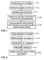
- step S100 a sequence of images is taken, e.g. by a video camera mounted on a vehicle in order to take said sequence of images of a blind spot region, situated near by the vehicle.
- Said images might also be referred to by "frames" or "fields”.
- step S102 the images of said sequence are partitioned into blocks, e.g. into blocks with 8 x 8 pixels each or with 16 x 16 pixels each, but different block sizes or block shapes are also within the scope of the present invention.
- step S104 moving blocks are identified which have moved between consecutive images of said sequence. This might be performed by evaluating the sum of absolute differences of pixel values from a block compared to corresponding blocks of subsequent images in said sequence or by evaluating other known error measures like cross correlation or mean squared errors.
- step S106 a distance and a direction of the movement is determined, e.g. by comparing the position of the moving blocks in consecutive images.
- step S108 adjacent blocks within an image are grouped, for which directions within a predetermined direction interval and distances within a predetermined distance interval have been determined.
- the predetermined direction interval and the predetermined distance interval are used to detect a movement in basically the same direction by basically a same distance.
- the predetermined intervals might be fixed or might be adaptive, e.g. to the actual directions or distances of said moving blocks._This movement might also be determined by calculating a motion vector between blocks of consecutive images and comparing said motion vectors.
- Such grouped adjacent blocks are considered a moving object in said blind spot region of the vehicle.
- grouping also the wordings “segmenting”, “segmentation” or “clustering” might be used within this description.
- At least one false alarm is determined among said moving objects and an alarm is generated only if at least one of said moving objects is no false alarm. Such false alarms might otherwise disturb the driver of a vehicle which no longer would trust the blind spot detection or might result in accidents and injuries.
- an object size of said moving object is determined and compared with a predetermined size.
- a false alarm is generated if said object size is smaller than said predetermined size.
- Small objects are not considered to be a danger for a moving vehicle so that no alarm has to be created, if only such small objects are situated in a blind spot region of the vehicle.
- Small objects below a predetermined size might be no vehicles.
- a vanishing point within said images is determined and said predetermined size depends on a distance of said moving object from said vanishing point.
- the vanishing point within an image normally is used as a point in a perspective drawing to which parallel lines appear to converge. Also in image processing this point can be determined. Objects nearby the vanishing point of an image have a smaller size within the image than objects which appear to be nearer to the vehicle.
- the vanishing point within the images is identified, an object size of the moving object is determined and a vertical distance of the moving object from said vanishing point is determined.
- Objects that are small and high above a vanishing point are normally no danger within a blind spot region of a vehicle, because these objects are not situated on a nearby lane but somewhere in the sky.
- histogram and/or edge-based statistical measures of at least one of said moving objects is calculated, evaluated and a false alarm is generated based on said step of evaluating.
- Such histogram and/or edge-based statistical measures might comprise a variance, an inter quarter range (IQR), a mean, a median, an energy, an edge energy, a uniformity, a smoothness, a third moment and/or an entropy.
- IQR inter quarter range
- Such statistical measures are known from describing images and can be used to classify moving objects. For example, road signs normally show two peaks in a histogram, one at a low luminance value and another one at a high luminance value. Road signs are considered not to be a threat for a vehicle, so that a corresponding false alarm is generated.
- the trajectory of said moving object is evaluated and the false alarm is generated based on said step of evaluating.
- Normally noise occurs for only short time instances and such noise has no trajectory.
- a detection of a moving object might only be considered if the number of trajectory points of the last frames have also been detected as moving objects and the average motion of these frames is positive.
- a size of the moving object is determined and a difference between a region surface and a convex hull of said moving object is calculated, if said size is greater than a predetermined size.
- the moving object is redefined, if said difference is above a predetermined difference. If a region of a moving object is too large and has too many concave parts, it has to be considered further, e.g. it might be_divided into a plurality of moving objects.
- said images of said sequence are split into at least two regions.
- Each region can be treated appropriately with splitting the image into at least two regions. The location where to split depends on a camera mounting angle or the vanishing point, respectively. For instance, when the image is split into two regions this location can be somewhere between the middle and one third of the image width.
- the regions should overlap slightly, to avoid border problems and obtain less abrupt changes between the regions.
- a step S200 the images are split into regions, the blocks are grouped in the regions in a step S202 and false alarm detection is adapted according to the different regions in a step S204.
- the motion estimation and the used algorithms can be adapted better to the different properties within the regions.
- the search range of the motion estimation may be adapted to the region as well as a match block size. For instance, the search range and match block size in the region with the vanishing point is lower than in the region without the vanishing point.
- the training data for a classification is different in all regions, since the perspective is changing. Obstacles in the region with the vanishing point are seen from the front, whereas obstacles in the right area, i.e. the region without the vanishing point are seen from the side.
- the different regions can be cropped or re-sampled to different resolutions, thereby reducing computation time in case of down-scaling, i.e. using less pixels, and allowing sub-pixel accuracy in case of up-scaling, i.e. calculating additional pixel value in-between the measured pixel values.
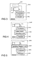
- Fig. 3 an embodiment of blind spot detection device 300 is depicted, which comprises a camera 302, a processor 304 and an indicator 306.
- the camera 302 is configured to take a sequence of images of the blind spot region.
- a monocular camera may be used for the proposed method and system.
- the processor 304 is configured to partition each of said images of said sequence into blocks, to identify moving blocks that have performed a movement between consecutive images of said sequence, to determine a direction and a distance of said movement of said moving blocks, to group adjacent moving blocks, for which directions within a predetermined direction interval and distances within a predetermined distance interval have been determined and to determine said moving objects.
- the indicator 306 is configured to indicate a dangerous situation, if a moving object in said blind spot region has been detected.
- Such indicator might be an alarm sound or an optical signal, e.g. light emitting diode (LED), which is blinking or is emitting light continuously.
- LED light emitting diode
- the blind spot detection device might also comprise active sensors 308 (showed optionally in Fig. 3 ) based on Radar, Lidar, GPS (Global Positioning System) or ultra-sonic to verify the blind spot detection devices with said active sensors.
- active sensors 308 shown optionally in Fig. 3
- Radar Lidar
- GPS Global Positioning System
- ultra-sonic ultra-sonic
- a false alarm detection unit 400 is connected to the processor 304 and to the indicator 306.
- the false alarm detection unit is configured to identify false alarms amongst said moving objects and the indicator 306 is further configured to generate an alarm if at least one of said moving objects is no false alarm.
- a further embodiment of a blind spot detection device which additionally comprises a splitting region unit 500 that is connected to the camera 302 and to the processor 304.
- the splitting region unit 500 is configured to split the images of said sequence into at least two regions.
- a top view of a blind spot region 600 of a vehicle 602, which is driving on a middle lane 603 of a three-lane road is depicted together with a left lane 604 and a right lane 606.
- a left camera 610 is mounted on a left rear view mirror 612 and a right camera 613 is mounted on a right rear view mirror 614.
- the left camera 610 has a left view angle 620 and the right camera 613 has a right view angle 622.
- a first vehicle 630 and a second vehicle 632 behind said first vehicle 630 are driving on the left lane 604.
- On the right lane 606 a third vehicle 634 is approaching the blind spot region 600.
- a "may detect area" 640 is also shown.
- the blind spot region 600 and the may detect area 640 are part of the left view angle 620 and the right view angle 622.
- a vehicle like the first vehicle 630 is inside the blind spot region 600, it is considered as a threat, no matter what velocity it has.
- a vehicle like the third vehicle 634, enters the may detect area 640 it should be detected by the blind spot detection device.
- the third vehicle 634 is considered as a threat if its velocity is too high.
- a vehicle like the second vehicle 632, that is outside the may detect area 640 is not classified as a threat but may also be tracked.
- the blind spot detection device detects vehicles 630, 632, 634 in the blind spot region 600 using a single camera sensor mounted on the own vehicle 602.
- the blind spot 600 on the left side and the right side are handled similar. If a vehicle like the first vehicle 630 is in the blind spot region 600 or other vehicles like the second vehicle 634 are about to enter the blind spot region 600 with high velocity the driver of the own vehicle 602 is warned by an optical sign (e.g. a light emitting diode LED) or by an acoustic signal if the driver intends to change the lanes.
- an optical sign e.g. a light emitting diode LED
- FIG. 7 depicts the processing steps of the proposed approach.
- a camera 610, 612 takes the sequence of images, which are afterwards preprocessed in a step S702, for example by filtering.
- a step S704 a block-based motion estimation is performed which is post-processed in a step S706.
- Blocks which move in the same direction or have the same motion vector are segmented or grouped to moving objects in a step S708.
- step S710 false alarms among the moving objects are detected.
- a box fitting step S712 is performed as an abstract model of the vehicle to which it is fitted to find contact points to a road plane for an angle/distance/velocity estimation that is performed in step S714.
- a threat or danger is identified in step S716 and a corresponding warning is initiated e.g. an acoustic signal is given.
- the angle/ distance /velocity estimation S714 helps to identify objects in a distance which is not dangerous.
- Fig. 8 an image with grouped blocks is depicted. Adjacent blocks with the same motion vector are labeled with the same numbers (1, 2, 3). Different regions are each labeled with individual numbers. It is not known after this grouping or segmenting step, if the region is either a successful detection, as it is the case for the vehicle 802 or a false alarm, as it is the case with the post 840 of a road sign 804 or a crosswalk sign 806.
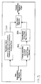
- Fig. 9 a block diagram of the false alarm rejection principle is depicted.
- a plausibility check 900 is performed based on a region size and position, wherein thresholds depend on the distance to the vanishing point.
- a feature extraction 902 based on structural measures or histogram-based features and a corresponding classification 904 are used to detect false alarms that later on are rejected in order to obtain only correct segmented regions as moving objects.
- Local block-based motion estimation is used for the detection of moving objects.
- Detected moving objects are segmented into regions that outline the objects. Every contiguous region that consists of connected blocks is labeled with a different number, wherein a block is connected with the region if the region touches at least one of four (or eight) direct neighboring blocks. Afterwards, a loop through all these regions is used to consider every contiguous region individually. Afterwards a decision is made, which of these regions are false alarms. This decision is based on different plausibility factors.
- Labeled regions with fewer blocks than a certain threshold are rejected.
- the threshold depends on the distance to the vanishing point where cars or vehicles are usually uncovered behind the own obstacle. Since vehicles like cars or vans have a minimum size, detected regions that are small and high above the vanishing points (background/sky) are also rejected. Expensive filtering during post-processing of the vector field can be reduced this way.
- histogram and edge-based statistical texture measures are calculated for these areas. Based on these measures, a decision is made whether to reject the region or to further consider it.
- a classifier is used for the decision.
- Road signs for instance, are usually represented as two high peaks in the histogram, one at higher luminance value and one at a lower luminance value, respectively.
- a Haar transform usually used in face recognition
- IQR inter quartile range
- mean median
- energy edge energy as well as variance or mean in all histograms
- Spectral texture features can be used to detect periodicity and the FFT (Fast Fourier Transformation) does not need not to be computed again by using phase correlation motion estimation.
- the majority of the other false alarms can be suppressed by keeping track of their trajectory. Normally noise occurs only for short time instances and has no trajectory. For instance, a moving object is not considered a false alarm, if a number of the trajectory points of the last frames have also been detected as obstacles and the average motion of this number of frames is positive. At 30 frames per second (fps), e.g. it could be tested, whether two trajectory points of the last three frames are known. A longer history would result in a better decision but a lower response time of the system.
- fps frames per second
- a region is too large and has too many concave parts, it has to be considered further. This can easily be measured as a difference of the region services and of the convex hull surface. The histogram of the motion vectors is taken for this region and the threshold is adapted.
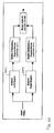
- Fig. 10 a block diagram of the region splitting principle is depicted.
- the images of a sequence are similar.
- Sub-pixel accuracy might be very helpful here, since motion is often between zero and one pixel.
- the sheet metals of closer cars have lower variance since they become larger (per blocks). Otherwise there is more texture near the vanishing point in the left of the image.
- the images are split into at least two regions, e.g. a left region 1202 and a right region 1204, as it is depicted in Fig. 12 . So the image is split into two regions (far and nearby region).
- Fig. 11 a top view of a split camera with slightly overlapping regions 1102 and 1104 is depicted.
- the location where to split depends on the camera mounting angle or the vanishing point 1210 respectively. For instance, this can be somewhere between the middle and one third of the image width.
- the regions might overlap slightly in order to avoid problems at the borders and for less abrupt change.
- the motion estimation and all algorithms can be adapted much better to the different properties of the two regions.
- the search range of the motion estimation may be adapted to the region.
- the search region and the match block size in the right area 1204 are lower than in the left region 1202.
- the training data for the classification is different in the regions because of the changed perspective. Obstacles as moving objects in the left area 1202 is seen from the front, whereas obstacles in the right area 1204 are seen from the side.
- an image 1300 which is split into two regions 1302 and 1304 can be further processed, by up-sampling or down-sampling the number of pixels. Since the structures in the right region 1304 are rather large the down-sampling can be performed in order to reduce computation time. Whereas in the left region 1302 an up-scaling can be performed to allow sub-pixel accuracy. The results of these regions can be later on merged again.
- the monocular passive blind spot detection is based on motion estimation (block-based) where conventional approaches usually have problems.
- false alarms can successfully rejected based on the above-mentioned criteria, and the large search range and motion model related problems can be handled using splitting of regions. So the system performance, accuracy and reliability may be improved. Additionally to the performance improvement the splitting of regions reduces the computation cost (search range).
- the monocular camera just needs one camera, whereas stereo approaches need an expensive second camera and difficult depth estimation.
- the proposed device and method is completely passive, which makes it very cheap and no interference with other active sensors can occur.
- the system can handle monochrome as well as color images.
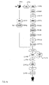
- a camera sensor S1402 takes a sequence of images which are afterwards pre-processed in a step S1404, e.g. a filtering step. Afterwards a block-based motion estimation is performed in step S1406, wherein in a step S1408 the forward/backward motion vector combination is used, to which in a next step S1410 a median filter is applied. Border motion vectors are suppressed in a next step S1412 and a transformation of Cartesian to polar coordinates is performed in the next step S 1414.
- Implausible motion vectors are suppressed in a next step S1416 and afterwards a segmentation or a grouping of blocks with similar motion vectors is performed in a step S1418.
- the objects are closed in a step S1420 and the corresponding regions are labeled in a step S1422.
- a step S1424 a feature extraction is performed on a sequence of images taken by the camera sensor S1402 and the features are classified in the next step S 1426 with the help of training data.
- the result of the classification in step S 1426 and the result of the labeling of regions in step S1422 are combined so that for all labels a false alarm rejection step S 1428 is performed thereby taking into account a region trajectory in a step S1430.
- a box fitting in a step S1430 and a distance calculation in a step S1432 is performed for all labels so that afterwards a flat decision in a step S1434 can be performed.
Landscapes
- Engineering & Computer Science (AREA)
- Physics & Mathematics (AREA)
- General Physics & Mathematics (AREA)
- Multimedia (AREA)
- Theoretical Computer Science (AREA)
- Computer Vision & Pattern Recognition (AREA)
- Image Analysis (AREA)
- Traffic Control Systems (AREA)
- Image Processing (AREA)
- Length Measuring Devices By Optical Means (AREA)
Priority Applications (5)
| Application Number | Priority Date | Filing Date | Title |
|---|---|---|---|
| EP07008959A EP1988488A1 (fr) | 2007-05-03 | 2007-05-03 | Procédé de détection d'objets en mouvement dans un angle mort d'un véhicule et dispositif de détection d'un angle mort |
| EP19188942.7A EP3594853A3 (fr) | 2007-05-03 | 2007-05-03 | Procédé de détection d'objets en mouvement dans un angle mort d'un véhicule et dispositif de détection d'un angle mort |
| CN2008101258443A CN101303735B (zh) | 2007-05-03 | 2008-04-30 | 探测车辆盲点区域内运动物体的方法及盲点探测装置 |
| JP2008120555A JP5297078B2 (ja) | 2007-05-03 | 2008-05-02 | 車両の死角における移動物体を検知するための方法、および死角検知装置 |
| US12/114,239 US8040227B2 (en) | 2007-05-03 | 2008-05-02 | Method for detecting moving objects in a blind spot region of a vehicle and blind spot detection device |
Applications Claiming Priority (1)
| Application Number | Priority Date | Filing Date | Title |
|---|---|---|---|
| EP07008959A EP1988488A1 (fr) | 2007-05-03 | 2007-05-03 | Procédé de détection d'objets en mouvement dans un angle mort d'un véhicule et dispositif de détection d'un angle mort |
Related Child Applications (1)
| Application Number | Title | Priority Date | Filing Date |
|---|---|---|---|
| EP19188942.7A Division EP3594853A3 (fr) | 2007-05-03 | 2007-05-03 | Procédé de détection d'objets en mouvement dans un angle mort d'un véhicule et dispositif de détection d'un angle mort |
Publications (1)
| Publication Number | Publication Date |
|---|---|
| EP1988488A1 true EP1988488A1 (fr) | 2008-11-05 |
Family
ID=38921773
Family Applications (2)
| Application Number | Title | Priority Date | Filing Date |
|---|---|---|---|
| EP07008959A Ceased EP1988488A1 (fr) | 2007-05-03 | 2007-05-03 | Procédé de détection d'objets en mouvement dans un angle mort d'un véhicule et dispositif de détection d'un angle mort |
| EP19188942.7A Withdrawn EP3594853A3 (fr) | 2007-05-03 | 2007-05-03 | Procédé de détection d'objets en mouvement dans un angle mort d'un véhicule et dispositif de détection d'un angle mort |
Family Applications After (1)
| Application Number | Title | Priority Date | Filing Date |
|---|---|---|---|
| EP19188942.7A Withdrawn EP3594853A3 (fr) | 2007-05-03 | 2007-05-03 | Procédé de détection d'objets en mouvement dans un angle mort d'un véhicule et dispositif de détection d'un angle mort |
Country Status (4)
| Country | Link |
|---|---|
| US (1) | US8040227B2 (fr) |
| EP (2) | EP1988488A1 (fr) |
| JP (1) | JP5297078B2 (fr) |
| CN (1) | CN101303735B (fr) |
Cited By (6)
| Publication number | Priority date | Publication date | Assignee | Title |
|---|---|---|---|---|
| CN102194239A (zh) * | 2010-03-16 | 2011-09-21 | 索尼公司 | 用于处理图像数据的方法和系统 |
| WO2011131477A1 (fr) * | 2010-04-23 | 2011-10-27 | Valeo Schalter Und Sensoren Gmbh | Procédé pour avertir un conducteur d'un véhicule de la présence d'objets dans une zone d'angle mort et équipement d'assistance de conduite correspondant |
| CN103337168A (zh) * | 2013-06-04 | 2013-10-02 | 深圳市华宝电子科技有限公司 | 一种车辆数据采集方法、装置及系统 |
| CN111507162A (zh) * | 2019-01-30 | 2020-08-07 | 斯特拉德视觉公司 | 基于车辆间通信的协作的盲点警告方法及装置 |
| CN113807325A (zh) * | 2021-11-17 | 2021-12-17 | 南京三叶虫创新科技有限公司 | 一种基于图像处理的线型识别方法及系统 |
| US11682211B2 (en) | 2019-07-05 | 2023-06-20 | Ava Video Security Limited | Computer-implemented method |
Families Citing this family (35)
| Publication number | Priority date | Publication date | Assignee | Title |
|---|---|---|---|---|
| JP2010215787A (ja) | 2009-03-17 | 2010-09-30 | Fujifilm Corp | 無機蛍光体粒子およびそれを用いた分散型エレクトロルミネッセンス素子 |
| EP2419861A1 (fr) * | 2009-04-14 | 2012-02-22 | Koninklijke Philips Electronics N.V. | Extraction d'images clés pour une analyse de contenu vidéo |
| TW201100280A (en) * | 2009-06-19 | 2011-01-01 | Automotive Res & Testing Ct | Collision warning system for vehicle |
| US8527151B2 (en) * | 2009-12-07 | 2013-09-03 | Ford Global Technologies, Llc | Side impact safety system with blind-spot detection radar data fusion |
| JP2012221331A (ja) * | 2011-04-12 | 2012-11-12 | Hitachi Ltd | 映像監視システム及び人数推定方法 |
| US8791802B2 (en) * | 2011-09-09 | 2014-07-29 | Robert Bosch Gmbh | Driver assistance system for reducing blind-spot-detection false alerts |
| EP2578464B1 (fr) * | 2011-10-06 | 2014-03-19 | Honda Research Institute Europe GmbH | Système d'alerte de type vidéo pour un véhicule |
| CN102509089B (zh) * | 2011-11-29 | 2013-06-19 | 青岛科技大学 | 逐行扫描识别斑马线及测量斑马线距离的方法 |
| US20130181860A1 (en) * | 2012-01-16 | 2013-07-18 | Ford Global Technologies, Llc | Radar based multifunctional safety system |
| JP5486031B2 (ja) * | 2012-03-06 | 2014-05-07 | 本田技研工業株式会社 | 配光制御装置 |
| JP5874831B2 (ja) * | 2012-07-27 | 2016-03-02 | 日産自動車株式会社 | 立体物検出装置 |
| CN104512329B (zh) * | 2013-09-27 | 2017-04-05 | 比亚迪股份有限公司 | 倒车安全辅助方法、装置及汽车 |
| KR102233391B1 (ko) * | 2014-06-16 | 2021-03-29 | 팅크웨어(주) | 전자 장치, 전자 장치의 제어 방법 및 컴퓨터 판독 가능한 기록 매체 |
| KR101692628B1 (ko) * | 2014-12-24 | 2017-01-04 | 한동대학교 산학협력단 | 관심영역을 이용하여 차량의 후방 좌우 옆 차선 영역을 감지하는 방법 및 이를 이용한 차량용 영상 모니터링 시스템 |
| JP6543050B2 (ja) * | 2015-03-06 | 2019-07-10 | 株式会社デンソーテン | 障害物検出装置および障害物検出方法 |
| US10923126B2 (en) * | 2015-03-19 | 2021-02-16 | Samsung Electronics Co., Ltd. | Method and device for detecting voice activity based on image information |
| JP6507862B2 (ja) * | 2015-06-02 | 2019-05-08 | トヨタ自動車株式会社 | 周辺監視装置及び運転支援装置 |
| WO2017024458A1 (fr) * | 2015-08-10 | 2017-02-16 | Bayerische Motoren Werke Aktiengesellschaft | Système, procédé et appareil pour véhicule et support lisible par ordinateur |
| JP6775285B2 (ja) * | 2015-09-24 | 2020-10-28 | アルパイン株式会社 | 後側方車両検知警報装置 |
| US10019805B1 (en) * | 2015-09-29 | 2018-07-10 | Waymo Llc | Detecting vehicle movement through wheel movement |
| US20170151909A1 (en) * | 2015-11-30 | 2017-06-01 | Razmik Karabed | Image processing based dynamically adjusting surveillance system |
| CN105667397B (zh) * | 2015-12-30 | 2018-10-16 | 深圳佑驾创新科技有限公司 | 汽车后视系统及方法 |
| US9996752B2 (en) * | 2016-08-30 | 2018-06-12 | Canon Kabushiki Kaisha | Method, system and apparatus for processing an image |
| CN106251701B (zh) * | 2016-09-14 | 2018-11-06 | 郑州轻工业学院 | 基于旋转变焦多摄像头的车辆后视监测报警系统及方法 |
| DE102016218852A1 (de) * | 2016-09-29 | 2018-03-29 | Conti Temic Microelectronic Gmbh | Detektion von Objekten aus Bildern einer Kamera |
| DE102016123207A1 (de) * | 2016-12-01 | 2018-06-07 | HELLA GmbH & Co. KGaA | Verfahren zur Detektion eines Störeinflusses bei einem Radarsignal |
| KR102313026B1 (ko) * | 2017-04-11 | 2021-10-15 | 현대자동차주식회사 | 차량 및 차량 후진 시 충돌방지 보조 방법 |
| US10839266B2 (en) * | 2018-03-30 | 2020-11-17 | Intel Corporation | Distributed object detection processing |
| US10300851B1 (en) * | 2018-10-04 | 2019-05-28 | StradVision, Inc. | Method for warning vehicle of risk of lane change and alarm device using the same |
| US11037303B2 (en) * | 2019-01-31 | 2021-06-15 | Sony Corporation | Optical flow based detection and tracking of multiple moving objects in successive frames |
| KR102540574B1 (ko) * | 2021-02-26 | 2023-06-08 | 이화여자대학교 산학협력단 | 스트레처블 디스플레이를 사용하여 자동차에서 증강 현실을 제공하는 방법, 이를 수행하기 위한 기록 매체 및 장치 |
| CN113205704B (zh) * | 2021-03-19 | 2022-06-24 | 深圳市点创科技有限公司 | 一种用于大型车辆的盲区检测方法、装置及存储介质 |
| CN114202965B (zh) * | 2022-02-18 | 2022-05-17 | 上海齐感电子信息科技有限公司 | 辅助驾驶方法、装置、车载终端及存储介质 |
| CN115147726B (zh) * | 2022-09-05 | 2023-03-24 | 清华大学 | 城市形态图的生成方法、装置、电子设备和可读存储介质 |
| FR3155191A1 (fr) * | 2023-11-13 | 2025-05-16 | Continental Autonomous Mobility Germany GmbH | Détection de segments |
Citations (2)
| Publication number | Priority date | Publication date | Assignee | Title |
|---|---|---|---|---|
| JP2000285245A (ja) | 1999-03-31 | 2000-10-13 | Toshiba Corp | 移動体の衝突防止装置、衝突防止方法、および記録媒体 |
| EP1562146A2 (fr) | 2004-02-06 | 2005-08-10 | Sharp Kabushiki Kaisha | Détection, à base d'image, de mouvement dans l'environnement d'un véhicule |
Family Cites Families (17)
| Publication number | Priority date | Publication date | Assignee | Title |
|---|---|---|---|---|
| DE4332612C2 (de) | 1992-09-25 | 1996-02-22 | Yazaki Corp | Außenansichts-Überwachungsverfahren für Kraftfahrzeuge |
| US7049945B2 (en) | 2000-05-08 | 2006-05-23 | Automotive Technologies International, Inc. | Vehicular blind spot identification and monitoring system |
| US6488369B1 (en) * | 2000-01-31 | 2002-12-03 | Hewlett-Packard Company | Ink container configured to establish reliable electrical and fluidic connections to a receiving station |
| ES2158827B1 (es) | 2000-02-18 | 2002-03-16 | Fico Mirrors Sa | Dispositivo de deteccion de presencia de objetos. |
| US6678413B1 (en) * | 2000-11-24 | 2004-01-13 | Yiqing Liang | System and method for object identification and behavior characterization using video analysis |
| WO2004021546A2 (fr) | 2002-08-09 | 2004-03-11 | Conti Temic Microelectronic Gmbh | Moyen de transport pourvu d'une camera de prise de vues telemetriques 3d, etprocede pour monter et faire fonctionner cette camera dans des moyens de transport, en particulier dans des vehicules automobiles |
| FR2854692B1 (fr) | 2003-05-07 | 2006-02-17 | Peugeot Citroen Automobiles Sa | Dispositif d'exploration optique et vehicule comportant un tel dispositif |
| JP4628712B2 (ja) * | 2004-07-09 | 2011-02-09 | 財団法人生産技術研究奨励会 | 画像上移動物体認識方法及び装置 |
| JP4039423B2 (ja) * | 2004-12-14 | 2008-01-30 | 日産自動車株式会社 | エッジ位置算出装置、障害物検出システム |
| JP2006197034A (ja) * | 2005-01-11 | 2006-07-27 | Sumitomo Electric Ind Ltd | 画像認識システム、撮像装置及び画像認識方法 |
| JP4277217B2 (ja) * | 2005-02-04 | 2009-06-10 | 住友電気工業株式会社 | 接近移動体表示装置、システム及び方法、並びに衝突情報提供装置及び方法 |
| JP4517393B2 (ja) * | 2005-02-16 | 2010-08-04 | 株式会社デンソー | 運転支援装置 |
| JP4687160B2 (ja) * | 2005-03-14 | 2011-05-25 | アイシン精機株式会社 | 周辺監視装置 |
| JP4539378B2 (ja) * | 2005-03-08 | 2010-09-08 | アイシン・エィ・ダブリュ株式会社 | 運転支援装置及び運転支援方法 |
| JP2006318272A (ja) * | 2005-05-13 | 2006-11-24 | Nissan Motor Co Ltd | 車両用物体検出装置、および方法 |
| US7804980B2 (en) * | 2005-08-24 | 2010-09-28 | Denso Corporation | Environment recognition device |
| US20080166018A1 (en) * | 2007-01-05 | 2008-07-10 | Motorola, Inc. | Method and apparatus for performing object recognition on a target detected using motion information |
-
2007
- 2007-05-03 EP EP07008959A patent/EP1988488A1/fr not_active Ceased
- 2007-05-03 EP EP19188942.7A patent/EP3594853A3/fr not_active Withdrawn
-
2008
- 2008-04-30 CN CN2008101258443A patent/CN101303735B/zh not_active Expired - Fee Related
- 2008-05-02 JP JP2008120555A patent/JP5297078B2/ja not_active Expired - Fee Related
- 2008-05-02 US US12/114,239 patent/US8040227B2/en active Active
Patent Citations (2)
| Publication number | Priority date | Publication date | Assignee | Title |
|---|---|---|---|---|
| JP2000285245A (ja) | 1999-03-31 | 2000-10-13 | Toshiba Corp | 移動体の衝突防止装置、衝突防止方法、および記録媒体 |
| EP1562146A2 (fr) | 2004-02-06 | 2005-08-10 | Sharp Kabushiki Kaisha | Détection, à base d'image, de mouvement dans l'environnement d'un véhicule |
Non-Patent Citations (2)
| Title |
|---|
| "Vehicle detection and tracking using the block matching algorithm", RECENT ADVANCES IN SIGNAL PROCESSING AND COMMUNICATIONS, 1999, pages 160 - 165 |
| DI STEFANO LUIGI ET AL: "Vehicle detection and tracking using the block matching algorithm", RECENT ADVANCES IN SIGNAL PROCESSING AND COMMUNICATIONS - WORLD SCIENTIFIC AND ENGINEERING ACADEMY AND SOCIETY, 1999, pages 160 - 165, XP007903993 * |
Cited By (12)
| Publication number | Priority date | Publication date | Assignee | Title |
|---|---|---|---|---|
| CN102194239A (zh) * | 2010-03-16 | 2011-09-21 | 索尼公司 | 用于处理图像数据的方法和系统 |
| EP2372642A1 (fr) | 2010-03-16 | 2011-10-05 | Sony Corporation | Procédé et système de détection d'objets en mouvement |
| US8406472B2 (en) | 2010-03-16 | 2013-03-26 | Sony Corporation | Method and system for processing image data |
| CN102194239B (zh) * | 2010-03-16 | 2016-04-06 | 索尼公司 | 用于处理图像数据的方法和系统 |
| WO2011131477A1 (fr) * | 2010-04-23 | 2011-10-27 | Valeo Schalter Und Sensoren Gmbh | Procédé pour avertir un conducteur d'un véhicule de la présence d'objets dans une zone d'angle mort et équipement d'assistance de conduite correspondant |
| CN103337168A (zh) * | 2013-06-04 | 2013-10-02 | 深圳市华宝电子科技有限公司 | 一种车辆数据采集方法、装置及系统 |
| CN103337168B (zh) * | 2013-06-04 | 2015-09-02 | 深圳市华宝电子科技有限公司 | 一种车辆数据采集方法、装置及系统 |
| CN111507162A (zh) * | 2019-01-30 | 2020-08-07 | 斯特拉德视觉公司 | 基于车辆间通信的协作的盲点警告方法及装置 |
| CN111507162B (zh) * | 2019-01-30 | 2023-11-07 | 斯特拉德视觉公司 | 基于车辆间通信的协作的盲点警告方法及装置 |
| US11682211B2 (en) | 2019-07-05 | 2023-06-20 | Ava Video Security Limited | Computer-implemented method |
| CN113807325A (zh) * | 2021-11-17 | 2021-12-17 | 南京三叶虫创新科技有限公司 | 一种基于图像处理的线型识别方法及系统 |
| CN113807325B (zh) * | 2021-11-17 | 2022-02-22 | 南京三叶虫创新科技有限公司 | 一种基于图像处理的线型识别方法及系统 |
Also Published As
| Publication number | Publication date |
|---|---|
| EP3594853A3 (fr) | 2020-04-08 |
| CN101303735A (zh) | 2008-11-12 |
| JP2009064410A (ja) | 2009-03-26 |
| EP3594853A2 (fr) | 2020-01-15 |
| US8040227B2 (en) | 2011-10-18 |
| CN101303735B (zh) | 2013-03-20 |
| JP5297078B2 (ja) | 2013-09-25 |
| US20080309516A1 (en) | 2008-12-18 |
Similar Documents
| Publication | Publication Date | Title |
|---|---|---|
| US8040227B2 (en) | Method for detecting moving objects in a blind spot region of a vehicle and blind spot detection device | |
| US10970871B2 (en) | Estimating two-dimensional object bounding box information based on bird's-eye view point cloud | |
| CN111016929B (zh) | 对关于车辆变更车道的危险发出警报的方法及装置 | |
| EP2993654B1 (fr) | Procédé et système d'avertissement de collision | |
| EP3296923B1 (fr) | Procédé de détection d'un véhicule en dépassement, système de traitement associé, système de détection de véhicule en dépassement et véhicule | |
| US7027615B2 (en) | Vision-based highway overhead structure detection system | |
| JP3822515B2 (ja) | 障害物検知装置及びその方法 | |
| EP3007099B1 (fr) | Système de reconnaissance d'image pour véhicule et procédé correspondant | |
| US7545956B2 (en) | Single camera system and method for range and lateral position measurement of a preceding vehicle | |
| EP2833096B1 (fr) | Procédé permettant de déterminer une distance actuelle et/ou une vitesse actuelle d'un objet cible basé sur un point de référence dans une image de caméra, système de caméra et véhicule à moteur | |
| EP2741234B1 (fr) | Localisation de l'objet en utilisant la symétrie verticale | |
| CN107229906A (zh) | 一种基于可变部件模型算法的汽车超车预警方法 | |
| Berriel et al. | A particle filter-based lane marker tracking approach using a cubic spline model | |
| KR101103526B1 (ko) | 스테레오 카메라를 이용한 충돌회피 방법 | |
| Yoneda et al. | Simultaneous state recognition for multiple traffic signals on urban road | |
| Riera et al. | Driver behavior analysis using lane departure detection under challenging conditions | |
| Kim et al. | An intelligent and integrated driver assistance system for increased safety and convenience based on all-around sensing | |
| Hwang et al. | Vision-based vehicle detection and tracking algorithm design | |
| Seo et al. | Use of a monocular camera to analyze a ground vehicle’s lateral movements for reliable autonomous city driving | |
| Saboune et al. | A visual blindspot monitoring system for safe lane changes | |
| JP2011090490A (ja) | 障害物認識装置 | |
| KR20070019347A (ko) | 자동 주행 시스템의 이동체 검출 장치 및 그 방법 | |
| Inoue et al. | Following vehicle detection using multiple cameras | |
| KR102039814B1 (ko) | 측후방 차량 검출 방법 및 그 장치 | |
| JP4381394B2 (ja) | 障害物検知装置及びその方法 |
Legal Events
| Date | Code | Title | Description |
|---|---|---|---|
| PUAI | Public reference made under article 153(3) epc to a published international application that has entered the european phase |
Free format text: ORIGINAL CODE: 0009012 |
|
| AK | Designated contracting states |
Kind code of ref document: A1 Designated state(s): AT BE BG CH CY CZ DE DK EE ES FI FR GB GR HU IE IS IT LI LT LU LV MC MT NL PL PT RO SE SI SK TR |
|
| AX | Request for extension of the european patent |
Extension state: AL BA HR MK RS |
|
| 17P | Request for examination filed |
Effective date: 20090408 |
|
| 17Q | First examination report despatched |
Effective date: 20090514 |
|
| AKX | Designation fees paid |
Designated state(s): DE FR GB |
|
| STAA | Information on the status of an ep patent application or granted ep patent |
Free format text: STATUS: THE APPLICATION HAS BEEN REFUSED |
|
| 18R | Application refused |
Effective date: 20190325 |