EP1988524B1 - Dispositif d'alerte doté d'un déclenchement manuel et affichage d'alarme - Google Patents
Dispositif d'alerte doté d'un déclenchement manuel et affichage d'alarme Download PDFInfo
- Publication number
- EP1988524B1 EP1988524B1 EP20080102693 EP08102693A EP1988524B1 EP 1988524 B1 EP1988524 B1 EP 1988524B1 EP 20080102693 EP20080102693 EP 20080102693 EP 08102693 A EP08102693 A EP 08102693A EP 1988524 B1 EP1988524 B1 EP 1988524B1
- Authority
- EP
- European Patent Office
- Prior art keywords
- sliding plate
- marking
- signalling apparatus
- signalling
- observation device
- Prior art date
- Legal status (The legal status is an assumption and is not a legal conclusion. Google has not performed a legal analysis and makes no representation as to the accuracy of the status listed.)
- Active
Links
Images



Classifications
-
- G—PHYSICS
- G08—SIGNALLING
- G08B—SIGNALLING SYSTEMS, e.g. PERSONAL CALLING SYSTEMS; ORDER TELEGRAPHS; ALARM SYSTEMS
- G08B25/00—Alarm systems in which the location of the alarm condition is signalled to a central station, e.g. fire or police telegraphic systems
- G08B25/12—Manually actuated calamity alarm transmitting arrangements emergency non-personal manually actuated alarm, activators, e.g. details of alarm push buttons mounted on an infrastructure
Definitions
- the invention relates to a signaling device with manual release, in particular a manual call point, with a housing, with a sliding plate which is slidably disposed in the housing between a normal position and a reporting position, and with a mark which is hidden when the sliding plate in the Normal position is visible, and is visible when the sliding plate is in the message position.
- Manual call points are regulated, for example, in the standard EN 54-11, whereby a distinction is made between a type A and a type B.
- type A design an alarm is triggered by destroying or even moving an element.
- type B type manual actuation of a triggering element, for example a push button, is additionally required.
- the alarm shall be indicated to the user by an additional marking so that the display of the marking shall acknowledge the triggering of the manual call point by the user.
- a general state of the art to manual call points forms the published patent application DE 198 353 18 A1 which relates to a manually operated type B detector.
- the detector has a housing with a front view window, behind which an actuating means for triggering a message in the form of a push button is arranged, and additional display means which can give the user different information about the purpose and / or the operating state of the detector.
- WO-0111585 describes the state of the art.
- the invention corresponds to a reporting device according to claim 1.
- a signaling device with manual triggering in particular a manual call point indicator and / or a fire push button detector, is proposed, which is preferably designed in conformity with the standard EN 54-11, in particular with regard to the type A.
- Such signaling devices are used, for example, as components in complex fire detection systems installed in buildings or public places.
- the signaling device has a housing in which a sliding plate is slidably disposed, wherein the sliding plate can change between a normal position and a reporting position.
- the movement type of the sliding movement can be embodied as pure linear displacement, pure rotational or pivotal displacement or superimposition of these movements, in particular in only one plane, or as a complex movement describing a trajectory in three-dimensional space.
- the transition between the normal position to the message position is initiated or effected by the manual triggering, ie the triggering of the message device by a user. If the signaling device is triggered, the sliding plate moves inside the reporting device, for example, such that a micro-switch is switched and thus a message, in particular an alarm is triggered.
- the signaling device has a marking which is concealed, in particular invisible, when the sliding plate is in the normal position and which is visible when the sliding plate is in the signaling position. The user can tell from the visible marking that the message device has been triggered.
- the marking may be formed as a color field, lettering, pictogram or the like, in alternative embodiments, the marking as an active element, such. a warning lamp, a display, etc. realized.
- the sliding plate is arranged displaceable relative to the marking.
- sliding plate and marking are not fixed or rigidly connected. Rather, the manual triggering of the signaling device leads to a relative movement between the sliding plate and marking, with the result that after the relative movement, the mark is visible to the user.
- the sliding plate In the normal position, the sliding plate is preferably positioned in front of the marking in such a way that it is concealed and positioned in the signaling position so that it is visible.
- the sliding plate on a moving observation device through which the mark is visible when the sliding plate is in the reporting position.
- the reporting device is designed so that the observation device overlaps in the observation direction of the user with the marking when the sliding plate is in the reporting position and / or observation device and marking are arranged without overlapping in the observation direction when the sliding plate is arranged in the normal position.
- the observation device can be designed for example as a magnifying glass or another optical element, such as a diffractive optic or as a color or polarizing film.
- the co-moving observer is formed as a co-moving observation window, e.g. is realized as a transparent disc or - in the simplest case - as a free passage opening.
- the manual release, the sliding plate is moved in the housing, whereas the mark is arranged in the housing stationary. This training helps to design the release mechanism constructively simple.
- the sliding plate is formed opaque with the exception of co-moving observation device.
- the sliding plate may be provided, for example, that the sliding plate is provided with a color foil, in particular white foil, or printed with ink, in particular white color.
- the reporting device is designed so that - when the slide plate is in the normal position - a normal color range is visible to the user through the mitbewegte observation device.
- the normal color area is preferably also arranged stationary and, in particular in the immediate vicinity of the marking, optionally positioned on a same carrier.
- the opaque region of the sliding plate and the normal color region have the same color and / or the same surface structuring and / or the same appearance.
- the signaling device in the untripped state, wherein the sliding plate is in the normal position a particularly substantially homogeneous surface, which is formed from the opaque region of the sliding plate and in the region of the observation device of the sliding plate through the normal color range.
- the user perceives the opaque region of the sliding plate and the visible in the area of the observation device marker.
- the reporting device on a control panel, which is designed to trigger the reporting device.
- the housing is closed by the control panel on the operating side, in particular on the front side.
- the control panel may be formed as an insert in a window of the housing of the reporting device.
- this control panel is designed as a fragile element, in particular as a glass, which is triggered by the breaking of the glass, the particular automatic and / or automatic change between the normal position and the reporting position of the sliding plate.
- the operating panel is designed as an unbreakable element in the context of the tripping operation, in particular in such a way that the signaling apparatus can be reset from a tripped condition to an untreated condition without the replacement of components.
- control panel is formed as a plastic disc which is arranged elastically deformable and / or displaceable perpendicular to its surface extension, so that at least partially pressed into the housing of the annunciator by a force application of the user the control panel and there the transition between normal position and reporting position of Sliding plate triggers.
- the invention comprises the embodiment that the control panel is transparent, in particular transparent or translucent.
- the control panel is opaque and has a stationary, in particular stationary on or in the control panel arranged observation device through which the mark is visible when the sliding plate is in the signaling position.
- the control panel with the exception of the stationary observation device is preferably provided with a color foil, in particular a white foil, and / or printed with a color, in particular white color.
- the control panel and / or the sliding plate made of a colored plastic, in which in the area of the observation device, in particular in the field of view of the marking in the triggered state of the reporting device, the coloring is recessed.
- the signaling device is designed such that the marking is visible when the stationary observation device, the moving observation device and the marking in the direction of observation of the user are arranged in alignment and / or congruent and / or overlapping.
- the stationary observation device can be realized with the same embodiments, with which also the co-moving observation device can be realized.
- the signaling device is preferably designed so that in the non-triggered state by the stationary observation device, a portion of the opaque region of the sliding plate visible and in the triggered state by the stationary observation device, the mark is recognizable.
- the stationary observation device is arranged centrally in the control panel.
- the opaque region of the sliding plate - at least the portion that is visible to the user in the normal position of the sliding plate through the stationary observation device - and the control panel have the same color and / or the same surface structuring and / or the same appearance , so that a homogeneous overall image of the control panel is shown with the opaque region of the sliding plate in the unresolved state of the signaling device.
- the stationary and / or mitbewegte observation device is designed as an observation window, which has the form of a hint or warning symbol and / or icon.
- the shape is designed as a standard marking of the operating part and / or the sliding plate, which consists for example of a dot and two arrows. In this embodiment would change in the reporting case, the background behind these symbols and thus display the message.
- the FIG. 1 shows a manual call point 1 in a schematic plan view from the front in a non-triggered state.
- the manual call point detector 1 comprises a housing 2, which shows a nearly square basic shape in plan view, in which a cover plate 3 is arranged on the edge side and in the center a control plate 4.
- the control panel 4 shows in plan view from the front a rectangular basic shape, the height of the control panel 4 is between one third and half the height of the housing 2 and the width of the control panel 4 extends to protruding edge strips over the entire width of the housing 2 ,
- the control panel 4 is formed of a resilient plastic, so that the control panel 4 can be elastically deformed or displaced by a user in a manual release of the manual call point 1.
- the control panel 4 is formed for example of a colored plastic, coated with a white film or printed with white paint, but a stationary, rectangular observation window 5, which in the FIG. 1 is shown in dashed lines, omitted from the color and instead is transparent and / or transparent and / or translucent.
- the FIG. 2 shows the manual call point 1 in the same representation as the FIG. 1 , but now in the triggered state.
- the triggered state of the manual call point detector 1 can be recognized by the user in that a marking 6 is visible in the stationary observation window 5.
- the marker is formed, for example, as a red color field.
- FIG. 3 shows in a schematic three-dimensional representation of a view into the open housing 2, wherein a housing cover and other components of the manual calliper 1 were suppressed drawing.
- the lower housing part 8 is formed, for example, as a one-piece plastic injection molded part and has, in addition to mounting holes 9, which for mounting the Housing bottom are formed on a wall, a plurality of molded elements, the function of which will be explained in connection with the following figures.
- a planar region is arranged, which is formed by the top of a printed circuit board cover 10 behind a printed circuit board (not shown), which ensures the electronic functions of the manual call point 1 is formed.
- the mark 6 is applied, which is thus arranged stationary in the interior of the housing 2.
- the marking 6 is - as well as the observation window 5 - rectangular.
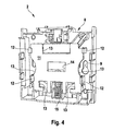
- FIG. 4 shows the lower housing part 8, wherein additionally a slide plate 11 is superimposed, which is arranged in a plane parallel to the rear or front of the manual calliper 1 slidably.
- the sliding plate 11 In the illustrated position, the sliding plate 11 is in a normal position, which characterizes the non-triggered state of the manual call point 1.
- the linear displacement movement is ensured by guide elements 12, which on both sides of the sliding plate 11 hook-like and leader surround.
- the sliding plate 11 is plate-shaped and has at its top, bottom and on the edge sides each open to the edge recesses 13, which are formed on the top and the flank sides, the collision contour of the sliding plate 11 to the lower lid part 8 and the mounting holes 9 adapt and create on the bottom functional elements for holding and releasing the slide plate 11.
- the central region of the sliding plate 11 is formed by a plate-shaped portion in which a co-moving observation window 14 is introduced as a rectangular passage or recess.
- the sliding plate 11 has the same color presentation as the control panel 4, wherein the color presentation is also realized either by coloring the plastic of the sliding plate 11, a glued foil, a coating or a paint job. Attention is still on a spring device 15, which is designed to move the sliding plate 11 by means of spring force after being triggered by the control panel 4.
- FIG. 5 shows the same structure as in FIG. 4 in the same representation, wherein the sliding plate 11 in the FIG. 5 is in the message position, that is, the slide plate 11 was triggered by the control panel 4 and linearly moved up.
- the co-moving observation window 14 is arranged congruently to the marking 6 in plan view of the manual call point 1.
- the marking 6 in the surface extension is larger than the observation window 14, so that - regardless of the user's viewing angle - the marking 6 can always be seen through the observation window 14 in the message position.
- the marker 6 extends over the entire printed circuit board cover 10.
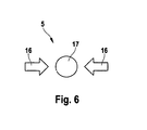
- FIG. 6 finally shows an alternative embodiment for the stationary observation window 5, which is designed as two arrows 16 and a circle 17.
- These pictograms in the arrangement shown correspond to the representations conforming to the standard, so that it is advantageous, at least in the scope of the standard, to use a pictogram or symbol-shaped observation window 5 instead of a rectangular stationary observation window 5.
- the background when the manual call point 1 is triggered, the background changes behind these symbols and thus displays the message.
- the control panel 4 white, the slide plate 11 green and the mark 6 is red, so that upon actuation or a triggering of the manual call point 1, the background of the icon 5 changes from green to red.
Landscapes
- Business, Economics & Management (AREA)
- Emergency Management (AREA)
- Physics & Mathematics (AREA)
- General Physics & Mathematics (AREA)
- Displays For Variable Information Using Movable Means (AREA)
- Fire Alarms (AREA)
- Alarm Systems (AREA)
Claims (12)
- Dispositif d'alerte (1) comprenant un déclenchement manuel, notamment un indicateur d'incendie manuel,
comprenant
un boîtier (2),
une plaque coulissante (11) qui est disposée de manière coulissante dans le boîtier (2) entre une position normale et une position d'alerte,
et un marquage (6) qui est dissimulé quand la plaque coulissante (11) est dans la position normale et qui est visible quand la plaque coulissante (11) est dans la position d'alerte, caractérisé en ce que
la plaque coulissante (11) est disposée de manière déplaçable par rapport au marquage. - Dispositif d'alerte (1) selon la revendication 1, caractérisé en ce que la plaque coulissante (11) présente un dispositif d'observation déplacé en même temps (14), à travers lequel on peut voir le marquage (6), quand la plaque coulissante (11) est dans la position d'alerte.
- Dispositif d'alerte (1) selon l'une quelconque des revendications 1 ou 2, caractérisé en ce que le dispositif d'observation déplacé en même temps est réalisé sous forme de fenêtre d'observation (14) déplacée en même temps.
- Dispositif d'alerte (1) selon l'une quelconque des revendications précédentes, caractérisé en ce que le marquage (6) est disposé de manière stationnaire dans le boîtier (2).
- Dispositif d'alerte (1) selon l'une quelconque des revendications précédentes, caractérisé en ce que la plaque coulissante (11) est réalisé de manière non transparente à l'exception du dispositif d'observation déplacé en même temps (14).
- Dispositif d'alerte (1) selon l'une quelconque des revendications précédentes, caractérisé en ce que lorsque la plaque coulissante (11) se trouve dans la position normale, une région de couleur normale est visible à travers le dispositif d'observation déplacé en même temps (14).
- Dispositif d'alerte (1) selon la revendication 6, caractérisé en ce que la région non transparente de la plaque coulissante (11) et la région de couleur normale présentent la même couleur et/ou la même structuration de surface.
- Dispositif d'alerte (1) selon l'une quelconque des revendications précédentes, caractérisé par une plaque de commande (4) qui est réalisée pour déclencher le dispositif d'alerte (1).
- Dispositif d'alerte (1) selon la revendication 8, caractérisé en ce que la plaque de commande (4) présente un dispositif d'observation stationnaire (5) à travers lequel le marquage est visible quand la plaque coulissante (11) est disposée dans la position d'alerte.
- Dispositif d'alerte (1) selon la revendication 9, caractérisé en ce que l'on peut voir à travers le dispositif d'observation stationnaire (5) une portion de la région non transparente de la plaque coulissante (11), quand la plaque coulissante (11) est disposée dans la position normale.
- Dispositif d'alerte (1) selon la revendication 9 ou 10, caractérisé en ce que la région non transparente de la plaque coulissante (11) et la plaque de commande (4) présentent la même couleur et/ou la même structuration de surface.
- Dispositif d'alerte (1) selon l'une quelconque des revendications 9 à 11, caractérisé en ce que le dispositif d'observation stationnaire (5) est réalisé sous la forme d'une fenêtre d'observation stationnaire qui présente la forme d'un symbole et/ou d'un pictogramme d'indication ou d'avertissement (16, 17).
Applications Claiming Priority (1)
| Application Number | Priority Date | Filing Date | Title |
|---|---|---|---|
| DE200710020284 DE102007020284A1 (de) | 2007-04-30 | 2007-04-30 | Meldevorrichtung mit manueller Auslösung und Alarmanzeige |
Publications (3)
| Publication Number | Publication Date |
|---|---|
| EP1988524A2 EP1988524A2 (fr) | 2008-11-05 |
| EP1988524A3 EP1988524A3 (fr) | 2009-09-09 |
| EP1988524B1 true EP1988524B1 (fr) | 2010-10-27 |
Family
ID=39645510
Family Applications (1)
| Application Number | Title | Priority Date | Filing Date |
|---|---|---|---|
| EP20080102693 Active EP1988524B1 (fr) | 2007-04-30 | 2008-03-18 | Dispositif d'alerte doté d'un déclenchement manuel et affichage d'alarme |
Country Status (4)
| Country | Link |
|---|---|
| EP (1) | EP1988524B1 (fr) |
| CN (1) | CN101299291B (fr) |
| DE (2) | DE102007020284A1 (fr) |
| ES (1) | ES2354643T3 (fr) |
Families Citing this family (1)
| Publication number | Priority date | Publication date | Assignee | Title |
|---|---|---|---|---|
| CN102208126B (zh) * | 2010-03-31 | 2013-06-12 | 西门子公司 | 手动报警装置 |
Family Cites Families (4)
| Publication number | Priority date | Publication date | Assignee | Title |
|---|---|---|---|---|
| CN2251168Y (zh) * | 1996-04-01 | 1997-04-02 | 朱劲虹 | 手动声光报警按钮盒 |
| DE19835318B4 (de) | 1998-02-02 | 2007-07-26 | Robert Bosch Gmbh | Manuell betätigbare Melder |
| DE60030864T2 (de) * | 1999-08-10 | 2007-04-19 | Fulleon Ltd., Cwmbran | Notrufschalter oder zerbrechbare glaseinheiten |
| GB2401992B (en) * | 2003-05-17 | 2006-12-13 | Kac Alarm Company Ltd | Call points |
-
2007
- 2007-04-30 DE DE200710020284 patent/DE102007020284A1/de not_active Withdrawn
-
2008
- 2008-03-18 EP EP20080102693 patent/EP1988524B1/fr active Active
- 2008-03-18 DE DE200850001620 patent/DE502008001620D1/de active Active
- 2008-03-18 ES ES08102693T patent/ES2354643T3/es active Active
- 2008-04-30 CN CN 200810096000 patent/CN101299291B/zh not_active Expired - Fee Related
Also Published As
| Publication number | Publication date |
|---|---|
| EP1988524A2 (fr) | 2008-11-05 |
| DE102007020284A1 (de) | 2008-11-06 |
| EP1988524A3 (fr) | 2009-09-09 |
| CN101299291B (zh) | 2013-04-10 |
| DE502008001620D1 (de) | 2010-12-09 |
| ES2354643T3 (es) | 2011-03-16 |
| CN101299291A (zh) | 2008-11-05 |
Similar Documents
| Publication | Publication Date | Title |
|---|---|---|
| DE4205289A1 (de) | Zustandsanzeige fuer schalterkontakte | |
| DE102014218493A1 (de) | Anzeige- und Bedienvorrichtung, insbesondere für ein Kraftfahrzeug, Bedienelement und Kraftfahrzeug | |
| EP2206132B1 (fr) | Actionneur | |
| DE102011008989A1 (de) | Schaltervorrichtung | |
| EP0011323A1 (fr) | Bouton-poussoir pour commutateur | |
| EP1988524B1 (fr) | Dispositif d'alerte doté d'un déclenchement manuel et affichage d'alarme | |
| EP1965399B1 (fr) | Commutateur d'urgence pour un système d'alerte de danger | |
| EP1632921A2 (fr) | Avertisseur de danger manuel | |
| EP1845505A1 (fr) | Dispositif de bouton-poussoir inscriptible, en particulier bouton de sonnette | |
| DE20109237U1 (de) | Schild | |
| EP2048677A9 (fr) | Dispositif d'utilisation destiné à l'utilisation d'une machine-outil, machine de production et/ou robot | |
| DE6930690U (de) | Installationsschalter mit grossflaechiger betaetigungswippe | |
| DE2455031C2 (de) | Sicherheitsschalter | |
| EP0018483B1 (fr) | Dispositif d'affichage numérique à commande électromécanique | |
| EP1988525A2 (fr) | Dispositif d'alerte doté d'un mécanisme de test et clé spéciale destinée à l'actionnement du mécanisme de test | |
| DE102010037880A1 (de) | Rahmenprofileinsatz, damit ausgestattete Flügelanlage und Montageverfahren dafür | |
| DE102007020283A1 (de) | Meldevorrichtung mit manueller Auslösung | |
| DE2356689C3 (de) | Drucktastenschalter mit einer Anzeigeeinrichtung | |
| DE3246922C2 (fr) | ||
| DE652744C (de) | Malschloss fuer elektrische Stromkreise | |
| DE2113766A1 (de) | Signalgeber fuer den Strassenverkehr | |
| DE3005457A1 (de) | Schalterbetaetigungsorgan mit mechanischer anzeigevorrichtung fuer den schaltzustand eines schalters | |
| DE2220812C3 (de) | Anzeigetastknopf | |
| DE2402484C3 (de) | Mechanische Digital-Anzeigevorrichtung | |
| DE102020110529A1 (de) | Elektrizitätszähler mit einem Schild |
Legal Events
| Date | Code | Title | Description |
|---|---|---|---|
| PUAI | Public reference made under article 153(3) epc to a published international application that has entered the european phase |
Free format text: ORIGINAL CODE: 0009012 |
|
| AK | Designated contracting states |
Kind code of ref document: A2 Designated state(s): AT BE BG CH CY CZ DE DK EE ES FI FR GB GR HR HU IE IS IT LI LT LU LV MC MT NL NO PL PT RO SE SI SK TR |
|
| AX | Request for extension of the european patent |
Extension state: AL BA MK RS |
|
| PUAL | Search report despatched |
Free format text: ORIGINAL CODE: 0009013 |
|
| AK | Designated contracting states |
Kind code of ref document: A3 Designated state(s): AT BE BG CH CY CZ DE DK EE ES FI FR GB GR HR HU IE IS IT LI LT LU LV MC MT NL NO PL PT RO SE SI SK TR |
|
| AX | Request for extension of the european patent |
Extension state: AL BA MK RS |
|
| 17P | Request for examination filed |
Effective date: 20100309 |
|
| AKX | Designation fees paid |
Designated state(s): DE ES GB IT |
|
| GRAP | Despatch of communication of intention to grant a patent |
Free format text: ORIGINAL CODE: EPIDOSNIGR1 |
|
| GRAS | Grant fee paid |
Free format text: ORIGINAL CODE: EPIDOSNIGR3 |
|
| GRAA | (expected) grant |
Free format text: ORIGINAL CODE: 0009210 |
|
| AK | Designated contracting states |
Kind code of ref document: B1 Designated state(s): DE ES GB IT |
|
| REG | Reference to a national code |
Ref country code: GB Ref legal event code: FG4D Free format text: NOT ENGLISH |
|
| REF | Corresponds to: |
Ref document number: 502008001620 Country of ref document: DE Date of ref document: 20101209 Kind code of ref document: P |
|
| REG | Reference to a national code |
Ref country code: ES Ref legal event code: FG2A Effective date: 20110304 |
|
| PLBE | No opposition filed within time limit |
Free format text: ORIGINAL CODE: 0009261 |
|
| STAA | Information on the status of an ep patent application or granted ep patent |
Free format text: STATUS: NO OPPOSITION FILED WITHIN TIME LIMIT |
|
| 26N | No opposition filed |
Effective date: 20110728 |
|
| REG | Reference to a national code |
Ref country code: DE Ref legal event code: R097 Ref document number: 502008001620 Country of ref document: DE Effective date: 20110728 |
|
| PGFP | Annual fee paid to national office [announced via postgrant information from national office to epo] |
Ref country code: IT Payment date: 20210331 Year of fee payment: 14 |
|
| PG25 | Lapsed in a contracting state [announced via postgrant information from national office to epo] |
Ref country code: IT Free format text: LAPSE BECAUSE OF NON-PAYMENT OF DUE FEES Effective date: 20220318 |
|
| PGFP | Annual fee paid to national office [announced via postgrant information from national office to epo] |
Ref country code: DE Payment date: 20250522 Year of fee payment: 18 |
|
| PGFP | Annual fee paid to national office [announced via postgrant information from national office to epo] |
Ref country code: ES Payment date: 20250416 Year of fee payment: 18 |
|
| PGFP | Annual fee paid to national office [announced via postgrant information from national office to epo] |
Ref country code: GB Payment date: 20260324 Year of fee payment: 19 |