EP1988525A2 - Dispositif d'alerte doté d'un mécanisme de test et clé spéciale destinée à l'actionnement du mécanisme de test - Google Patents
Dispositif d'alerte doté d'un mécanisme de test et clé spéciale destinée à l'actionnement du mécanisme de test Download PDFInfo
- Publication number
- EP1988525A2 EP1988525A2 EP08102694A EP08102694A EP1988525A2 EP 1988525 A2 EP1988525 A2 EP 1988525A2 EP 08102694 A EP08102694 A EP 08102694A EP 08102694 A EP08102694 A EP 08102694A EP 1988525 A2 EP1988525 A2 EP 1988525A2
- Authority
- EP
- European Patent Office
- Prior art keywords
- special key
- signaling device
- test mechanism
- test
- support block
- Prior art date
- Legal status (The legal status is an assumption and is not a legal conclusion. Google has not performed a legal analysis and makes no representation as to the accuracy of the status listed.)
- Granted
Links
Images


Classifications
-
- G—PHYSICS
- G08—SIGNALLING
- G08B—SIGNALLING SYSTEMS, e.g. PERSONAL CALLING SYSTEMS; ORDER TELEGRAPHS; ALARM SYSTEMS
- G08B25/00—Alarm systems in which the location of the alarm condition is signalled to a central station, e.g. fire or police telegraphic systems
- G08B25/12—Manually actuated calamity alarm transmitting arrangements emergency non-personal manually actuated alarm, activators, e.g. details of alarm push buttons mounted on an infrastructure
Definitions
- the invention relates to a message device with manual release, in particular a manual call point, with a housing and with a fragile element which closes the housing operator side to the user and which must be broken for manual activation of the reporting device by the user.
- Manual call points are components of often complex fire detection systems and allow a user to trigger a fire alarm by manual operation.
- the manual call points are regulated, for example, in the standard EN 54-11, whereby a distinction is made between a type A and a type B.
- type A design an alarm is triggered by destroying or even moving an element.
- type B type the manual operation of a trigger element, for example a push button, is additionally required.
- a general state of the art to manual fire alarms forms the published patent application DE 198 35 318 A1 which relates to a manually operated type B detector.
- the detector has a housing with a front view window, behind which an actuating means for triggering a message in the form of a push button is arranged, and additional display means which can give the user different information about the purpose and / or the operating state of the detector.
- a manual release alarm device in particular a manual call point indicator and / or a fire push button detector, which is preferably designed in conformity with the standard EN 54-11, in particular with regard to the types A and B with a frangible element.
- signaling devices are used, for example, as components in complex fire detection systems installed in buildings or public places.
- the signaling device has a housing which is designed, for example, as a housing lower part with a pivotable door or a housing lower part with a removable cover.
- the housing is user-terminated with a fragile element.
- the fragile element is preferably plate-shaped or formed as a plate and in particular made of glass or plastic. In the case of a plastic disc, this preferably has predetermined breaking points, so that these decays into predetermined portions upon manual activation by the user.
- the signaling device is designed such that upon manual triggering of the signaling device by the user, the fragile element is intentionally broken.
- the reporting device has a test mechanism for a nondestructive functional test, in which in particular the fragile element is not destroyed.
- the test mechanism is embodied and / or arranged in such a way that the functional test comprises a displacement of the fragile element, whereby the signaling device is activated or triggered by the displacement.
- the functional test and the resetting of the signaling device without an exchange of components is possible.
- the invention proposes a test mechanism, which moves the fragile element during the functional test, but without destroying the fragile element, in order to simulate in this way, especially with the housing closed actuation application.
- the present invention describes an advantageous message device with a frangible element, which can be tested in a simple manner, but nevertheless offers a high degree of security against intentional or unwanted false tripping.
- the test mechanism is designed such that during the functional test the displacement of the frangible element takes place along a plane that is parallel or identical to the surface extension of the frangible element.
- the direction of displacement of the fragile element is preferably formed perpendicular to the usual operating direction of the signaling device.
- the signaling device preferably has a switching element which emits a message when actuated, wherein the switching element is actuated directly or indirectly by the frangible element.
- the switching element is thus triggered directly by the fragile element, for example by the switching element and the fragile element having a common contact surface.
- the movement of the frangible element is transmitted via at least one intermediate member to the switching element in order to switch or actuate this.
- this intermediate member is formed as a sliding plate, which preferably operates the switching element directly.
- the sliding plate is slidably disposed in the housing between a normal position - in an unresolved state of the signaling device - and a reporting position - in a triggered state of the signaling device. In the Normal position, the sliding plate is positively held by the fragile element, wherein it is preferably provided that the sliding plate is biased by a weight force or a spring force. Sliding plate and fragile element are coupled in such a way that the sliding plate can be transferred to the reporting position and / or transferred by the displacement of the fragile element.
- the test mechanism comprises a support block, on which rests the fragile element and controls the displacement, wherein the fragile element preferably rests with a free side edge, in particular linearly on the support block.
- the support block is movable, in particular displaceable and / or rotatable.
- the support block has a normal support surface and a test support surface. If the fragile element lies on the normal support surface, then the optionally existing sliding plate is in the normal position. On the other hand, if the fragile element lies on the test support surface, then the fragile element is already displaced, so that the optionally present sliding plate is arranged in the reporting position. It is particularly preferred if the change of the support surface from the normal support surface to the test support surface can be implemented or implemented by a rotation of the support block, in particular about a rotation axis perpendicular to the surface extension of the fragile element.
- the support block has a rectangular shape in cross-section or is formed as a rounded rectangle, wherein the normal support surface are arranged on a narrow side and the test support surface on a longitudinal side.
- This structurally simple embodiment of the invention has the advantage that the fragile element is always kept horizontal in the normal state and in the test state by defined bearing surfaces and / or rests linear.
- the particular embodiment of the support block has the advantage that a certain force must be applied to the operation. This is due to the fact that the fragile element is initially deflected against the actual displacement direction, since due to the rotation of the support block, the fragile element is guided over the diagonal or the corner region of the support block.
- the support block must be rotated and moved for testing, with accidentally triggered by the combined sliding / rotary motion is almost impossible.
- test mechanism it is preferred that it has a mechanical interface which can be actuated exclusively by a special key section, whereas an actuation by standard tools is blocked or prevented.
- This mechanical interface can be designed, for example, as an oval opening with a central retaining mandrel, so that the test mechanism can only be triggered by the special key section adapted to it, but triggering by, for example, a screwdriver etc. is not possible.
- the mechanical interface is secured by a cap, wherein the cap and / or the reporting device has a closure or together form the intended purpose only with a another special key section is open.
- the cap can be either completely removable or hinged to the housing of the reporting device, so that it can be swung away.
- the closure comprises in particular two receiving openings in the housing, in which two nose-shaped extensions of the further special key section can engage in order to pry off the covering cap.
- Another object of the invention relates to a special key, which has the special key portion and the other special key portion, wherein the portions are designed to serve the interface of the test mechanism or the closure of the cap as intended.
- the signaling device is convertible, wherein the sliding plate has projections which are designed to interact positively with a resettable element, which is used instead of the frangible element, so that an actuation of the resettable element to a displacement of the sliding plate from the normal position into a Message position leads.
- the Special key on a third special key section which is designed as a push rod. Message device and special key are adapted to each other that the third special key portion is inserted through a housing opening in the particular closed housing and causes a displacement of the sliding plate against the displacement direction.
- Another object of the invention relates to a method for non-destructive testing of the function of the reporting device according to the features of independent claim 16.
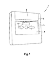
- the FIG. 1 shows in a schematic three-dimensional view obliquely from the front of a manual call point 1, which may for example be part of a complex fire alarm system.
- the manual call point detector 1 comprises a housing 2, which in plan view shows a square or rectangular basic shape and in the edge side a cover cap 3 and in the middle a glass plate 4 is arranged.
- the glass plate 4 covers from the inside of the housing 2 from a front window 5 of the housing, which has a rectangular basic shape, wherein the height of the window 5 between one third and half the height of the housing 2 makes up and the width of the window 5 to projecting edge strip extends over the entire width of the housing 2.
- the glass pane 4 To trigger the manual call point 1, the glass pane 4 must be broken by application of force, already breaking the glass plate 4 is sufficient to trigger the manual call point 1.
- areas 6 e.g. are formed as windows and / or normeetice symbols or pictograms, the background color, as will be explained in detail later.
- the manual fire detector 1 is in the untreated state with a arranged behind the glass 4 homogeneous background and in the tripped state by color highlighted areas 6.
- by striking the glass 4 a arranged inside the housing 2 switching element (not shown) triggered, which sends an electrical signal.
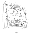
- FIG. 2 shows a schematic three-dimensional view into the housing 2 of the manual call point 1, wherein a lower housing part 7, which is for example formed as an integrally molded injection molded part, can be seen with a plurality of functional components used.
- the glass 4 which has a rectangular basic shape and is held laterally via fastening clips 8.
- the manual call point detector 1 also has a sliding plate 9, which is arranged parallel to the glass plate 4 in the interior of the housing.
- the sliding plate 9 is slidably mounted between a normal position and a reporting position along the direction of arrow 10.
- the normal position corresponds to the unreleased state of the manual call point detector 1, whereas the message position corresponds to the tripped state.
- a spring device 11 which biases the slide plate 9 in the direction 10.
- the sliding plate 9 In the normal position, the sliding plate 9 is, however, with a strip-like extension 12 on a side edge, in FIG. 2 on the lower edge of the glass pane 4, so that the sliding movement is positively locked.
- the glass plate 4 On the opposite side edge of the glass sheet 4, in FIG. 2 the upper edge, the glass plate 4 with the narrow side 13 of a support block 14 in Appendix.
- the sliding plate 9 is supported in the displacement direction 10 via the strip-like shoulder 12 at the lower edge of the glass plate 4, wherein the glass plate 4 is supported in the same direction with the upper edge on the narrow side 13 of the support block 14.
- the manual call point 1 can be dismantled or opened and the switching element, not shown, manually triggered. After this procedure, however, is not completely ruled out that the manual call point 1 is inoperative during subsequent assembly, the points in the FIGS. 1 and 2 shown hand fire detector 1 a test mechanism that allows a test of the manual call point 1 without opening the housing 2 and without destroying the glass plate 4.
- the test mechanism is realized in that the support block 14 is mounted rotatably and optionally displaceable and can be operated with the housing 2 closed.
- FIG. 3 shows the manual fire detector 1 in a test-release, wherein the glass plate 4, in contrast to the preceding figures diagrammatically transparent is shown.
- the support block 14 is rotated about a centrally disposed axis of rotation perpendicular to the surface extension of the glass plate 4, so that the glass plate 4 rests in the final state on a longitudinal side 15 of the support block 14.
- a displacement against the displacement direction 10 to solve a lock is necessary to unlock the support block 14, so that a deliberate false triggering of the manual call point 1 is made difficult by unauthorized persons.
- Due to the bias of the sliding plate 9, the glass plate 4 is offset in the sliding direction 10 together with the sliding plate 9, wherein the sliding plate 9, the switching element, not shown, is triggered.
- the glass plate 4 is supported in each case by the support block parallel to the overlying edge , in addition, it is necessary in the transition from the normal state to the test state of the support block 14 that an actuation resistance due to the corner regions of the support block 14 must be overcome, since first the glass 4 and the slide plate 9 must be moved against the direction of displacement 10.
- the support block 14 from outside the housing 2 is actuated.
- the support block 14 has a mechanical interface 16, which is formed as an oval or elliptical recess with a central mandrel in the support block 14 and via a slot-like or oval opening 17 which is arranged in the housing 2 behind the cover plate 3 is reachable. Due to the special design of the mechanical interface 16 ensures that a test-release can only be achieved by a special tool, which has a matched to the mechanical interface 16 functional section, and not, for example, with a commercially available screwdriver. This measure complicates a deliberate false triggering of the manual call point 1 by unauthorized persons.
- the shutter has two receiving openings 18, which are arranged on the upper edge of the window 5 and the beginning of Form guide channels.
- the guide channels extend in the course initially protected within the housing 2 and are open in an area below the cap 3 to the outside.
- the guide channels allow the insertion of angled, nose-like domes of a special tool, wherein the end portions of the nose-like dome extend to the outwardly open areas.
- Such a special tool 19 is shown, which engages with the angled, nose-like, parallel to each other arranged domes 20 in the receiving openings 18, so that by means of a lifting movement, the cap 3 can be levered.
- the special tool 19 has at one end the dome 20 as functional elements for levering the cap 3. At another end, a special key 21 for actuating the support block 14 is formed with a correspondingly adapted, oval cross section with a central recess. At a third end, the special tool 19 on a push rod 22, which is adapted to move the slide plate 9 from the reporting position to the normal position, as shown in the FIG. 3 is shown.
Landscapes
- Business, Economics & Management (AREA)
- Emergency Management (AREA)
- Physics & Mathematics (AREA)
- General Physics & Mathematics (AREA)
- Fire Alarms (AREA)
- Alarm Systems (AREA)
- Burglar Alarm Systems (AREA)
Applications Claiming Priority (1)
| Application Number | Priority Date | Filing Date | Title |
|---|---|---|---|
| DE200710020282 DE102007020282A1 (de) | 2007-04-30 | 2007-04-30 | Meldevorrichtung mit Testmechanismus sowie Spezialschlüssel zur Betätigung des Testmechanismus |
Publications (3)
| Publication Number | Publication Date |
|---|---|
| EP1988525A2 true EP1988525A2 (fr) | 2008-11-05 |
| EP1988525A3 EP1988525A3 (fr) | 2010-01-06 |
| EP1988525B1 EP1988525B1 (fr) | 2015-09-23 |
Family
ID=39645509
Family Applications (1)
| Application Number | Title | Priority Date | Filing Date |
|---|---|---|---|
| EP08102694.0A Active EP1988525B1 (fr) | 2007-04-30 | 2008-03-18 | Dispositif d'alerte doté d'un mécanisme de test et clé spéciale destinée à l'actionnement du mécanisme de test |
Country Status (4)
| Country | Link |
|---|---|
| EP (1) | EP1988525B1 (fr) |
| CN (1) | CN101299290B (fr) |
| DE (1) | DE102007020282A1 (fr) |
| ES (1) | ES2550360T3 (fr) |
Cited By (1)
| Publication number | Priority date | Publication date | Assignee | Title |
|---|---|---|---|---|
| US10249175B2 (en) | 2015-09-18 | 2019-04-02 | Gulf Security Technology Company Limited | Push plate of manual alarm device |
Families Citing this family (1)
| Publication number | Priority date | Publication date | Assignee | Title |
|---|---|---|---|---|
| EP4428840A1 (fr) * | 2023-03-07 | 2024-09-11 | Tyco Fire & Security GmbH | Point d'appel d'alarme |
Citations (3)
| Publication number | Priority date | Publication date | Assignee | Title |
|---|---|---|---|---|
| EP1503390A2 (fr) | 2003-07-30 | 2005-02-02 | CQR Security Components Limited | Interrupteur d'alarme |
| EP1288881B1 (fr) | 2001-09-03 | 2005-05-18 | Siemens Building Technologies AG | Avertisseur manuel de risques |
| EP1632921B1 (fr) | 2004-09-02 | 2009-11-11 | Novar GmbH | Avertisseur de danger manuel |
Family Cites Families (2)
| Publication number | Priority date | Publication date | Assignee | Title |
|---|---|---|---|---|
| DE19835318B4 (de) | 1998-02-02 | 2007-07-26 | Robert Bosch Gmbh | Manuell betätigbare Melder |
| GB2401992B (en) * | 2003-05-17 | 2006-12-13 | Kac Alarm Company Ltd | Call points |
-
2007
- 2007-04-30 DE DE200710020282 patent/DE102007020282A1/de not_active Withdrawn
-
2008
- 2008-03-18 ES ES08102694.0T patent/ES2550360T3/es active Active
- 2008-03-18 EP EP08102694.0A patent/EP1988525B1/fr active Active
- 2008-04-30 CN CN200810095999.7A patent/CN101299290B/zh active Active
Patent Citations (3)
| Publication number | Priority date | Publication date | Assignee | Title |
|---|---|---|---|---|
| EP1288881B1 (fr) | 2001-09-03 | 2005-05-18 | Siemens Building Technologies AG | Avertisseur manuel de risques |
| EP1503390A2 (fr) | 2003-07-30 | 2005-02-02 | CQR Security Components Limited | Interrupteur d'alarme |
| EP1632921B1 (fr) | 2004-09-02 | 2009-11-11 | Novar GmbH | Avertisseur de danger manuel |
Cited By (1)
| Publication number | Priority date | Publication date | Assignee | Title |
|---|---|---|---|---|
| US10249175B2 (en) | 2015-09-18 | 2019-04-02 | Gulf Security Technology Company Limited | Push plate of manual alarm device |
Also Published As
| Publication number | Publication date |
|---|---|
| ES2550360T3 (es) | 2015-11-06 |
| EP1988525B1 (fr) | 2015-09-23 |
| CN101299290A (zh) | 2008-11-05 |
| DE102007020282A1 (de) | 2008-11-06 |
| EP1988525A3 (fr) | 2010-01-06 |
| CN101299290B (zh) | 2016-01-06 |
Similar Documents
| Publication | Publication Date | Title |
|---|---|---|
| EP0744002B1 (fr) | Systeme de verrouillage declencheur d'alarme pour la zone de fermeture et/ou de charniere d'une porte ou d'une fenetre a acces protege | |
| DE3101791C2 (fr) | ||
| EP2058460B9 (fr) | Dispositif de verrouillage anti-effraction pour batiment | |
| DE19633628A1 (de) | Verfahren und Vorrichtung zum Scharfschalten einer Einbruch-Meldeanlage | |
| EP1988525B1 (fr) | Dispositif d'alerte doté d'un mécanisme de test et clé spéciale destinée à l'actionnement du mécanisme de test | |
| DE19603679C5 (de) | Alarmauslösende Schließeinrichtung für Fenster oder Türen | |
| EP0779945B1 (fr) | Dispositif de fermeture declenchant une alarme pour la zone de fermeture et/ou charniere d'une porte ou d'une fenetre a rendre sure | |
| DE20208183U1 (de) | Vorrichtung zur Sicherung von Notausgangstüren | |
| DE102006046839B4 (de) | Branddruckknopfmelder | |
| DE2814548A1 (de) | Sicherheitsverriegelungsvorrichtung | |
| DE19714594C2 (de) | Alarmauslösendes Schließblech für den Schließbereich einer zu sicherenden Tür oder eines zu sichernden Fensters | |
| AT509234B1 (de) | Überwachungsanordnung für den öffnungszustand eines fensters oder einer tür | |
| DE10006946C2 (de) | Alarmauslösendes Schließblech | |
| DE1919347A1 (de) | Automatische Verriegelung | |
| EP1988524B1 (fr) | Dispositif d'alerte doté d'un déclenchement manuel et affichage d'alarme | |
| EP1618581B1 (fr) | Element d'arret pour appareil electrique | |
| DE19826141B4 (de) | Zuhaltevorrichtung mit Einbruchssicherung | |
| DE19505856A1 (de) | Alarmauslösende Zuhaltevorrichtung für den Schließ- und/oder Scharnierbereich einer zu sichernden Tür oder eines zu sichernden Fensters | |
| EP1988526B1 (fr) | Dispositif de signalisation à déclenchement manuel | |
| EP3140821A1 (fr) | Dispositif de déclenchement d'alarme et de protection anti-effraction pour une fenêtre ou une porte | |
| CH703642B1 (de) | Anordnung zur Überwachung von Verschlusselementen. | |
| DE3227876A1 (de) | Alarmanlage zur sicherung eines durchgangs | |
| DE8118472U1 (de) | Sicherheitsblockschloss fuer eine alarmanlage oder dergleichen | |
| DE19647854A1 (de) | Profilzylinder mit mindestens zwei Schließnasen | |
| DE202004004598U1 (de) | Vorrichtung zur Sicherung bzw. Überwachung von Betätigungsstangen an Paniktüren o.dgl. |
Legal Events
| Date | Code | Title | Description |
|---|---|---|---|
| PUAI | Public reference made under article 153(3) epc to a published international application that has entered the european phase |
Free format text: ORIGINAL CODE: 0009012 |
|
| AK | Designated contracting states |
Kind code of ref document: A2 Designated state(s): AT BE BG CH CY CZ DE DK EE ES FI FR GB GR HR HU IE IS IT LI LT LU LV MC MT NL NO PL PT RO SE SI SK TR |
|
| AX | Request for extension of the european patent |
Extension state: AL BA MK RS |
|
| PUAL | Search report despatched |
Free format text: ORIGINAL CODE: 0009013 |
|
| AK | Designated contracting states |
Kind code of ref document: A3 Designated state(s): AT BE BG CH CY CZ DE DK EE ES FI FR GB GR HR HU IE IS IT LI LT LU LV MC MT NL NO PL PT RO SE SI SK TR |
|
| AX | Request for extension of the european patent |
Extension state: AL BA MK RS |
|
| 17P | Request for examination filed |
Effective date: 20100706 |
|
| AKX | Designation fees paid |
Designated state(s): DE ES GB IT |
|
| 17Q | First examination report despatched |
Effective date: 20100826 |
|
| GRAP | Despatch of communication of intention to grant a patent |
Free format text: ORIGINAL CODE: EPIDOSNIGR1 |
|
| GRAJ | Information related to disapproval of communication of intention to grant by the applicant or resumption of examination proceedings by the epo deleted |
Free format text: ORIGINAL CODE: EPIDOSDIGR1 |
|
| GRAP | Despatch of communication of intention to grant a patent |
Free format text: ORIGINAL CODE: EPIDOSNIGR1 |
|
| INTG | Intention to grant announced |
Effective date: 20150605 |
|
| INTG | Intention to grant announced |
Effective date: 20150625 |
|
| GRAS | Grant fee paid |
Free format text: ORIGINAL CODE: EPIDOSNIGR3 |
|
| GRAA | (expected) grant |
Free format text: ORIGINAL CODE: 0009210 |
|
| AK | Designated contracting states |
Kind code of ref document: B1 Designated state(s): DE ES GB IT |
|
| REG | Reference to a national code |
Ref country code: GB Ref legal event code: FG4D Free format text: NOT ENGLISH |
|
| REG | Reference to a national code |
Ref country code: DE Ref legal event code: R096 Ref document number: 502008013398 Country of ref document: DE |
|
| REG | Reference to a national code |
Ref country code: ES Ref legal event code: FG2A Ref document number: 2550360 Country of ref document: ES Kind code of ref document: T3 Effective date: 20151106 |
|
| REG | Reference to a national code |
Ref country code: DE Ref legal event code: R097 Ref document number: 502008013398 Country of ref document: DE |
|
| PLBE | No opposition filed within time limit |
Free format text: ORIGINAL CODE: 0009261 |
|
| STAA | Information on the status of an ep patent application or granted ep patent |
Free format text: STATUS: NO OPPOSITION FILED WITHIN TIME LIMIT |
|
| 26N | No opposition filed |
Effective date: 20160624 |
|
| PGFP | Annual fee paid to national office [announced via postgrant information from national office to epo] |
Ref country code: IT Payment date: 20230331 Year of fee payment: 16 |
|
| PG25 | Lapsed in a contracting state [announced via postgrant information from national office to epo] |
Ref country code: IT Free format text: LAPSE BECAUSE OF NON-PAYMENT OF DUE FEES Effective date: 20240318 |
|
| PGFP | Annual fee paid to national office [announced via postgrant information from national office to epo] |
Ref country code: DE Payment date: 20250522 Year of fee payment: 18 |
|
| PGFP | Annual fee paid to national office [announced via postgrant information from national office to epo] |
Ref country code: ES Payment date: 20250416 Year of fee payment: 18 |
|
| PGFP | Annual fee paid to national office [announced via postgrant information from national office to epo] |
Ref country code: GB Payment date: 20260324 Year of fee payment: 19 |