EP1988747A2 - Procédé pour la fabrication d'un dispositif de chauffage de film à l'aide de verre cristallisé résistant à la chaleur - Google Patents
Procédé pour la fabrication d'un dispositif de chauffage de film à l'aide de verre cristallisé résistant à la chaleur Download PDFInfo
- Publication number
- EP1988747A2 EP1988747A2 EP07013849A EP07013849A EP1988747A2 EP 1988747 A2 EP1988747 A2 EP 1988747A2 EP 07013849 A EP07013849 A EP 07013849A EP 07013849 A EP07013849 A EP 07013849A EP 1988747 A2 EP1988747 A2 EP 1988747A2
- Authority
- EP
- European Patent Office
- Prior art keywords
- heat
- heating element
- film heater
- crystallized glass
- resistant crystallized
- Prior art date
- Legal status (The legal status is an assumption and is not a legal conclusion. Google has not performed a legal analysis and makes no representation as to the accuracy of the status listed.)
- Withdrawn
Links
Images
Classifications
-
- H—ELECTRICITY
- H05—ELECTRIC TECHNIQUES NOT OTHERWISE PROVIDED FOR
- H05B—ELECTRIC HEATING; ELECTRIC LIGHT SOURCES NOT OTHERWISE PROVIDED FOR; CIRCUIT ARRANGEMENTS FOR ELECTRIC LIGHT SOURCES, IN GENERAL
- H05B3/00—Ohmic-resistance heating
- H05B3/20—Heating elements having extended surface area substantially in a two-dimensional [2D] plane, e.g. plate-heater
- H05B3/22—Heating elements having extended surface area substantially in a two-dimensional [2D] plane, e.g. plate-heater non-flexible
- H05B3/28—Heating elements having extended surface area substantially in a two-dimensional [2D] plane, e.g. plate-heater non-flexible heating conductor embedded in insulating material
- H05B3/283—Heating elements having extended surface area substantially in a two-dimensional [2D] plane, e.g. plate-heater non-flexible heating conductor embedded in insulating material the insulating material being an inorganic material, e.g. ceramic
-
- H—ELECTRICITY
- H05—ELECTRIC TECHNIQUES NOT OTHERWISE PROVIDED FOR
- H05B—ELECTRIC HEATING; ELECTRIC LIGHT SOURCES NOT OTHERWISE PROVIDED FOR; CIRCUIT ARRANGEMENTS FOR ELECTRIC LIGHT SOURCES, IN GENERAL
- H05B3/00—Ohmic-resistance heating
- H05B3/20—Heating elements having extended surface area substantially in a two-dimensional [2D] plane, e.g. plate-heater
-
- B—PERFORMING OPERATIONS; TRANSPORTING
- B82—NANOTECHNOLOGY
- B82Y—SPECIFIC USES OR APPLICATIONS OF NANOSTRUCTURES; MEASUREMENT OR ANALYSIS OF NANOSTRUCTURES; MANUFACTURE OR TREATMENT OF NANOSTRUCTURES
- B82Y30/00—Nanotechnology for materials or surface science, e.g. nanocomposites
-
- H—ELECTRICITY
- H05—ELECTRIC TECHNIQUES NOT OTHERWISE PROVIDED FOR
- H05B—ELECTRIC HEATING; ELECTRIC LIGHT SOURCES NOT OTHERWISE PROVIDED FOR; CIRCUIT ARRANGEMENTS FOR ELECTRIC LIGHT SOURCES, IN GENERAL
- H05B3/00—Ohmic-resistance heating
- H05B3/20—Heating elements having extended surface area substantially in a two-dimensional [2D] plane, e.g. plate-heater
- H05B3/22—Heating elements having extended surface area substantially in a two-dimensional [2D] plane, e.g. plate-heater non-flexible
- H05B3/28—Heating elements having extended surface area substantially in a two-dimensional [2D] plane, e.g. plate-heater non-flexible heating conductor embedded in insulating material
-
- H—ELECTRICITY
- H05—ELECTRIC TECHNIQUES NOT OTHERWISE PROVIDED FOR
- H05B—ELECTRIC HEATING; ELECTRIC LIGHT SOURCES NOT OTHERWISE PROVIDED FOR; CIRCUIT ARRANGEMENTS FOR ELECTRIC LIGHT SOURCES, IN GENERAL
- H05B2203/00—Aspects relating to Ohmic resistive heating covered by group H05B3/00
- H05B2203/017—Manufacturing methods or apparatus for heaters
-
- H—ELECTRICITY
- H05—ELECTRIC TECHNIQUES NOT OTHERWISE PROVIDED FOR
- H05B—ELECTRIC HEATING; ELECTRIC LIGHT SOURCES NOT OTHERWISE PROVIDED FOR; CIRCUIT ARRANGEMENTS FOR ELECTRIC LIGHT SOURCES, IN GENERAL
- H05B2214/00—Aspects relating to resistive heating, induction heating and heating using microwaves, covered by groups H05B3/00, H05B6/00
- H05B2214/04—Heating means manufactured by using nanotechnology
Definitions
- the present invention relates generally to a method of manufacturing a film heater using heat-resistant crystallized glass, in which the film heater is used for domestic or industrial purposes and can uniformly emit heat, and, more particularly, to a method of manufacturing a film heater using heat-resistant crystallized glass, in which a heating element is formed inside the film heater, so that heat is emitted via a specific pattern formed on a substrate, in which a ceramic protective layer is formed in the uppermost portion of the film heater, so that the patterns of the heating element and a wiring part can be protected and insulated, and in which heat-resistant crystallized glass is employed, so that heat can be stably absorbed and dissipated.
- Conventional film heaters which have been used for domestic or industrial purposes as described above, have a structure in which a heating element, such as Nichrome wire or stainless steel, is disposed between mica sheets. Heat is generated by applying electricity to the heating element.
- the heater has problems in that it has a low ratio of heat to applied electric power because heat is transmitted through the mica sheets, which are made of insulating material, and the cross section of the heating element, which emits heat, has a limited size, and in that it is difficult to uniformly and efficiently handle heat.
- an object of the present invention is to provide a method of manufacturing a film heater using heat-resistant crystallized glass capable of tolerating temperatures as high as 800°C, in which the film heater uses a scheme of applying heat to a heating target via heat-resistant crystallized glass having excellent thermal shock resistance and thermal conductivity in a conduction or radiation manner, in which a wiring part, which supplies power to a heating element, is formed inside the film heater, the heating element is formed under the wiring part, a ceramic protective layer is formed in the uppermost portion of the film heater to protect and insulate the patterns of the heating element and the wiring part, and a heating pattern having a specific shape is formed on the substrate of the heat-resistant crystallized glass to stably absorb and dissipate heat.
- the present invention provides a method of manufacturing a film heater, the film heater being used for domestic or industrial purposes, the method including-a first step of forming a heat-resistant crystallized glass under a heating element to stably absorb and dissipate heat generated by the heating element; a second step of forming a wiring part on the heat-resistant crystallized glass to supply power to the heating element; a third step of forming the heating element in a specific pattern to generate heat when electric power is applied thereto; and a fourth step of forming a ceramic protective layer in an uppermost part of the film heater to protect and insulate patterns of the heating element and the wiring part.
- the heat-resistant crystallized glass of the first step is made of ceramic glass-based material, has high far-infrared radiation characteristics, has thermal shock resistance so that the heat-resistant crystallized glass can tolerate a high temperature of 800°C, and transmits heat, generated by the heating element, to a heating target in a conduction or radiation manner.
- the wiring part of the second step is made of silver Ag.
- the heating element of the third step is made of ruthenium RuO 2 , silver-palladium Ag-Pd, and Carbon NanoTubes (CNTs).
- the ceramic protective layer of the fourth step is made of amorphous glass SiO 2 -A1 2 O 3 -MgO-RO.
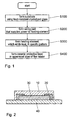
- FIG. 1 is a flowchart of a method of manufacturing a film heater using heat-resistant crystallized glass according to the present invention.
- a heat-resistant crystallized glass 40 is formed under a heating element 30 to stably absorb and dissipate heat generated by the heating element 30 at step S100; a wiring part 20, which supplies power to the heating element 30 and is made of silver Ag, is formed on the heat-resistant crystallized glass 40 at step S200; the heating element 30, which generates heat when electric power is applied thereto, is formed under the wiring part 20 in a specific pattern at step S300; and a ceramic protective layer 10 is formed in the uppermost part of the film heater to protect and insulate the patterns of the heating element 30 and the wiring part 20 at step S400.
- FIG. 2 is a sectional view of the film heater using heat-resistant crystallized glass according to the present invention
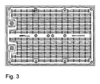
- FIG. 3 is a plan view of the film heater using heat-resistant crystallized glass according to the present invention.
- the heat-resistant crystallized glass 40 which is ceramic glass-based material and has high far-infrared radiation characteristics, is formed under the heating element 30, so that the heat-resistant crystallized glass 40 can stably absorb and dissipate heat generated by the heating element 30, and can tolerate temperatures as high as 800°C, thus having excellent thermal shock resistance.
- the wiring part 20 is formed over the heat-resistant crystallized glass 40, so that power is supplied to the heating element 30 through the wiring part 20, and the plate-shaped heating element 30 is placed under the wiring part 20, so that heat is emitted through a substrate in a specific pattern.
- the ceramic protective layer 10 which is located in the uppermost part of the film heater, can protect and insulate the patterns of the heating element 30 and the wiring part 20.
- the wiring part 20 of the second step is made of silver Ag having low hardness, the width of the wiring part can be minimized in a portion in which it is difficult to form a heating pattern, current load can be minimized at high temperature, and the wiring part 20 can be brought into tight contact with terminals due to the low hardness of silver, thereby allowing current to flow without hindrance.
- the heating element 30 of the third step is formed to include ruthenium RuO 2 , silver-palladium Ag-Pd, and Carbon NanoTubes (CNTs), oxidation is low at a high temperature of 850°C, and thus the manufacturing cost is low, and the heating element 30 has high current density at a high temperature of 550°C, so that the heating element 30 has characteristics in which oxidation does not easily occur and resistance characteristics are not changed.
- CNTs Carbon NanoTubes
- the ceramic protective layer 10 of the fourth step is made to include amorphous glass SiO 2 -A1 2 O 3 -MgO-RO, which can be used in a high-temperature and clean environment because it does not emit particles or gas at a high temperature of 550°C, to which unnecessary foreign material does not stick because it has a very dense and smooth surface, which is easy to clean, and which is advantageous in insulation resistance or withstanding voltage because it has excellent insulation characteristics.
- amorphous glass SiO 2 -A1 2 O 3 -MgO-RO which can be used in a high-temperature and clean environment because it does not emit particles or gas at a high temperature of 550°C, to which unnecessary foreign material does not stick because it has a very dense and smooth surface, which is easy to clean, and which is advantageous in insulation resistance or withstanding voltage because it has excellent insulation characteristics.
- the present invention provides a method of manufacturing a film heater, which is simple, and which provides the film heater, in which heat-resistant crystallized glass is included in the film heater, so that heat, emitted by the heating element, can be stably absorbed and dissipated and the film heater has excellent thermal shock resistance, thus enabling it to tolerate a high temperature of 800°C, and in which a ceramic protective layer is formed, so that the patterns of the heating element and a wiring part can be protected and insulated, with the result that heat, emitted by the heating element, can be efficiently transmitted to a heating target in a conduction or radiation manner.
Landscapes
- Chemical & Material Sciences (AREA)
- Engineering & Computer Science (AREA)
- Nanotechnology (AREA)
- Materials Engineering (AREA)
- Condensed Matter Physics & Semiconductors (AREA)
- General Physics & Mathematics (AREA)
- Physics & Mathematics (AREA)
- Crystallography & Structural Chemistry (AREA)
- Composite Materials (AREA)
- Ceramic Engineering (AREA)
- Inorganic Chemistry (AREA)
- Resistance Heating (AREA)
- Surface Heating Bodies (AREA)
- Glass Compositions (AREA)
Applications Claiming Priority (1)
| Application Number | Priority Date | Filing Date | Title |
|---|---|---|---|
| KR1020070042861A KR100883302B1 (ko) | 2007-05-03 | 2007-05-03 | 내열결정화유리를 이용한 면상 히터의 제조 방법 |
Publications (2)
| Publication Number | Publication Date |
|---|---|
| EP1988747A2 true EP1988747A2 (fr) | 2008-11-05 |
| EP1988747A3 EP1988747A3 (fr) | 2009-06-17 |
Family
ID=39577559
Family Applications (1)
| Application Number | Title | Priority Date | Filing Date |
|---|---|---|---|
| EP07013849A Withdrawn EP1988747A3 (fr) | 2007-05-03 | 2007-07-14 | Procédé pour la fabrication d'un dispositif de chauffage de film à l'aide de verre cristallisé résistant à la chaleur |
Country Status (3)
| Country | Link |
|---|---|
| EP (1) | EP1988747A3 (fr) |
| JP (1) | JP2008277235A (fr) |
| KR (1) | KR100883302B1 (fr) |
Cited By (2)
| Publication number | Priority date | Publication date | Assignee | Title |
|---|---|---|---|---|
| RU2410850C1 (ru) * | 2010-01-25 | 2011-01-27 | Федеральное государственное унитарное предприятие "Обнинское научно-производственное предприятие "Технология" | Способ изготовления электронагревателя |
| CN102318438A (zh) * | 2009-02-17 | 2012-01-11 | 乐金华奥斯有限公司 | 碳纳米管散热片 |
Families Citing this family (1)
| Publication number | Priority date | Publication date | Assignee | Title |
|---|---|---|---|---|
| CN108184507A (zh) * | 2015-04-21 | 2018-06-22 | 吴昊 | 一种农业育苗大棚 |
Family Cites Families (6)
| Publication number | Priority date | Publication date | Assignee | Title |
|---|---|---|---|---|
| GB8704468D0 (en) * | 1987-02-25 | 1987-04-01 | Thorn Emi Appliances | Substrates for supporting electrical components |
| JPH0696847A (ja) * | 1992-09-11 | 1994-04-08 | Matsushita Electric Ind Co Ltd | 面状発熱体およびその製造法 |
| JP2001319761A (ja) * | 2000-05-09 | 2001-11-16 | Narumi China Corp | 遠赤外線ヒーター基板 |
| JP2005071843A (ja) * | 2003-08-26 | 2005-03-17 | Narasaki Sangyo Co Ltd | プレートヒータおよび該ヒータを用いた連続式平面材料表面加熱装置 |
| WO2006122736A2 (fr) * | 2005-05-19 | 2006-11-23 | Fraunhofer-Gesellschaft zur Förderung der angewandten Forschung e.V. | Systeme composite comprenant des nanotubes, son procede de production, et son utilisation dans des elements de chauffage |
| KR200399652Y1 (ko) * | 2005-08-04 | 2005-10-26 | 김종만 | 후막형 발열체가 구비된 핫 플레이트 |
-
2007
- 2007-05-03 KR KR1020070042861A patent/KR100883302B1/ko not_active Expired - Fee Related
- 2007-07-14 EP EP07013849A patent/EP1988747A3/fr not_active Withdrawn
- 2007-07-27 JP JP2007195718A patent/JP2008277235A/ja active Pending
Cited By (3)
| Publication number | Priority date | Publication date | Assignee | Title |
|---|---|---|---|---|
| CN102318438A (zh) * | 2009-02-17 | 2012-01-11 | 乐金华奥斯有限公司 | 碳纳米管散热片 |
| US9237606B2 (en) | 2009-02-17 | 2016-01-12 | Lg Hausys, Ltd. | Carbon nanotube sheet heater |
| RU2410850C1 (ru) * | 2010-01-25 | 2011-01-27 | Федеральное государственное унитарное предприятие "Обнинское научно-производственное предприятие "Технология" | Способ изготовления электронагревателя |
Also Published As
| Publication number | Publication date |
|---|---|
| JP2008277235A (ja) | 2008-11-13 |
| KR20080097698A (ko) | 2008-11-06 |
| EP1988747A3 (fr) | 2009-06-17 |
| KR100883302B1 (ko) | 2009-02-17 |
Similar Documents
| Publication | Publication Date | Title |
|---|---|---|
| KR102461509B1 (ko) | 히팅필름 | |
| JP2017525122A (ja) | Ptc抵抗構造を有する平面加熱素子 | |
| EA201290240A1 (ru) | Электронагреваемая курительная система с улучшенным нагревателем | |
| TW200812422A (en) | Heating element for a hot air device | |
| JP2015152218A (ja) | 流体加熱装置 | |
| TW200936973A (en) | Moisture resistant layered sleeve heater and method of manufacture thereof | |
| KR20130128939A (ko) | 2차원적으로 배선된 열선을 포함하는 세라믹 히터 | |
| CN103702833B (zh) | 微结构化的热冲压模具 | |
| KR101832193B1 (ko) | 용접예열히터 | |
| CN110381613A (zh) | 一种纳米面状电阻膜金属电热装置 | |
| KR100883302B1 (ko) | 내열결정화유리를 이용한 면상 히터의 제조 방법 | |
| CN105972570B (zh) | 蒸汽发生器及蒸汽设备 | |
| US11828490B2 (en) | Ceramic heater for heating water in an appliance | |
| JP2015035413A (ja) | ヒータ | |
| KR102014114B1 (ko) | 다수의 평면 구역에 적합한 평판형 히터 장치 | |
| WO2017117873A1 (fr) | Élément chauffant à film épais à deux côtés présentant une conductivité thermique élevée | |
| CN206380107U (zh) | 一种石墨烯纳米碳管高温陶瓷合金发热板 | |
| KR20210153577A (ko) | 건축용 복사히터 모듈 및 이를 포함하는 건축용 복사히터 | |
| KR20090088024A (ko) | 원적외선 글라스 히터를 구비한 그릴 | |
| JP5592706B2 (ja) | シースヒータのリード線接続端子 | |
| JP7792758B2 (ja) | 熱輻射素子、熱輻射素子モジュール、及び熱輻射光源 | |
| JP5600479B2 (ja) | シースヒータのリード線接続端子 | |
| JP2021507536A (ja) | 伝熱管を用いて電極を電気的に切り離された形で均一に温度制御するシステム及びそのようなシステムを備えた処理室 | |
| JPH05500435A (ja) | シリコン加熱エレメント | |
| KR20230147678A (ko) | 시스 히터 및 이를 갖는 기판 지지 장치 |
Legal Events
| Date | Code | Title | Description |
|---|---|---|---|
| PUAI | Public reference made under article 153(3) epc to a published international application that has entered the european phase |
Free format text: ORIGINAL CODE: 0009012 |
|
| AK | Designated contracting states |
Kind code of ref document: A2 Designated state(s): AT BE BG CH CY CZ DE DK EE ES FI FR GB GR HU IE IS IT LI LT LU LV MC MT NL PL PT RO SE SI SK TR |
|
| AX | Request for extension of the european patent |
Extension state: AL BA HR MK RS |
|
| PUAL | Search report despatched |
Free format text: ORIGINAL CODE: 0009013 |
|
| AK | Designated contracting states |
Kind code of ref document: A3 Designated state(s): AT BE BG CH CY CZ DE DK EE ES FI FR GB GR HU IE IS IT LI LT LU LV MC MT NL PL PT RO SE SI SK TR |
|
| AX | Request for extension of the european patent |
Extension state: AL BA HR MK RS |
|
| AKX | Designation fees paid | ||
| STAA | Information on the status of an ep patent application or granted ep patent |
Free format text: STATUS: THE APPLICATION IS DEEMED TO BE WITHDRAWN |
|
| 18D | Application deemed to be withdrawn |
Effective date: 20091218 |
|
| REG | Reference to a national code |
Ref country code: DE Ref legal event code: 8566 |