EP1989115B1 - Dispositif de remplissage d'un récipient - Google Patents
Dispositif de remplissage d'un récipient Download PDFInfo
- Publication number
- EP1989115B1 EP1989115B1 EP07711683A EP07711683A EP1989115B1 EP 1989115 B1 EP1989115 B1 EP 1989115B1 EP 07711683 A EP07711683 A EP 07711683A EP 07711683 A EP07711683 A EP 07711683A EP 1989115 B1 EP1989115 B1 EP 1989115B1
- Authority
- EP
- European Patent Office
- Prior art keywords
- conveyor
- station
- filling device
- filling
- box conveyor
- Prior art date
- Legal status (The legal status is an assumption and is not a legal conclusion. Google has not performed a legal analysis and makes no representation as to the accuracy of the status listed.)
- Active
Links
Images
Classifications
-
- B—PERFORMING OPERATIONS; TRANSPORTING
- B65—CONVEYING; PACKING; STORING; HANDLING THIN OR FILAMENTARY MATERIAL
- B65B—MACHINES, APPARATUS OR DEVICES FOR, OR METHODS OF, PACKAGING ARTICLES OR MATERIALS; UNPACKING
- B65B25/00—Packaging other articles presenting special problems
- B65B25/14—Packaging paper or like sheets, envelopes, or newspapers, in flat, folded, or rolled form
- B65B25/145—Packaging paper or like sheets, envelopes, or newspapers, in flat, folded, or rolled form packaging folded articles
-
- B—PERFORMING OPERATIONS; TRANSPORTING
- B65—CONVEYING; PACKING; STORING; HANDLING THIN OR FILAMENTARY MATERIAL
- B65B—MACHINES, APPARATUS OR DEVICES FOR, OR METHODS OF, PACKAGING ARTICLES OR MATERIALS; UNPACKING
- B65B25/00—Packaging other articles presenting special problems
- B65B25/14—Packaging paper or like sheets, envelopes, or newspapers, in flat, folded, or rolled form
-
- B—PERFORMING OPERATIONS; TRANSPORTING
- B65—CONVEYING; PACKING; STORING; HANDLING THIN OR FILAMENTARY MATERIAL
- B65B—MACHINES, APPARATUS OR DEVICES FOR, OR METHODS OF, PACKAGING ARTICLES OR MATERIALS; UNPACKING
- B65B25/00—Packaging other articles presenting special problems
- B65B25/14—Packaging paper or like sheets, envelopes, or newspapers, in flat, folded, or rolled form
- B65B25/141—Packaging paper or like sheets, envelopes, or newspapers, in flat, folded, or rolled form packaging flat articles in boxes
- B65B25/143—Packaging paper or like sheets, envelopes, or newspapers, in flat, folded, or rolled form packaging flat articles in boxes by introducing successive articles
-
- B—PERFORMING OPERATIONS; TRANSPORTING
- B65—CONVEYING; PACKING; STORING; HANDLING THIN OR FILAMENTARY MATERIAL
- B65B—MACHINES, APPARATUS OR DEVICES FOR, OR METHODS OF, PACKAGING ARTICLES OR MATERIALS; UNPACKING
- B65B57/00—Automatic control, checking, warning, or safety devices
- B65B57/10—Automatic control, checking, warning, or safety devices responsive to absence, presence, abnormal feed, or misplacement of articles or materials to be packaged
-
- B—PERFORMING OPERATIONS; TRANSPORTING
- B65—CONVEYING; PACKING; STORING; HANDLING THIN OR FILAMENTARY MATERIAL
- B65H—HANDLING THIN OR FILAMENTARY MATERIAL, e.g. SHEETS, WEBS, CABLES
- B65H2404/00—Parts for transporting or guiding the handled material
- B65H2404/20—Belts
- B65H2404/26—Particular arrangement of belt, or belts
- B65H2404/261—Arrangement of belts, or belt(s) / roller(s) facing each other for forming a transport nip
- B65H2404/2613—Means for changing the transport path, e.g. deforming, lengthening
-
- B—PERFORMING OPERATIONS; TRANSPORTING
- B65—CONVEYING; PACKING; STORING; HANDLING THIN OR FILAMENTARY MATERIAL
- B65H—HANDLING THIN OR FILAMENTARY MATERIAL, e.g. SHEETS, WEBS, CABLES
- B65H2701/00—Handled material; Storage means
- B65H2701/10—Handled articles or webs
- B65H2701/17—Nature of material
- B65H2701/176—Cardboard
- B65H2701/1766—Cut-out, multi-layer, e.g. folded blanks or boxes
Definitions
- the present invention relates to a device for filling a container, with folding boxes, of the type comprising a tableting station, a filling station, a box conveyor able to transport boxes coming out of a folder-gluer and routing them from said tableting station to the filling station along a routing path.
- the document CH 659627 A describes a filling device of the aforementioned type.
- Such a device is provided to fill alone and securely containers with folding boxes while ensuring the operator the ability to monitor all operations from the tablecloth until filling.
- the operator must periodically prepare folding carton samples for production quality control purposes, in particular to meet the requirements of ISO 9000 standards, he shall recover such samples, either upstream of the filling device, before the treatment of the boxes by the filling device, that is to say at the exit of the folder-gluer, or downstream of the filling device, that is to say after the treatment of the boxes by the device filling.
- An object of the present invention is to overcome the aforementioned drawbacks by proposing a filling device that avoids sampling samples of folding boxes both upstream of the filling device and downstream.
- the present invention relates to a device for filling a container with folding boxes according to claim 1.
- the proposed solution is particularly simple, both from the point of view of the manufacture and the use of the device.
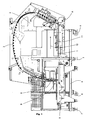
- FIG. 1 is a general front view of a filling device according to the prior art
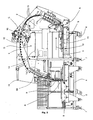
- FIG. 2 is a general front view of a filling device according to the invention.
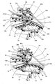
- FIG. 3 is a detailed view of the sampling station in a first position
- FIG. 4 is a detailed view of the sampling station in a second position.
- the figure 1 is a general front view of a filling device according to the prior art placed at the exit of a folder-gluer 1.
- the filling device comprises a frame 2 constituted by a vertical support plate on which is mounted a conveyor belt (or belts) 3 for conveying folding boxes (not shown) of a tableting station A to a filling station B according to a routing path Ta of which at least a portion Ta "is located above the horizontal plane passing through the median axis of said folder-gluer 1 (shown in phantom)
- the frame 2 is fixed on a base 4 supporting a belt conveyor 5 placed perpendicular to the central axis of the folder-gluer 1.
- the filling station B is also mounted on the base 4.
- the belt conveyor 5 is driven by an electric motor which allows controlling the feeding speed of the filling device according to the speed of the last roll of the receiving station of the folder-gluer 1, thus facilitating the connection between the folder-gluer and the filling device.
- rollers 6 and 7 brakes allowing the introduction of the filling device at the exit of the folder-gluer 1.
- the folding boxes are folded out of the folder-gluer 1 and come against a stop 11 of the filling device intended to retain them, so that the belt conveyor 5 driven in the direction of the arrow 12 brings them in a sheet into the tabletting station A.
- the abutment 11 is for example a plate made of a transparent synthetic material.
- the folding boxes are then conveyed by the box conveyor 3 to the filling station B where a container, otherwise called a container (not shown), waits to be filled by a filling arm 9.
- the container is then moved on a table 8, where it can be evacuated.
- the filling device according to the invention differs from the filling device of the prior art in that it comprises a sampling station C, a recovery station D, a second box conveyor 10 able to transport boxes conveyed by the first box conveyor 3 and transferring them from the sampling station C to the recovery station D along a transfer path Tt.
- the recovery station D is arranged under the sampling station C and comprises a shelf 13 fixed through an opening of the frame 2, suitable receiving a tray (not shown) for recovering folding carton samples.
- the second box conveyor 10 is also a band conveyor arranged between the sampling station C and the recovery station D so as to be able to recover the sampled boxes, that is to say the boxes diverted by the station from sampling C, and transfer them to the recovery tank according to a transfer path Tt substantially straight.
- the first 3 and the second box conveyor are mounted on two portions 14a, 14b of the vertical support plate 2.
- the first box conveyor 3 comprises an upper single conveyer 3a cooperating with a lower single conveyor 3b, the upper single conveyor 3a performs a substantially curvilinear lower path, corresponding to an upper path of the lower single conveyor 3b, and coinciding with the path Ta routing.
- Support rollers 15, 15b are mounted on the vertical support plate 2 along the path Ta to guide and support the belts of the first can conveyor 3.
- the belt of the upper conveyor 3a is then returned in an upper return path in being guided by rollers 16 where it passes through different energizing devices and a drive shaft before returning to its lower path.
- the second box conveyor 10 also includes an upper single conveyor 10a cooperating with an intermediate portion of the lower single conveyor 3b, the upper conveyor 10a performs a substantially straight lower path in a downwardly oblique plane at an angle to the horizontal plane. , corresponding to an intermediate path of the lower conveyor 3b coinciding with the transfer path Tt.
- the angle is between 20 ° and 30 °, for example 25 °.
- the belts of the second box conveyor 10 pass between a ramp of support rollers 38 and a ramp of support rollers (not visible) respectively mounted at the rear 14b and at the front 14a. of the vertical support plate 2.
- the routing path Ta and the transfer path Tt are located in the same vertical plane.
- the routing path Ta delimits a substantially convex surface such that the transfer path Tt is located within this convex surface.
- the first box conveyor 3 is divided into two distinct parts: a rear portion 33a, 33b mounted at the rear 14b of the vertical support plate and a front portion 37a, 37b mounted at the front 14a of the vertical support plate.
- the rear portion 33a, 33b of the first box conveyor 3 ends with a pair of front end rollers 32a, 32b and the front portion 37a, 37b begins with a pair of rear end rollers 36a, 36b.
- said pair of rear end rollers 36a, 36b is situated behind said second box conveyor 10, that is to say that a box diverted towards the second box conveyor 10 passes under the pair of rollers.
- rear end 36a, 36b is situated behind said second box conveyor 10, that is to say that a box diverted towards the second box conveyor 10 passes under the pair of rollers.
- the sampling station is shown in a first position where the lower path of the belt of the upper conveyor 3a describes an upwardly oriented upper loop and located above the second can conveyor 10 being successively guided by a roller 32a d front end of the rear portion 33a of the upper conveyor, three upper rollers 34a, 34b and 34c, and then returned by a rear end roller 36a of the front portion 37a of the upper conveyor.
- This deflection loop has a substantially T-shaped shape, that is to say that the belt of the upper conveyor is wound on a front portion of the periphery of the roller 32a before being returned by the roller 34a located behind by relative to the roller 32a towards the roller 34c located in front of the roller 36a, the roller 34b supporting the belt between the rollers 34a and 34c.
- the belt is then wound on a rear portion of the periphery of the roller 36a.
- the support rollers 15 of the routing path Ta are mounted on the two-part vertical support plate 14a and 14b.
- the ramp of support rollers 38 and the ramp of support rollers of the transfer path Tt are mounted on the vertical front support plate 14a.
- the front end roller 32a of the rear portion and the upper roller 34b are both mounted on a lever upper 20 controlled by the rod of a cylinder 41
- the upper roller 34a is mounted on an intermediate lever 21 controlled by the rod of a cylinder 42
- the roller 36a rear end of the front part and the upper roller 34c are both mounted on a lever 22.
- the three levers 20, 21 and 22 and the two cylinders 41 and 42 are all mounted on a bracket 39 integral with the vertical support plate, the bracket 39 having the general shape of T.
- the horizontal portion of the bracket 39 forms a mounting plate for the levers 20, 21, 22 and the cylinders 41 and 42
- the vertical portion of the bracket 39 forms a bridge connecting the rear 14b and the before 14a of the vertical support plate.
- the sampling station is shown in a second position where the lower path of the belt of the upper conveyor 3a also describes an upper loop oriented upwards but a part of which is situated at the same level as the second conveyor of boxes 10, in being successively guided by the front end roller 32a of the rear portion 33a of the upper conveyor, the roller 34b, the rollers 34a and 34c, and then returned by the rear end roller 36a of the front portion 37a of the upper conveyor.
- the deflection loop here has a general shape formed from an inverted C shape (like a C seen in a mirror) having a large opening, followed by a C shape having a smaller aperture, that is, that is to say that the belt of the upper conveyor is wound on the front part of the periphery of the roller 32a before being returned by the roller 34a located behind the roller 32a towards the roller 34c located in front of the roller 36a, the roller 34b here to press the belt between the rollers 32a and 34a, the belt is then wound on the rear portion of the periphery of the roller 36a.
- the front portion 37a, 37b of the first box conveyor 3 is fixedly mounted on the vertical front support plate 14a so that the lower path of the upper conveyor 3a and the upper path of the lower conveyor 3b do not change in this front portion 37a, 37b, regardless of the position of the sampling station C.
- the rear portion 33a, 33b of the first box conveyor 3 is movably mounted on the rear vertical support plate 14b, so as to be able to modifying the lower path of the upper conveyor 3a and the upper path of the lower conveyor 3b, depending on the position of the sampling station.
- the belts of the upper conveyor 3a and lower 3b are supported on support rollers 15a of a lower lever 30 also carrying the front end roller 32b of the rear portion of the lower conveyor.
- the lower lever 30 is then in a high position such that the rear portion 33b is aligned with the front portion 37b of the lower conveyor 3b, while the front end roller 32a of the rear portion of the upper carrier carried by the upper lever 20 is in a position such that the rear portion 33a is aligned with the front portion 37a of the upper conveyor 3a.
- the lower lever 30 is pivotally mounted about an axis 35 supported by a bearing of the rear vertical support plate 14b, the free end of the lever 30 carried the front end roller 32b.
- the actuating rod of a lower cylinder (not visible) is secured to the lever 30, approximately in the middle of the latter, between the axis 35 and the front end roller 32b, the lower cylinder being mounted on the vertical plate rear support 14b.
- the point of divergence 71 of the belts of the rear portion 33a, 33b of the first can carrier is located a short distance from the point of convergence 70 of the belts of the front portion 37a, 37b of the first can carrier. This distance is less than the minimum length of the boxes to be treated by the filling device according to the invention, which allows the boxes to be transported along the routing path Ta without breaking the drive.
- the point of divergence 71 corresponds to the last point of contact of the belts after their passage between the pair of front end rollers 32a, 32b, while the point of convergence 70 corresponds to the first point of contact of the belts before their passage between the pair. of rear end rollers 36a, 36b.
- the belts of the upper conveyor 3a and lower 3b are supported on support rollers 15b of the vertical plate of rear support 14b.
- the lower lever 30 is then in a low position such that the rear portion 33b of the lower conveyor 3b is aligned with the intermediate portion of the lower conveyor 3b cooperating with the upper single conveyor 10a of the second can conveyor 10, while the roller the front end 32a is in a position such that the rear portion 33a of the upper conveyor 3a is aligned with the lower portion of the upper single conveyor 10a. Thanks to these arrangements, the second box conveyor 10 is perfectly aligned with the rear portion 33a, 33b of the first box conveyor 3.
- the rollers 15a of the lower lever 30 are retracted under the rollers 15b of the vertical plate of Rear support passing between these and the point of convergence 72 of the second conveyor belt boxes 10 is located a short distance from the point of divergence 73 of the belts of the rear portion 33a, 33b of the first carrier boxes.
- the point of convergence 72 corresponds to the first point of contact of the belts before they pass between the ramp of support rollers 38 and the ramp of support rollers
- the point of divergence 73 corresponds to the last point of contact of the belts after their passage between the pair of front end rollers 32a, 32b.
- the sampling station C is provided with means for deflecting the rear portion 33a, 33b of the first box conveyor 3 comprising, the lower lever 30 controlled by the lower jack, the lever upper 20 controlled by the cylinder 41 and the intermediate lever 21 controlled by the cylinder 42.
- the control of the cylinders is synchronized.
- the rod of the lower cylinder out, on leaving it rotates the lower lever 30 in the clockwise direction about its axis 35.
- the lower lever 30 pivots until the front end roller 32b, initially located in the extension of the support roller ramp 38 of the second conveyor 10, is finally in the extension of the rear end roller 36b.
- the rod of the cylinder 41 returns, on returning it rotates the upper lever 20 in the counterclockwise direction about a supported axis 43 by a first bearing arranged on the mounting plate of the bracket 39.
- the upper lever 20 is generally L-shaped, i.e.
- the axis 43 is on the longest part of the upper lever 20, opposite the adjacent part, while the front end roller 32a and the upper roller 34b are on the shortest part of the lever higher, respectively opposite to the adjacent part and in the adjacent part.
- the rod of the cylinder 41 is secured to the upper lever 20 approximately in the middle of the longest part, between the axis 43 and the upper roller 34b.
- the upper lever 20 pivots until the front end roller 32a, initially situated in the extension of the ramp of support rollers of the second conveyor 10, is finally in the extension of the rear end roller 36a.
- the upper roller 34b moves from a first support position to a second support position of the deflection loop.
- the rod of the cylinder 42 returns, on returning it rotates the intermediate lever 21 in the counterclockwise direction about an axis 44 supported by a second bearing arranged on the mounting plate of the bracket 39.
- the intermediate lever 21 has the general shape of a 1, one end is secured to the rod of the cylinder and the other end receives the upper roller 34a, the axis 44 is between the two ends.
- the intermediate lever 21 pivots until the upper roller 34a moves from a first position to a second support position of the deflection loop, the lever 21 here acting as a belt tensioner.
- the operator programs on a control and control panel 50 (see FIG. figure 2 ) the desired number of boxes folded per Nb / e sample and the desired number of samples per container N e / r .
- the sampling station C is in the second position, N b / e folded boxes leave the tableting station A and are conveyed by the first conveyor 3. Arrival in the sampling station C, the N b / e boxes are diverted to the second conveyor 10 to be transferred to the recovery station D.
- the sampling station C is in the first position so that to send the following boxes to filling station B.
- the first and second steps are repeated N e / r times per container.
- the distance to be left between the N b / e first boxes and the following boxes is dependent on the reaction time of the moving parts of the sampling station C. Because the only parts set in motion are the levers 20, 21 and 30 with their respective cylinder rod, this set has a low mass and low inertia, which allows to minimize this reaction time.
- the invention makes it possible to direct all the boxes towards the recovery station D, which avoids the operator having to intervene manually in the filling station B.
- this loop is also a "buffer zone" to absorb the elongation of the upper conveyor belt, without this elongation is reflected downstream in the front portion of the upper carrier.
Landscapes
- Engineering & Computer Science (AREA)
- Mechanical Engineering (AREA)
- Container Filling Or Packaging Operations (AREA)
- Closing Of Containers (AREA)
- Branching, Merging, And Special Transfer Between Conveyors (AREA)
- Making Paper Articles (AREA)
- Wrapping Of Specific Fragile Articles (AREA)
- Basic Packing Technique (AREA)
Description
- La présente invention concerne un dispositif de remplissage d'un récipient, avec des boîtes pliantes, du type comprenant une station de mise en nappe, une station de remplissage, un transporteur de boîtes apte à transporter des boîtes sortant d'une plieuse-colleuse et à les acheminer de ladite station de mise en nappe vers la station de remplissage selon un trajet d'acheminement.
- Le document
CH 659627 A - En amont du dispositif de remplissage, il est connu des dispositifs d'échantillonnage automatique qui évite à l'opérateur de prélever manuellement des échantillons de boîtes pliantes à la sortie d'une plieuse-colleuse, voir par exemple le document
DE 19502676 A . Toutefois, ce type connu de dispositif d'échantillonnage présente, en plus d'une certaine complexité technique, l'inconvénient de ne pouvoir prélever qu'une seule boîte à la fois, ce qui veut dire que chaque échantillon est constitué d'une boîte unique. - En aval du dispositif de remplissage, c'est l'opérateur lui-même qui doit prélever dans les récipients des échantillons de boîtes pliantes, ce qui n'est pas compatible avec les systèmes de production à haute cadence rencontrés dans l'industrie de l'emballage. En effet, une plieuse-colleuse de celles qui peuvent alimenter un dispositif de remplissage du type précité est capable de produire jusqu'à 200000 boîtes par heure.
Le documentUS 4 161 092 divulgue un dispositif correspondant au préambule de la revendication 1. - Un but de la présente invention est de remédier aux inconvénients précités en proposant un dispositif de remplissage qui permet d'éviter un prélèvement d'échantillons de boites pliantes aussi bien en amont du dispositif de remplissage qu'en aval.
- A cet effet, la présente invention a pour objet un dispositif de remplissage d'un récipient avec des boîtes pliantes selon la revendication 1.
- Comme on le constatera au cours de la description qui suit, la solution proposée est particulièrement simple, aussi bien du point de vue de la fabrication que de l'utilisation du dispositif.
- D'autres particularités et avantages de la présente invention apparaîtront au cours de la description qui va suivre et qui sera faite à l'aide des dessins annexés qui illustrent, schématiquement et à titre d'exemple, une forme d'exécution du dispositif de remplissage objet de la présente invention.
- - la
figure 1 est une vue générale de face d'un dispositif de remplissage selon l'art antérieur; - - la
figure 2 est une vue générale de face d'un dispositif de remplissage selon l'invention; - - la
figure 3 est une vue détaillée de la station d'échantillonnage dans une première position; - - la
figure 4 est une vue détaillée de la station d'échantillonnage dans une seconde position. - La
figure 1 est une vue générale de face d'un dispositif de remplissage selon l'art antérieur placé à la sortie d'une plieuse-colleuse 1. - Le dispositif de remplissage comprend un bâti 2 constitué par une plaque verticale de support, sur lequel est monté un transporteur à bandes (ou courroies) 3 destiné à acheminer des boîtes pliantes (non représentées) d'une station de mise en nappe A vers une station de remplissage B selon un trajet d'acheminement Ta dont au moins une partie Ta" est située au-dessus du plan horizontal passant par l'axe médian de ladite plieuse-colleuse 1 (représentée en traits interrompus). Le bâti 2 est fixé sur une embase 4 supportant un convoyeur à courroies 5 placé perpendiculairement, par rapport à l'axe médian de la plieuse-colleuse 1. La station de remplissage B est elle aussi montée sur l'embase 4. Le convoyeur à courroies 5 est entraîné par un moteur électrique qui permet de commander la vitesse d'alimentation du dispositif de remplissage en fonction de la vitesse du dernier rouleau de la station de réception de la plieuse-colleuse 1, facilitant ainsi la liaison entre la plieuse-colleuse et le dispositif de remplissage. L'embase 4 est munie de roulettes 6 et de freins 7 autorisant la mise en place du dispositif de remplissage à la sortie de la plieuse-colleuse 1.
- Les boîtes pliantes sortent en nappe de la plieuse-colleuse 1 et arrivent contre une butée 11 du dispositif de remplissage destinée à les retenir, de façon que le convoyeur à courroies 5 entraîné dans le sens de la flèche 12 les amène en nappe jusque dans la station de mise en nappe A. La butée 11 est par exemple une plaque réalisée dans un matériau synthétique transparent. Les boîtes pliantes sont ensuite acheminées par le transporteur de boîtes 3 vers la station de remplissage B où un récipient, autrement appelé un container (non représenté), attend d'être rempli par un bras de remplissage 9. Le récipient est ensuite déplacé sur une table 8, où il peut être évacué.
- Le dispositif de remplissage selon l'invention, illustré à la
figure 2 , diffère du dispositif de remplissage de l'art antérieur en ce qu'il comprend une station d'échantillonnage C, une station de récupération D, un second transporteur de boîtes 10 apte à transporter des boîtes acheminées par le premier transporteur de boîtes 3 et à les transférer de la station d'échantillonnage C vers la station de récupération D selon un trajet de transfert Tt. Une description plus détaillée de la station d'échantillonnage C sera donnée en relation avec lesfigures 3 et 4 . La station de récupération D est agencée sous la station d'échantillonnage C et comprend une étagère 13 fixée au travers d'une ouverture du bâti 2, apte à recevoir un bac (non représenté) pour la récupération d'échantillons de boîtes pliantes. Le second transporteur de boîtes 10 est également un transporteur à bandes agencé entre la station d'échantillonnage C et la station de récupération D de façon à pouvoir récupérer les boîtes échantillonnées, c'est-à-dire les boîtes déviées par la station d'échantillonnage C, et les transférer vers le bac de récupération selon un trajet de transfert Tt sensiblement rectiligne. Le premier 3 et le second 10 transporteur de boîtes sont montés sur deux parties 14a, 14b de la plaque verticale de support 2. - Comme mieux visible sur les
figures 3 et 4 , le premier transporteur de boîtes 3 comprend un transporteur unique supérieur 3a coopérant avec un transporteur unique inférieur 3b, le transporteur unique supérieur 3a effectue un trajet inférieur sensiblement curviligne, en correspondance avec un trajet supérieur du transporteur unique inférieur 3b, et coïncidant avec le trajet d'acheminement Ta. Des galets de support 15, 15b sont montés sur la plaque verticale de support 2 le long du trajet Ta pour guider et supporter les courroies du premier transporteur de boîtes 3. La courroie du transporteur supérieur 3a est ensuite renvoyée selon un trajet de retour supérieur en étant guidée par des galets 16 où elle passe par différents dispositifs de mise sous tension et un axe d'entraînement avant le retour vers son trajet inférieur. Le second transporteur de boîtes 10 comprend également un transporteur unique supérieur 10a coopérant avec une partie intermédiaire du transporteur unique inférieur 3b, le transporteur supérieur 10a effectue un trajet inférieur sensiblement rectiligne dans un plan oblique vers le bas avec un certain angle par rapport au plan horizontal, en correspondance avec un trajet intermédiaire du transporteur inférieur 3b coïncidant avec le trajet de transfert Tt. De préférence, l'angle est compris entre 20° et 30°, par exemple 25°. Le long du trajet de transfert Tt, les courroies du second transporteur de boîtes 10 passent entre une rampe de galets de support 38 et une rampe de galets d'appui (non visible) montées respectivement à l'arrière 14b et à l'avant 14a de la plaque verticale de support 2. Ainsi, le trajet d'acheminement Ta et le trajet de transfert Tt sont situés dans un même plan vertical. De plus, on notera que le trajet d'acheminement Ta délimite une surface essentiellement convexe tel que le trajet de transfert Tt est situé à l'intérieur de cette surface convexe. - Au niveau de la station d'échantillonnage C, le premier transporteur de boîtes 3 est divisé en deux parties distinctes : une partie arrière 33a, 33b montée à l'arrière 14b de la plaque verticale de support et une partie avant 37a, 37b montée à l'avant 14a de la plaque verticale de support. La partie arrière 33a, 33b du premier transporteur de boîtes 3 se termine par une paire de galets d'extrémité avant 32a ,32b et la partie avant 37a, 37b commence par une paire de galets d'extrémité arrière 36a, 36b. Avantageusement, ladite paire de galets d'extrémité arrière 36a, 36b est située en arrière dudit second transporteur de boîtes 10, c'est-à-dire qu'une boîte déviée vers le second transporteur de boîtes 10 passe sous la paire de galets d'extrémité arrière 36a, 36b.
- Sur la
figure 3 , la station d'échantillonnage est montrée dans une première position où le trajet inférieur de la courroie du transporteur supérieur 3a décrit une boucle supérieure orientée vers le haut et située au dessus du second transporteur de boîtes 10 en étant successivement guidé par un galet 32a d'extrémité avant de la partie arrière 33a du transporteur supérieur, trois galets supérieurs 34a, 34b et 34c, puis renvoyé par un galet 36a d'extrémité arrière de la partie avant 37a du transporteur supérieur. Cette boucle de déviation présente une forme sensiblement en T, c'est-à-dire que la courroie du transporteur supérieur s'enroule sur une partie avant de la périphérie du galet 32a avant d'être renvoyée par le galet 34a situé en arrière par rapport au galet 32a vers le galet 34c situé en avant du galet 36a, le galet 34b venant supporter la courroie entre les galets 34a et 34c. La courroie est ensuite enroulée sur une partie arrière de la périphérie du galet 36a. Les galets de support 15 du trajet d'acheminement Ta sont montés sur la plaque verticale de support en deux parties 14a et 14b. La rampe de galets de support 38 et la rampe de galets d'appui du trajet de transfert Tt sont montés sur la plaque verticale de support avant 14a. Par contre, le galet 32a d'extrémité avant de la partie arrière et le galet supérieur 34b sont tous deux montés sur un levier supérieur 20 commandé par la tige d'un vérin 41, le galet supérieur 34a est monté sur un levier intermédiaire 21 commandé par la tige d'un vérin 42, tandis que le galet 36a d'extrémité arrière de la partie avant et le galet supérieur 34c sont tous deux montés sur un levier 22. Les trois leviers 20, 21 et 22 ainsi que les deux vérins 41 et 42 sont tous montés sur une potence 39 solidaire de la plaque verticale de support, la potence 39 ayant la forme générale d'un T. La partie horizontale de la potence 39 forme une platine de fixation pour les leviers 20, 21, 22 et les vérins 41 et 42, tandis que la partie verticale de la potence 39 forme un pont reliant l'arrière 14b et l'avant 14a de la plaque verticale de support. - Sur la
figure 4 , la station d'échantillonnage est montrée dans une seconde position où le trajet inférieur de la courroie du transporteur supérieur 3a décrit aussi une boucle supérieure orientée vers le haut mais dont une partie est située au même niveau que le second transporteur de boîtes 10, en étant successivement guidée par le galet 32a d'extrémité avant de la partie arrière 33a du transporteur supérieur, le galet 34b, les galet 34a et 34c, puis renvoyé par le galet 36a d'extrémité arrière de la partie avant 37a du transporteur supérieur. La boucle de déviation présente ici une forme générale constituée à partir d'une forme en C inversé (comme un C vu dans un miroir) présentant une grande ouverture, suivie d'une forme en C présentant une ouverture plus petite, c'est-à-dire que la courroie du transporteur supérieur s'enroule sur la partie avant de la périphérie du galet 32a avant d'être renvoyée par le galet 34a situé en arrière du galet 32a vers le galet 34c situé en avant du galet 36a, le galet 34b venant ici appuyer sur la courroie entre les galets 32a et 34a, la courroie est ensuite enroulée sur la partie arrière de la périphérie du galet 36a. - La partie avant 37a, 37b du premier transporteur de boîtes 3 est montée fixe sur la plaque verticale de support avant 14a de sorte que le trajet inférieur du transporteur supérieur 3a et le trajet supérieur du transporteur inférieur 3b ne changent pas dans cette partie avant 37a, 37b, quelle que soit la position de la station d'échantillonnage C. Par contre, la partie arrière 33a, 33b du premier transporteur de boîtes 3 est montée mobile sur la plaque verticale de support arrière 14b, de manière à pouvoir modifier le trajet inférieur du transporteur supérieur 3a et le trajet supérieur du transporteur inférieur 3b, en fonction de la position de la station d'échantillonnage. En effet, quand la station d'échantillonnage C est dans la première position illustrée sur la
figure 3 , les courroies du transporteur supérieur 3a et inférieur 3b sont en appui sur des galets de support 15a d'un levier inférieur 30 portant aussi le galet d'extrémité avant 32b de la partie arrière du transporteur inférieur. Le levier inférieur 30 se trouve alors dans une position haute telle que la partie arrière 33b est alignée avec la partie avant 37b du transporteur inférieur 3b, tandis que le galet d'extrémité avant 32a de la partie arrière du transporteur supérieur porté par le levier supérieur 20 se trouve dans une position telle que la partie arrière 33a est alignée avec la partie avant 37a du transporteur supérieur 3a. Le levier inférieur 30 est monté pivotant autour d'un axe 35 supporté par un palier de la plaque verticale de support arrière 14b, l'extrémité libre du levier 30 porté le galet d'extrémité avant 32b. La tige d'actionnement d'un vérin inférieur (non visible) est assujettie au levier 30, approximativement au milieu de ce dernier, entre l'axe 35 et le galet d'extrémité avant 32b, le vérin inférieur étant monté sur la plaque verticale de support arrière 14b. Dans cette position, le point de divergence 71 des courroies de la partie arrière 33a, 33b du premier transporteur de boîtes est situé à une courte distance du point de convergence 70 des courroies de la partie avant 37a, 37b du premier transporteur de boîtes. Cette distance est inférieure à la longueur minimum des boîtes destinées à être traitées par le dispositif de remplissage selon l'invention, ce qui permet de transporter les boîtes le long du trajet d'acheminement Ta sans rupture d'entraînement. Le point de divergence 71 correspond au dernier point de contact des courroies après leur passage entre la paire de galets d'extrémité avant 32a, 32b, tandis que le point de convergence 70 correspond au premier point de contact des courroies avant leur passage entre la paire de galets d'extrémité arrière 36a, 36b. - Quand la station d'échantillonnage C est dans la seconde position illustrée sur la
figure 4 , les courroies du transporteur supérieur 3a et inférieur 3b sont en appui sur des galets de support 15b de la plaque verticale de support arrière 14b. Le levier inférieur 30 se trouve alors dans une position basse telle que la partie arrière 33b du transporteur inférieur 3b est alignée avec la partie intermédiaire du transporteur inférieur 3b coopérant avec le transporteur unique supérieur 10a du second transporteur de boîtes 10, tandis que le galet d'extrémité avant 32a se trouve dans une position telle que la partie arrière 33a du transporteur supérieur 3a est alignée avec la partie inférieure du transporteur unique supérieur 10a. Grâce à ces dispositions, le second transporteur de boîtes 10 est parfaitement aligné avec la partie arrière 33a, 33b du premier transporteur de boîtes 3. Dans cette position, les galets 15a du levier inférieur 30 sont escamotés sous les galets 15b de la plaque verticale de support arrière en passant entre ces derniers et le point de convergence 72 des courroies du second transporteur de boîtes 10 est situé à une courte distance du point de divergence 73 des courroies de la partie arrière 33a, 33b du premier transporteur de boîtes. Le point de convergence 72 correspond au premier point de contact des courroies avant leur passage entre la rampe de galets de support 38 et la rampe de galets d'appui, tandis que le point de divergence 73 correspond au dernier point de contact des courroies après leur passage entre la paire de galets d'extrémité avant 32a, 32b. - Pour passer d'une position à l'autre, la station d'échantillonnage C est munie de moyens de déviation de la partie arrière 33a, 33b du premier transporteur de boîtes 3 comprenant, le levier inférieur 30 commandé par le vérin inférieur, le levier supérieur 20 commandé par le vérin 41 et le levier intermédiaire 21 commandé par le vérin 42. De préférence, la commande des vérins est synchronisée.
- Ainsi, pour passer de la seconde position à la première position, la tige du vérin inférieur sort, en sortant elle fait pivoter le levier inférieur 30 dans le sens horaire autour de son axe 35. Le levier inférieur 30 pivote jusqu'à ce que le galet d'extrémité avant 32b, initialement situé dans le prolongement de la rampe de galets de support 38 du second transporteur 10, se trouve finalement dans le prolongement du galet d'extrémité arrière 36b. Simultanément, la tige du vérin 41 rentre, en rentrant elle fait pivoter le levier supérieur 20 dans le sens anti-horaire autour d'un axe 43 supporté par un premier palier aménagé sur la platine de fixation de la potence 39. Comme illustré sur la
figure 3 , le levier supérieur 20 a la forme générale d'un L, c'est-à-dire qu'il comprend une première partie sensiblement rectiligne adjacente à une seconde partie également rectiligne, telle que la première partie plus longue forme un angle sensiblement égal à 90° avec la seconde partie plus courte. L'axe 43 se trouve sur la partie la plus longue du levier supérieur 20, à l'opposé de la partie adjacente, tandis que le galet d'extrémité avant 32a et le galet supérieur 34b se trouvent sur la partie la plus courte du levier supérieur, respectivement à l'opposé de la partie adjacente et dans la partie adjacente. La tige du vérin 41 est assujettie au levier supérieur 20 approximativement au milieu de la partie la plus longue, entre l'axe 43 et le galet supérieur 34b. Le levier supérieur 20 pivote jusqu'à ce que le galet d'extrémité avant 32a, initialement situé dans le prolongement de la rampe de galets d'appui du second transporteur 10, se trouve finalement dans le prolongement du galet d'extrémité arrière 36a. Dans le même temps, le galet supérieur 34b passe d'une première position d'appui à une seconde position de support de la boucle de déviation. Simultanément, la tige du vérin 42 rentre, en rentrant elle fait pivoter le levier intermédiaire 21 dans le sens anti-horaire autour d'ùn axe 44 supporté par un second palier aménagé sur la platine de fixation de la potence 39. Comme illustré sur lafigure 3 , le levier intermédiaire 21 a la forme générale d'un 1, dont une extrémité est assujettie à la tige du vérin et dont l'autre extrémité reçoit le galet supérieur 34a, l'axe 44 se trouvant entre les deux extrémités. Le levier intermédiaire 21 pivote jusqu'à ce que le galet supérieur 34a passe d'une première position à une seconde position de support de la boucle de déviation, le levier 21 jouant ici un rôle de tendeur de courroie. - A l'inverse, pour passer de la première position à la seconde position, il suffit de reprendre la description faite dans le paragraphe précédent et de remplacer "sort" et "sortant" par "rentre" et "rentrant", "horaire" par "anti-horaire", "initialement situé" par "se trouve finalement", "première position" par "seconde position", et réciproquement.
- Dans un mode de fonctionnement préféré du dispositif de remplissage selon l'invention, l'opérateur programme sur un pupitre de contrôle et de commande 50 (voir
figure 2 ) le nombre désiré de boîtes pliés par échantillon Nb/e et le nombre désiré d'échantillons par récipient Ne/r. Dans une première étape, par exemple au lancement de la production, la station d'échantillonnage C se trouve dans la seconde position, Nb/e boîtes pliées quittent la station de mise en nappe A et sont acheminées par le premier transporteur 3. Arrivée dans la station d'échantillonnage C, les Nb/e boîtes sont déviées vers le second transporteur 10 pour être transférées vers la station de récupération D. Dans une seconde étape, la station d'échantillonnage C se trouve dans la première position de manière à envoyer les boîtes suivantes vers la station de remplissage B. La première et la seconde étape sont répétées Ne/r fois par récipient. - On notera que la distance à laisser entre les Nb/e premières boîtes et les boîtes suivantes est dépendante du temps de réaction des pièces mobiles de la station d'échantillonnage C. Du fait que les seules pièces mises en mouvement sont les leviers 20, 21 et 30 avec leur tige de vérin respective, cet ensemble présente une faible masse donc une faible inertie, ce qui permet de réduire au maximum ce temps de réaction.
- Avantageusement, pendant le temps de mise en route de la production, l'invention permet de diriger toutes les boîtes vers la station de récupération D, ce qui évite à l'opérateur de devoir intervenir manuellement dans la station de remplissage B.
- Il est à noter que la longueur de la boucle formée par la courroie du transporteur supérieur 3a n'est pratiquement pas modifiée entre la premier et la seconde position de la station d'échantillonnage C, de telle sorte qu'il n'est pas nécessaire de prévoir un moyen supplémentaire de rattrapage de longueur de course de cette courroie. En effet, cette boucle constitue également une "zone tampon" permettant d'absorber l'allongement de la courroie du transporteur supérieur, sans que cet allongement ne se répercute en aval, dans la partie avant du transporteur supérieur.
Claims (9)
- Dispositif de remplissage d'un récipient avec des boîtes pliantes du type comprenant une station de mise en nappe (A), une station de remplissage (B), une station d'échantillonnage (C), une station de récupération (D), un premier transporteur de boîtes (3) apte à transporter des boîtes sortant d'une plieuse-colleuse (1) et à les acheminer de ladite station de mise en nappe (A) vers ladite station de remplissage (B) selon un trajet d'acheminement (Ta), un second transporteur de boîtes (10) apte à transporter des boîtes acheminées par le premier transporteur de boîtes (3) et à les transférer de ladite station d'échantillonnage (C) vers ladite station de récupération (D) selon un trajet de transfert (Tt), caractérisé en ce que, dans ladite station d'échantillonnage (C), ledit premier transporteur de boîtes (3) est divisé en deux parties : une partie arrière (33a, 33b) se terminant par une paire de galets d'extrémité avant (32a, 32b) et une partie avant (37a, 37b) commençant par une paire de galets d'extrémité arrière (36a, 36b).
- Dispositif de remplissage selon la revendication 1, caractérisé en ce que ledit premier transporteur de boîtes (3) comprend un transporteur unique supérieur (3a) coopérant avec un transporteur unique inférieur (3b).
- Dispositif de remplissage selon la revendication 1 ou 2, caractérisé en ce qu'une partie (Ta") dudit trajet d'acheminement (Ta) est située au-dessus du plan horizontal passant par l'axe médian de ladite plieuse-colleuse (1).
- Dispositif de remplissage selon l'une des revendications 1 à 3, caractérisé en ce que ledit trajet d'acheminement (Ta) et ledit trajet de transfert (Tt) sont situés dans un même plan vertical, ledit trajet d'acheminement (Ta) étant sensiblement curviligne et ledit trajet de transfert (Tt) étant sensiblement rectiligne.
- Dispositif de remplissage selon l'une des revendications 1 à 4, caractérisé en ce que ledit trajet d'acheminement (Ta) délimite une surface essentiellement convexe tel que ledit trajet de transfert (Tt) est situé à l'intérieur de cette dite surface.
- Dispositif de remplissage selon l'une des revendications 1 à 5, caractérisé en ce que ledit premier transporteur de boîtes (3) est fixé sur un bâti (2), ledit bâti (2) étant fixé sur une embase (4) munie de roulettes (6) et de freins (7) autorisant la mise en place du dispositif de remplissage à la sortie de ladite plieuse-colleuse (1).
- Dispositif de remplissage selon la revendication 6, caractérisé en ce que ladite embase (4) supporte un convoyeur à courroies (5) placé perpendiculairement par rapport à l'axe médian de ladite plieuse-colleuse (1).
- Dispositif de remplissage selon l'une des revendications 1 à 7, caractérisé en ce que ladite paire de galets d'extrémité arrière (36a, 36b) est située en arrière dudit second transporteur de boîtes (10).
- Dispositif de remplissage selon l'une des revendications 1 à 8, caractérisé en ce que ladite station d'échantillonnage (C) comprend des moyens de déviation qui, dans une première position, permettent d'aligner ladite partie arrière (33a, 33b) avec ladite partie avant (37a, 37b) et qui, dans une seconde position, permettent d'aligner ladite partie arrière (33a, 33b) avec ledit second transporteur de boîtes (10).
Priority Applications (1)
| Application Number | Priority Date | Filing Date | Title |
|---|---|---|---|
| EP07711683A EP1989115B1 (fr) | 2006-02-28 | 2007-02-27 | Dispositif de remplissage d'un récipient |
Applications Claiming Priority (3)
| Application Number | Priority Date | Filing Date | Title |
|---|---|---|---|
| EP06004046 | 2006-02-28 | ||
| PCT/EP2007/001664 WO2007098915A1 (fr) | 2006-02-28 | 2007-02-27 | Dispositif de remplissage d'un récipient |
| EP07711683A EP1989115B1 (fr) | 2006-02-28 | 2007-02-27 | Dispositif de remplissage d'un récipient |
Publications (2)
| Publication Number | Publication Date |
|---|---|
| EP1989115A1 EP1989115A1 (fr) | 2008-11-12 |
| EP1989115B1 true EP1989115B1 (fr) | 2011-02-23 |
Family
ID=36440945
Family Applications (1)
| Application Number | Title | Priority Date | Filing Date |
|---|---|---|---|
| EP07711683A Active EP1989115B1 (fr) | 2006-02-28 | 2007-02-27 | Dispositif de remplissage d'un récipient |
Country Status (9)
| Country | Link |
|---|---|
| US (1) | US7788887B2 (fr) |
| EP (1) | EP1989115B1 (fr) |
| JP (1) | JP2009528226A (fr) |
| KR (1) | KR101094126B1 (fr) |
| CN (1) | CN101389536B (fr) |
| AT (1) | ATE499299T1 (fr) |
| DE (1) | DE602007012664D1 (fr) |
| ES (1) | ES2359269T3 (fr) |
| WO (1) | WO2007098915A1 (fr) |
Families Citing this family (8)
| Publication number | Priority date | Publication date | Assignee | Title |
|---|---|---|---|---|
| DE102007009970A1 (de) * | 2007-03-01 | 2008-09-04 | Heidelberger Druckmaschinen Ag | Verfahren zur Probeentnahme von Faltschachteln |
| US8490367B2 (en) | 2008-03-03 | 2013-07-23 | H.W.J. Designs For Agribusiness, Inc. | Bagging assembly |
| US10220589B2 (en) | 2009-08-28 | 2019-03-05 | Pregis Innovative Packaging Llc | Dunnage system with variable accumulator |
| EP2773579B1 (fr) | 2011-11-01 | 2021-02-17 | Conception Impack Dtci Inc. | Système de transporteur et procédé |
| CN103507158B (zh) * | 2013-10-31 | 2015-12-16 | 平萍 | 一种预拌砂浆罐防离析设备的内筒 |
| EP3070007A1 (fr) | 2015-03-18 | 2016-09-21 | Conception Impack Dtci Inc. | Système de remplissage d'un récipient avec des objets à plat permettant plusieurs configurations d'empaquetage |
| EP4701941A1 (fr) | 2023-04-27 | 2026-03-04 | Bobst Mex Sa | Module de cerclage pour machine de conversion |
| WO2025131396A1 (fr) | 2023-12-22 | 2025-06-26 | Bobst Mex Sa | Module de transfert pour une machine de conversion |
Family Cites Families (19)
| Publication number | Priority date | Publication date | Assignee | Title |
|---|---|---|---|---|
| US2795312A (en) * | 1954-05-19 | 1957-06-11 | Cutler Hammer Inc | Switching mechanism for conveyors |
| US3292340A (en) * | 1963-06-19 | 1966-12-20 | Mccall Corp | Assembling and packaging of sheet material |
| CA884156A (en) * | 1969-02-28 | 1971-10-26 | V. Dufour Robert | Automatic stacking machine |
| SE366713B (fr) * | 1972-09-21 | 1974-05-06 | Ahlen & Akerlunds Forlags Ab | |
| CH612880A5 (fr) * | 1975-03-27 | 1979-08-31 | Frankenthal Ag Albert | |
| ZA77885B (en) * | 1976-02-18 | 1977-12-28 | Gard Inc | System and method for stacking leaflets into containers |
| CH659627A5 (fr) | 1984-08-31 | 1987-02-13 | Bobst Sa | Procede pour commander le remplissage d'un recipient et dispositif pour sa mise en oeuvre. |
| US4835947A (en) * | 1987-12-16 | 1989-06-06 | H. J. Langen & Sons Limited | Load accumulator for carton loading machine |
| JPH01252457A (ja) * | 1988-04-01 | 1989-10-09 | Kao Corp | 軟質物の振り分け装置 |
| JPH05178452A (ja) * | 1991-12-25 | 1993-07-20 | Mitsubishi Heavy Ind Ltd | 物品の振分け装置 |
| CN2142437Y (zh) * | 1992-06-13 | 1993-09-22 | 国营南峰机械厂 | 带自动装盒机构的袋泡茶叶包装机 |
| US5467976A (en) * | 1994-10-13 | 1995-11-21 | Doucet; Louis J. | Device including a diverting mechanism for changing the conveying direction of products in a folder |
| DE19502676C2 (de) * | 1995-01-20 | 1997-09-25 | Kurandt System Gmbh | Vollautomatische Stichproben-Entnahmevorrichtung |
| CH691299A5 (fr) * | 1997-06-12 | 2001-06-29 | Bobst Sa | Dispositif d'aiguillage dans un transporteur d'éléments en plaque. |
| SE517069C2 (sv) * | 2000-10-04 | 2002-04-09 | Tetra Laval Holdings & Finance | En anordning och ett förfarande för matning av förpackningsämnen |
| US6644651B2 (en) * | 2002-01-29 | 2003-11-11 | Siemens Dematic Postal Automation, L.P. | Captured belt path selection apparatus and system |
| DE10225867A1 (de) * | 2002-04-09 | 2003-10-23 | Heidelberger Druckmasch Ag | Vorrichtung zum Packen von flachen Gegenständen in Transportbehälter, insbesondere von flach gefalteten Faltschachteln in Umkartons |
| US7137234B2 (en) * | 2002-11-19 | 2006-11-21 | Lockheed Martin Corporation | Vertical flat stacking apparatus and method of use |
| US6952911B2 (en) * | 2003-03-28 | 2005-10-11 | Graphic Packaging International, Inc. | Automatic case packaging system |
-
2007
- 2007-02-27 DE DE602007012664T patent/DE602007012664D1/de active Active
- 2007-02-27 EP EP07711683A patent/EP1989115B1/fr active Active
- 2007-02-27 KR KR1020087023534A patent/KR101094126B1/ko active Active
- 2007-02-27 WO PCT/EP2007/001664 patent/WO2007098915A1/fr not_active Ceased
- 2007-02-27 ES ES07711683T patent/ES2359269T3/es active Active
- 2007-02-27 JP JP2008556702A patent/JP2009528226A/ja active Pending
- 2007-02-27 US US12/281,072 patent/US7788887B2/en active Active
- 2007-02-27 CN CN2007800066948A patent/CN101389536B/zh active Active
- 2007-02-27 AT AT07711683T patent/ATE499299T1/de not_active IP Right Cessation
Also Published As
| Publication number | Publication date |
|---|---|
| KR101094126B1 (ko) | 2011-12-15 |
| WO2007098915A1 (fr) | 2007-09-07 |
| CN101389536A (zh) | 2009-03-18 |
| CN101389536B (zh) | 2011-09-07 |
| US7788887B2 (en) | 2010-09-07 |
| JP2009528226A (ja) | 2009-08-06 |
| DE602007012664D1 (de) | 2011-04-07 |
| ES2359269T3 (es) | 2011-05-20 |
| KR20080107439A (ko) | 2008-12-10 |
| EP1989115A1 (fr) | 2008-11-12 |
| US20090064639A1 (en) | 2009-03-12 |
| ATE499299T1 (de) | 2011-03-15 |
Similar Documents
| Publication | Publication Date | Title |
|---|---|---|
| EP3326794B1 (fr) | Dispositif de transport et de pliage de découpes | |
| EP1989115A1 (fr) | Dispositif de remplissage d'un récipient | |
| EP2616243B1 (fr) | Dispositif d'impression par estampage | |
| FR2659304A1 (fr) | Dispositif pour transporter des articles, en particulier pour des usines d'emballage automatique. | |
| FR2642039A1 (fr) | Procede et dispositif d'alimentation en continu de flans | |
| FR2679818A1 (fr) | Procede et dispositif pour la decoupe de plaques de verre plat. | |
| EP0145527A2 (fr) | Machine de découpe de matière en bande par jet fluide haute pression | |
| EP2391501A1 (fr) | Dispositif et procede de pliage pour machine plieuse-colleuse | |
| WO1999032380A1 (fr) | Dispositif de transfert et convoyeur equipe d'un tel dispositif | |
| FR2610908A1 (fr) | Procede et dispositif pour stocker et distribuer, a l'unite, des decoupes, plus specialement destinees a l'emballage | |
| FR2490202A1 (fr) | Appareil pour extraire d'une ligne de transport des articles plats et flexibles, notamment des articles imprimes, entraines a l'aide d'un transporteur | |
| WO2012150386A1 (fr) | Dispositif d'empilage de feuilles de papier ou similaire | |
| FR2601345A1 (fr) | Appareil d'alimentation en plaques | |
| FR2639613A1 (fr) | Machine pour emballer des cigarettes dans des paquets durs a dessus basculant | |
| EP2138305B1 (fr) | Machine à imprimer | |
| FR2639614A1 (fr) | Procede pour emballer des cigarettes dans des paquets durs a dessus basculant | |
| FR2563494A1 (fr) | Machine d'emballage a files multiples | |
| FR2891264A1 (fr) | Mecanisme d'evacuation destine a une machine d'inspection de verre de type distributeur en etoile | |
| FR2463003A1 (fr) | Perfectionnements aux machines de serigraphie concernant la monture porte-objets et son mouvement relatif par rapport a l'ecran | |
| FR2826350A1 (fr) | Dispositif de transfert de supports de pile et machine d'impression comportant un tel dispositif | |
| FR2750682A1 (fr) | Dispositif destine a modifier l'orientation d'articles transportes, par exemple pour des installations de conditionnement automatiques | |
| WO2012020135A1 (fr) | Module de pli inverseur, machine de pliage et procede de pliage correspondants | |
| WO2018072886A1 (fr) | Dispositif et procédé de déviation et d'échantillonnage pour élément en plaque | |
| FR2789375A1 (fr) | Station pour distribuer des produits d'une ligne de convoyage vers une ligne d'evacuation | |
| FR2759359A1 (fr) | Dispositif de pliage et d'evacuation de linge, pour secheuse repasseuse et secheuse repasseuse incorporant un tel dispositif |
Legal Events
| Date | Code | Title | Description |
|---|---|---|---|
| PUAI | Public reference made under article 153(3) epc to a published international application that has entered the european phase |
Free format text: ORIGINAL CODE: 0009012 |
|
| AK | Designated contracting states |
Kind code of ref document: A1 Designated state(s): AT BE BG CH CY CZ DE DK EE ES FI FR GB GR HU IE IS IT LI LT LU LV MC NL PL PT RO SE SI SK TR |
|
| 17P | Request for examination filed |
Effective date: 20080730 |
|
| 17Q | First examination report despatched |
Effective date: 20090706 |
|
| GRAP | Despatch of communication of intention to grant a patent |
Free format text: ORIGINAL CODE: EPIDOSNIGR1 |
|
| GRAS | Grant fee paid |
Free format text: ORIGINAL CODE: EPIDOSNIGR3 |
|
| GRAA | (expected) grant |
Free format text: ORIGINAL CODE: 0009210 |
|
| AK | Designated contracting states |
Kind code of ref document: B1 Designated state(s): AT BE BG CH CY CZ DE DK EE ES FI FR GB GR HU IE IS IT LI LT LU LV MC NL PL PT RO SE SI SK TR |
|
| REG | Reference to a national code |
Ref country code: GB Ref legal event code: FG4D Free format text: NOT ENGLISH |
|
| REG | Reference to a national code |
Ref country code: CH Ref legal event code: EP |
|
| REG | Reference to a national code |
Ref country code: IE Ref legal event code: FG4D Free format text: LANGUAGE OF EP DOCUMENT: FRENCH |
|
| REF | Corresponds to: |
Ref document number: 602007012664 Country of ref document: DE Date of ref document: 20110407 Kind code of ref document: P |
|
| REG | Reference to a national code |
Ref country code: DE Ref legal event code: R096 Ref document number: 602007012664 Country of ref document: DE Effective date: 20110407 |
|
| REG | Reference to a national code |
Ref country code: ES Ref legal event code: FG2A Ref document number: 2359269 Country of ref document: ES Kind code of ref document: T3 Effective date: 20110520 |
|
| REG | Reference to a national code |
Ref country code: NL Ref legal event code: VDEP Effective date: 20110223 |
|
| REG | Reference to a national code |
Ref country code: SK Ref legal event code: T3 Ref document number: E 9073 Country of ref document: SK |
|
| LTIE | Lt: invalidation of european patent or patent extension |
Effective date: 20110223 |
|
| PG25 | Lapsed in a contracting state [announced via postgrant information from national office to epo] |
Ref country code: GR Free format text: LAPSE BECAUSE OF FAILURE TO SUBMIT A TRANSLATION OF THE DESCRIPTION OR TO PAY THE FEE WITHIN THE PRESCRIBED TIME-LIMIT Effective date: 20110524 Ref country code: LV Free format text: LAPSE BECAUSE OF FAILURE TO SUBMIT A TRANSLATION OF THE DESCRIPTION OR TO PAY THE FEE WITHIN THE PRESCRIBED TIME-LIMIT Effective date: 20110223 Ref country code: SE Free format text: LAPSE BECAUSE OF FAILURE TO SUBMIT A TRANSLATION OF THE DESCRIPTION OR TO PAY THE FEE WITHIN THE PRESCRIBED TIME-LIMIT Effective date: 20110223 Ref country code: LT Free format text: LAPSE BECAUSE OF FAILURE TO SUBMIT A TRANSLATION OF THE DESCRIPTION OR TO PAY THE FEE WITHIN THE PRESCRIBED TIME-LIMIT Effective date: 20110223 Ref country code: PT Free format text: LAPSE BECAUSE OF FAILURE TO SUBMIT A TRANSLATION OF THE DESCRIPTION OR TO PAY THE FEE WITHIN THE PRESCRIBED TIME-LIMIT Effective date: 20110623 |
|
| BERE | Be: lapsed |
Owner name: BOBST SA Effective date: 20110228 |
|
| PG25 | Lapsed in a contracting state [announced via postgrant information from national office to epo] |
Ref country code: AT Free format text: LAPSE BECAUSE OF FAILURE TO SUBMIT A TRANSLATION OF THE DESCRIPTION OR TO PAY THE FEE WITHIN THE PRESCRIBED TIME-LIMIT Effective date: 20110223 Ref country code: FI Free format text: LAPSE BECAUSE OF FAILURE TO SUBMIT A TRANSLATION OF THE DESCRIPTION OR TO PAY THE FEE WITHIN THE PRESCRIBED TIME-LIMIT Effective date: 20110223 Ref country code: BG Free format text: LAPSE BECAUSE OF FAILURE TO SUBMIT A TRANSLATION OF THE DESCRIPTION OR TO PAY THE FEE WITHIN THE PRESCRIBED TIME-LIMIT Effective date: 20110523 Ref country code: CY Free format text: LAPSE BECAUSE OF FAILURE TO SUBMIT A TRANSLATION OF THE DESCRIPTION OR TO PAY THE FEE WITHIN THE PRESCRIBED TIME-LIMIT Effective date: 20110223 Ref country code: NL Free format text: LAPSE BECAUSE OF FAILURE TO SUBMIT A TRANSLATION OF THE DESCRIPTION OR TO PAY THE FEE WITHIN THE PRESCRIBED TIME-LIMIT Effective date: 20110223 Ref country code: SI Free format text: LAPSE BECAUSE OF FAILURE TO SUBMIT A TRANSLATION OF THE DESCRIPTION OR TO PAY THE FEE WITHIN THE PRESCRIBED TIME-LIMIT Effective date: 20110223 |
|
| REG | Reference to a national code |
Ref country code: IE Ref legal event code: FD4D |
|
| PG25 | Lapsed in a contracting state [announced via postgrant information from national office to epo] |
Ref country code: MC Free format text: LAPSE BECAUSE OF NON-PAYMENT OF DUE FEES Effective date: 20110228 |
|
| PG25 | Lapsed in a contracting state [announced via postgrant information from national office to epo] |
Ref country code: DK Free format text: LAPSE BECAUSE OF FAILURE TO SUBMIT A TRANSLATION OF THE DESCRIPTION OR TO PAY THE FEE WITHIN THE PRESCRIBED TIME-LIMIT Effective date: 20110223 Ref country code: EE Free format text: LAPSE BECAUSE OF FAILURE TO SUBMIT A TRANSLATION OF THE DESCRIPTION OR TO PAY THE FEE WITHIN THE PRESCRIBED TIME-LIMIT Effective date: 20110223 Ref country code: IE Free format text: LAPSE BECAUSE OF FAILURE TO SUBMIT A TRANSLATION OF THE DESCRIPTION OR TO PAY THE FEE WITHIN THE PRESCRIBED TIME-LIMIT Effective date: 20110223 |
|
| PG25 | Lapsed in a contracting state [announced via postgrant information from national office to epo] |
Ref country code: CZ Free format text: LAPSE BECAUSE OF FAILURE TO SUBMIT A TRANSLATION OF THE DESCRIPTION OR TO PAY THE FEE WITHIN THE PRESCRIBED TIME-LIMIT Effective date: 20110223 Ref country code: BE Free format text: LAPSE BECAUSE OF NON-PAYMENT OF DUE FEES Effective date: 20110228 Ref country code: RO Free format text: LAPSE BECAUSE OF FAILURE TO SUBMIT A TRANSLATION OF THE DESCRIPTION OR TO PAY THE FEE WITHIN THE PRESCRIBED TIME-LIMIT Effective date: 20110223 |
|
| PLBE | No opposition filed within time limit |
Free format text: ORIGINAL CODE: 0009261 |
|
| STAA | Information on the status of an ep patent application or granted ep patent |
Free format text: STATUS: NO OPPOSITION FILED WITHIN TIME LIMIT |
|
| 26N | No opposition filed |
Effective date: 20111124 |
|
| PG25 | Lapsed in a contracting state [announced via postgrant information from national office to epo] |
Ref country code: PL Free format text: LAPSE BECAUSE OF FAILURE TO SUBMIT A TRANSLATION OF THE DESCRIPTION OR TO PAY THE FEE WITHIN THE PRESCRIBED TIME-LIMIT Effective date: 20110223 |
|
| REG | Reference to a national code |
Ref country code: DE Ref legal event code: R097 Ref document number: 602007012664 Country of ref document: DE Effective date: 20111124 |
|
| PG25 | Lapsed in a contracting state [announced via postgrant information from national office to epo] |
Ref country code: LU Free format text: LAPSE BECAUSE OF NON-PAYMENT OF DUE FEES Effective date: 20110227 |
|
| PG25 | Lapsed in a contracting state [announced via postgrant information from national office to epo] |
Ref country code: IS Free format text: LAPSE BECAUSE OF FAILURE TO SUBMIT A TRANSLATION OF THE DESCRIPTION OR TO PAY THE FEE WITHIN THE PRESCRIBED TIME-LIMIT Effective date: 20110223 |
|
| PG25 | Lapsed in a contracting state [announced via postgrant information from national office to epo] |
Ref country code: HU Free format text: LAPSE BECAUSE OF FAILURE TO SUBMIT A TRANSLATION OF THE DESCRIPTION OR TO PAY THE FEE WITHIN THE PRESCRIBED TIME-LIMIT Effective date: 20110223 |
|
| REG | Reference to a national code |
Ref country code: FR Ref legal event code: PLFP Year of fee payment: 10 |
|
| REG | Reference to a national code |
Ref country code: FR Ref legal event code: PLFP Year of fee payment: 11 |
|
| REG | Reference to a national code |
Ref country code: FR Ref legal event code: PLFP Year of fee payment: 12 |
|
| PGFP | Annual fee paid to national office [announced via postgrant information from national office to epo] |
Ref country code: DE Payment date: 20241231 Year of fee payment: 19 |
|
| PGFP | Annual fee paid to national office [announced via postgrant information from national office to epo] |
Ref country code: ES Payment date: 20250306 Year of fee payment: 19 |
|
| PGFP | Annual fee paid to national office [announced via postgrant information from national office to epo] |
Ref country code: CH Payment date: 20250301 Year of fee payment: 19 |
|
| PGFP | Annual fee paid to national office [announced via postgrant information from national office to epo] |
Ref country code: FR Payment date: 20250214 Year of fee payment: 19 |
|
| PGFP | Annual fee paid to national office [announced via postgrant information from national office to epo] |
Ref country code: IT Payment date: 20250110 Year of fee payment: 19 Ref country code: GB Payment date: 20250102 Year of fee payment: 19 Ref country code: SK Payment date: 20250113 Year of fee payment: 19 |
|
| PGFP | Annual fee paid to national office [announced via postgrant information from national office to epo] |
Ref country code: TR Payment date: 20250211 Year of fee payment: 19 |