EP1990180A2 - Presse pour déshydratation mécanique - Google Patents
Presse pour déshydratation mécanique Download PDFInfo
- Publication number
- EP1990180A2 EP1990180A2 EP08155758A EP08155758A EP1990180A2 EP 1990180 A2 EP1990180 A2 EP 1990180A2 EP 08155758 A EP08155758 A EP 08155758A EP 08155758 A EP08155758 A EP 08155758A EP 1990180 A2 EP1990180 A2 EP 1990180A2
- Authority
- EP
- European Patent Office
- Prior art keywords
- helix
- press according
- remixing
- cage
- screw feeder
- Prior art date
- Legal status (The legal status is an assumption and is not a legal conclusion. Google has not performed a legal analysis and makes no representation as to the accuracy of the status listed.)
- Ceased
Links
Images

Classifications
-
- B—PERFORMING OPERATIONS; TRANSPORTING
- B30—PRESSES
- B30B—PRESSES IN GENERAL
- B30B9/00—Presses specially adapted for particular purposes
- B30B9/02—Presses specially adapted for particular purposes for squeezing-out liquid from liquid-containing material, e.g. juice from fruits, oil from oil-containing material
- B30B9/12—Presses specially adapted for particular purposes for squeezing-out liquid from liquid-containing material, e.g. juice from fruits, oil from oil-containing material using pressing worms or screws co-operating with a permeable casing
- B30B9/121—Screw constructions
-
- B—PERFORMING OPERATIONS; TRANSPORTING
- B30—PRESSES
- B30B—PRESSES IN GENERAL
- B30B9/00—Presses specially adapted for particular purposes
- B30B9/02—Presses specially adapted for particular purposes for squeezing-out liquid from liquid-containing material, e.g. juice from fruits, oil from oil-containing material
- B30B9/12—Presses specially adapted for particular purposes for squeezing-out liquid from liquid-containing material, e.g. juice from fruits, oil from oil-containing material using pressing worms or screws co-operating with a permeable casing
-
- B—PERFORMING OPERATIONS; TRANSPORTING
- B30—PRESSES
- B30B—PRESSES IN GENERAL
- B30B9/00—Presses specially adapted for particular purposes
- B30B9/02—Presses specially adapted for particular purposes for squeezing-out liquid from liquid-containing material, e.g. juice from fruits, oil from oil-containing material
- B30B9/12—Presses specially adapted for particular purposes for squeezing-out liquid from liquid-containing material, e.g. juice from fruits, oil from oil-containing material using pressing worms or screws co-operating with a permeable casing
- B30B9/16—Presses specially adapted for particular purposes for squeezing-out liquid from liquid-containing material, e.g. juice from fruits, oil from oil-containing material using pressing worms or screws co-operating with a permeable casing operating with two or more screws or worms
Definitions
- the present invention relates to a press for mechanical dehydration of products containing liquids.
- Presses of this type are used particularly to process pulps of sugar beets and the like or also to extract oils and produce flours for feeds derived from the recovery of foodstuffs such as fish and others.
- presses are used to extract mechanically the greatest possible amount of water contained in various materials, including beet pulps, intended for drying: pressing allows to pre-dehydrate partially the processed materials, so as to reduce their drying costs, which otherwise would be very high due to the large amount of fuel that would otherwise be necessary.
- the material to be dehydrated is introduced at a feed end of the cage and is made to advance by the helical elements toward the opposite discharge end, from which it exits after being pressed; the pressed liquid exits through perforated internal walls of the filtering cage and of the shafts, if they are of the draining type.
- the aim of the present invention is to solve the drawbacks noted above, by providing a press for mechanical dehydration which facilitates the expulsion of the liquid, so as to achieve a significant increase in efficiency, i.e., a higher dehydration of the pressed material.
- an object of the present invention is to provide a press which, by way of its particular constructive characteristics, is capable of giving the greatest assurances of reliability and safety in use.
- Another object of the present invention is to provide a press which is simple, relatively easy to provide in practice, safe in use, effective in operation, and further competitive from an economic standpoint.
- a press for mechanical dehydration of the type that comprises at least one filtration cage provided with at least one inlet for feeding the material to be pressed and with at least one outlet for discharging the pressed material, said cage accommodating at least one rotating screw feeder provided with at least one helix which is wound around a respective shaft, characterized in that it comprises at least one interspace formed between the crest of said helix and the internal wall of said cage, said interspace being thicker along at least one respective portion of said screw feeder, so as to facilitate the reverse flow and remixing of the material.
- the reference numeral 1 generally designates a press for mechanical dehydration according to the invention.
- the press 1 is of the type which comprises at least one filtration cage 2 provided with at least one inlet 3 for feeding the material to be pressed and with at least one outlet 4 for discharging the pressed material.
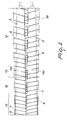
- the cage 2 accommodates internally at least one rotating screw feeder 5, which is provided with at least one helix 6 wound around a respective shaft 7; advantageously, the press 1 comprises an interspace 8 which is formed between a crest 6a of the helix 6 and an internal wall 2a of the cage 2, and positively the interspace 8 is thicker along at least one respective portion of the screw feeder 5, so as to facilitate the reverse flow and remixing of the material.
- the figures show a horizontal press 1 which comprises two screw feeders 5 with conical shafts 7; however, it is noted that the technical solutions described here can be applied equally to any type of vertical or horizontal press, single- or multiple-shaft presses, with draining shafts provided with perforated plates or with solid shafts.
- the screw feeders 5 are supported so that they can rotate at a respective end on respective supports 9 and are supported, at the opposite end, in a reduction unit 10, through which they are turned by a motor 11 which is mounted thereon.
- the filtration cage 2 is arranged around the screw feeders 5 and duplicates their profile.
- the internal wall 2a of the cage 2 is constituted by panels made of perforated metal plate, which allow the exit of the extracted liquid from the pressed material, which is constituted preferably but not exclusively by sugar beet pulp.
- Each screw feeder 5 comprises a respective shaft 7 which has a conical or cylindrical cross-section which tapers toward the outlet 4 of the material and at least one respective helix 6 which is wound onto the shaft 7. Further, the pitch of the helix 6 decreases from the inlet 3 toward the outlet 4, and the height of the helices 6 is such that the crest 6a of the helix 6 of one screw feeder 5 is tangent to the surface of the shaft 7 of the adjacent screw feeder 5.
- the material to be pressed introduced from the inlet 3, is drawn axially by the screw feeders 5 and in proceeding toward the outlet 4 the pressure of the material inside the press 1 increases, so as to perform its pressing.
- the pressed material is remixed, advantageously by way of the thicker interspace 8 which allows the reverse flow of the material inside the press.
- the thicker interspace 8 is formed at a first intermediate portion 12 of the screw feeder 5 or at an end portion 13 of the screw feeder 5, and in particular it is formed between the crest 6a of the helix 6, which is suitably shallower at said portions, and the internal wall 2a. Nonetheless, in further embodiments the helix 6 can be shallower at other portions of the screw feeder 5.
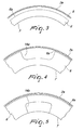
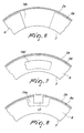
- the helix 6 can comprise at least one opening 14a, 14b, 14c, 14d at at least one of its portions, so as to allow the reverse flow and remixing of the material to be pressed and facilitate the expulsion of the liquid extracted from said material.
- the opening on a helix portion 6 is constituted by a contoured cutout 14a, which is open at the crest 6a of the helix 6.
- the opening is constituted by a window 14b, which is provided at the base of the helix 6 and opens onto the shaft 7 of the screw feeder 5.
- the opening is constituted by a discontinuity 14c of a portion of the helix 6, which is adapted to facilitate the remixing of the material.
- the opening is constituted by a slot 14d, which is located in an intermediate area of the helix 6 comprised between the crest 6a and the shaft 7.
- the press comprises a plurality of the openings 14a, 14b, 14c, 14d, which are preferably distributed at the first intermediate portion 12 of the screw feeder 5, which is formed substantially in a central region thereof (at intermediate pressing), or at the end portion 13 of the screw feeder 5 (when pressing is nearly completed).
- Both the thicker interspace 8 and the openings 14a, 14b, 14c, 14d allow the reverse flow of the material, which tends to retract partially, allowing its consequent remixing, thus allowing to cause the release of a greater amount of liquids from said material.
- the openings 14a, 14b, 14c, 14d affect only portions of the helix 6 whose extent is at the most approximately one third of a turn.
- the thicker interspace 8 which can affect the end portion 13 and/or the first intermediate portion 12 (or also other portions of the screw feeder 5), is formed by a shallower portion of the helix 6 for a larger total extension, provided on one or more pitches (which can be consecutive or not) of the helix 6.
- the increase in the thickness of the interspace 8 from the standard value to the maximum value can be gradual or sudden.
- first intermediate portion 12 of the screw feeder 5 which is adjacent to the first half 15 thereof and preferably but not exclusively has a length equal to approximately one tenth of the entire length of the shaft 7, a first remixing of the material occurs which is obtained by way of the shallower helix which forms the thicker interspace 8 or by way of the openings 14a, 14b, 14c, 14d: this facilitates the evacuation of water, especially from the more humid pulp parts, repositioning the less dehydrated material from the regions that lie furthest from the perforated metal plates 2a to the regions in contact with the perforated metal plates 2a of the cage 2, and vice versa.
- a second pressing of the material is performed until it is almost adjacent to the discharge outlet 4.
- the end portion 13 (whose length is preferably comprised between one fifth and one tenth of the length of the shaft 7), where the height of the helix 6 is lowest, a further remixing of the material is performed, and a simultaneous increase in pressure can be associated therewith in order to evacuate as much as possible the water that has remained inside it.
- a higher compression ratio the pitch of the helix 6 is reduced gradually with respect to the standard pitch
- Any increase in the compression ratio (reduction of the pitch of the helix 6) in the end portion 13 is gradual.
- the material dehydrated to an optimum level, exits from the discharge outlet 4;
- the extracted liquid such as the water extracted from the beet pulp, exits from the cage 2 through the lower port 4a or from the shafts, if they are of the draining type.
- the thicker interspace 8 and the openings 14a, 14b, 14c, 14d allow the reverse flow and remixing of the material during pressing, thus facilitating the exit of the liquid from the most disadvantaged regions (far from the perforated metal plates 2a of the cage 2).
- the press 1 can comprise a distribution of protrusions 17 which are associated with the internal wall 2a of the cage at the respective openings of the helix which open onto the crest thereof (and therefore at the cutouts 14a and at the discontinuities 14c): the protrusions 17 are adapted to engage in the respective openings 14a, 14c during the rotation of the screw feeders 5 and are advantageously flattened and arranged edgeways with respect to the advancement direction of the material, so as to facilitate its remixing and prevent its rotation about the shaft 7.
- the protrusions 17, by preventing the rotation of the material about the shaft 7, facilitate the advancement of the material, increasing the capacity of the press 1.
Landscapes
- Engineering & Computer Science (AREA)
- Mechanical Engineering (AREA)
- Filtration Of Liquid (AREA)
- Treatment Of Sludge (AREA)
- Addition Polymer Or Copolymer, Post-Treatments, Or Chemical Modifications (AREA)
Applications Claiming Priority (1)
| Application Number | Priority Date | Filing Date | Title |
|---|---|---|---|
| IT000344A ITBO20070344A1 (it) | 2007-05-10 | 2007-05-10 | Pressa per disidratazione meccanica |
Publications (2)
| Publication Number | Publication Date |
|---|---|
| EP1990180A2 true EP1990180A2 (fr) | 2008-11-12 |
| EP1990180A3 EP1990180A3 (fr) | 2009-10-21 |
Family
ID=39535480
Family Applications (1)
| Application Number | Title | Priority Date | Filing Date |
|---|---|---|---|
| EP08155758A Ceased EP1990180A3 (fr) | 2007-05-10 | 2008-05-07 | Presse pour déshydratation mécanique |
Country Status (2)
| Country | Link |
|---|---|
| EP (1) | EP1990180A3 (fr) |
| IT (1) | ITBO20070344A1 (fr) |
Cited By (1)
| Publication number | Priority date | Publication date | Assignee | Title |
|---|---|---|---|---|
| WO2024228105A1 (fr) * | 2023-05-02 | 2024-11-07 | Babbini S.P.A. | Machine fonctionnelle |
Citations (2)
| Publication number | Priority date | Publication date | Assignee | Title |
|---|---|---|---|---|
| FR71183E (fr) | 1957-04-11 | 1959-10-13 | Filtre-presse à marche continue | |
| GB1498243A (en) * | 1975-07-26 | 1978-01-18 | Simon Rosedowns Ltd | Screw presses |
Family Cites Families (7)
| Publication number | Priority date | Publication date | Assignee | Title |
|---|---|---|---|---|
| FR864166A (fr) * | 1940-03-19 | 1941-04-21 | Presse filtrante pour marc de pommes ou autres matières | |
| FR2242230A1 (en) * | 1973-09-05 | 1975-03-28 | Speichim | Continuously operating screw or single spindle press - has screw with steps for processing heterogeneous material with high liquid content |
| DE8009328U1 (de) * | 1980-04-03 | 1984-03-01 | Dambach-Industrieanlagen Gmbh, 7560 Gaggenau | Vorrichtung zum entwaessern und verdichten von rechengut, muell o.dgl. |
| JPS6289599A (ja) * | 1985-10-15 | 1987-04-24 | Yukio Miyagi | 水分を含んだ泥状物の脱水方法および装置 |
| GB2230788B (en) * | 1989-04-18 | 1992-08-26 | Jung Boo Kim | Apparatus and method for manufacturing solid fuel |
| JP2004148342A (ja) * | 2002-10-30 | 2004-05-27 | Kubota Corp | スクリュープレス |
| JP4152179B2 (ja) * | 2002-12-06 | 2008-09-17 | 株式会社クボタ | スクリュープレスおよび脱水方法 |
-
2007
- 2007-05-10 IT IT000344A patent/ITBO20070344A1/it unknown
-
2008
- 2008-05-07 EP EP08155758A patent/EP1990180A3/fr not_active Ceased
Patent Citations (2)
| Publication number | Priority date | Publication date | Assignee | Title |
|---|---|---|---|---|
| FR71183E (fr) | 1957-04-11 | 1959-10-13 | Filtre-presse à marche continue | |
| GB1498243A (en) * | 1975-07-26 | 1978-01-18 | Simon Rosedowns Ltd | Screw presses |
Cited By (1)
| Publication number | Priority date | Publication date | Assignee | Title |
|---|---|---|---|---|
| WO2024228105A1 (fr) * | 2023-05-02 | 2024-11-07 | Babbini S.P.A. | Machine fonctionnelle |
Also Published As
| Publication number | Publication date |
|---|---|
| EP1990180A3 (fr) | 2009-10-21 |
| ITBO20070344A1 (it) | 2008-11-11 |
Similar Documents
| Publication | Publication Date | Title |
|---|---|---|
| US5743178A (en) | Screw press for dehydrating fibrous materials | |
| EP1990181A2 (fr) | Presse pour déshydratation mécanique | |
| US6550376B2 (en) | Twin screw press with interrupted flights | |
| AU2006200347A1 (en) | Compression Screw with Combination Single and Double Flights | |
| EP2590812B1 (fr) | Installation de séparation à vis d'archimède pour traitement de suspension | |
| US7461591B2 (en) | Screw press for squeezing out fibrous material | |
| KR102025270B1 (ko) | 스크류 프레스 탈수장치 | |
| EP0930152A1 (fr) | Presse à vis pour la déshydratation de produits humides | |
| EP1990180A2 (fr) | Presse pour déshydratation mécanique | |
| WO2023130399A1 (fr) | Dispositif de pressage et procédé de séparation à utiliser pour l'extraction d'huile volatile de coque de mangoustan | |
| EP1663632B1 (fr) | Presse a vis pour comprimer de la matiere fibreuse, en particulier de la pulpe de betterave sucriere | |
| CN211650968U (zh) | 精制棉生产用挤压脱水装置 | |
| JPS60255300A (ja) | スクリユ−プレス型汚泥脱水機 | |
| JP5255696B2 (ja) | セルロースパルプを供給するための分配装置 | |
| WO2004080704A1 (fr) | Presse a vis comprenant une partie cylindrique | |
| US5855168A (en) | Sugar cane milling system | |
| NO146803B (no) | Anordning ved skruepresse | |
| CN206614824U (zh) | 用于植物秸秆脱水的螺旋挤压机 | |
| EP3228444B1 (fr) | Unité de compression servant à éliminer des liquides | |
| EP1066953A1 (fr) | Presse à alimentation par vis verticale pour la déshydratation de produits contenant du liquide | |
| WO2003031166A1 (fr) | Pressoir a vis, pressage de substance chargee de liquide, et mode d'utilisation | |
| AP685A (en) | Sugar cane milling system. | |
| CN117488572B (zh) | 一种精棉生产用挤浆机 | |
| KR0112450Y1 (ko) | 회전형 슬러지 탈수장치 | |
| CN209666365U (zh) | 一种无需辅助加热的螺旋式榨油机 |
Legal Events
| Date | Code | Title | Description |
|---|---|---|---|
| PUAI | Public reference made under article 153(3) epc to a published international application that has entered the european phase |
Free format text: ORIGINAL CODE: 0009012 |
|
| AK | Designated contracting states |
Kind code of ref document: A2 Designated state(s): AT BE BG CH CY CZ DE DK EE ES FI FR GB GR HR HU IE IS IT LI LT LU LV MC MT NL NO PL PT RO SE SI SK TR |
|
| AX | Request for extension of the european patent |
Extension state: AL BA MK RS |
|
| PUAL | Search report despatched |
Free format text: ORIGINAL CODE: 0009013 |
|
| AK | Designated contracting states |
Kind code of ref document: A3 Designated state(s): AT BE BG CH CY CZ DE DK EE ES FI FR GB GR HR HU IE IS IT LI LT LU LV MC MT NL NO PL PT RO SE SI SK TR |
|
| AX | Request for extension of the european patent |
Extension state: AL BA MK RS |
|
| 17P | Request for examination filed |
Effective date: 20100420 |
|
| AKX | Designation fees paid |
Designated state(s): AT BE BG CH CY CZ DE DK EE ES FI FR GB GR HR HU IE IS IT LI LT LU LV MC MT NL NO PL PT RO SE SI SK TR |
|
| 17Q | First examination report despatched |
Effective date: 20100615 |
|
| STAA | Information on the status of an ep patent application or granted ep patent |
Free format text: STATUS: THE APPLICATION HAS BEEN REFUSED |
|
| 18R | Application refused |
Effective date: 20111231 |