EP1990202A1 - Steuervorrichtung und Steuerverfahren für einenTintenstrahldrucker - Google Patents
Steuervorrichtung und Steuerverfahren für einenTintenstrahldrucker Download PDFInfo
- Publication number
- EP1990202A1 EP1990202A1 EP08290002A EP08290002A EP1990202A1 EP 1990202 A1 EP1990202 A1 EP 1990202A1 EP 08290002 A EP08290002 A EP 08290002A EP 08290002 A EP08290002 A EP 08290002A EP 1990202 A1 EP1990202 A1 EP 1990202A1
- Authority
- EP
- European Patent Office
- Prior art keywords
- ink
- deposition
- print medium
- printer
- ejection
- Prior art date
- Legal status (The legal status is an assumption and is not a legal conclusion. Google has not performed a legal analysis and makes no representation as to the accuracy of the status listed.)
- Granted
Links
- 238000000034 method Methods 0.000 title claims abstract description 22
- 230000008021 deposition Effects 0.000 claims abstract description 149
- 230000007246 mechanism Effects 0.000 claims description 59
- 230000009471 action Effects 0.000 claims description 11
- 230000008569 process Effects 0.000 description 16
- 230000003287 optical effect Effects 0.000 description 13
- 238000012360 testing method Methods 0.000 description 11
- 238000003491 array Methods 0.000 description 6
- 238000009826 distribution Methods 0.000 description 6
- 230000008878 coupling Effects 0.000 description 5
- 238000010168 coupling process Methods 0.000 description 5
- 238000005859 coupling reaction Methods 0.000 description 5
- 230000003247 decreasing effect Effects 0.000 description 5
- 230000006870 function Effects 0.000 description 5
- 239000003086 colorant Substances 0.000 description 3
- 238000001514 detection method Methods 0.000 description 3
- 238000012935 Averaging Methods 0.000 description 2
- 230000006837 decompression Effects 0.000 description 2
- 238000010586 diagram Methods 0.000 description 2
- 239000007788 liquid Substances 0.000 description 2
- 238000004519 manufacturing process Methods 0.000 description 2
- 238000004804 winding Methods 0.000 description 2
- 230000000712 assembly Effects 0.000 description 1
- 238000000429 assembly Methods 0.000 description 1
- 238000012790 confirmation Methods 0.000 description 1
- 238000001816 cooling Methods 0.000 description 1
- 230000010485 coping Effects 0.000 description 1
- 238000005520 cutting process Methods 0.000 description 1
- 230000000694 effects Effects 0.000 description 1
- 238000011156 evaluation Methods 0.000 description 1
- 238000010438 heat treatment Methods 0.000 description 1
- 239000011859 microparticle Substances 0.000 description 1
- 238000005457 optimization Methods 0.000 description 1
- 239000004800 polyvinyl chloride Substances 0.000 description 1
- 238000003860 storage Methods 0.000 description 1
Images


Classifications
-
- B—PERFORMING OPERATIONS; TRANSPORTING
- B41—PRINTING; LINING MACHINES; TYPEWRITERS; STAMPS
- B41J—TYPEWRITERS; SELECTIVE PRINTING MECHANISMS, i.e. MECHANISMS PRINTING OTHERWISE THAN FROM A FORME; CORRECTION OF TYPOGRAPHICAL ERRORS
- B41J2/00—Typewriters or selective printing mechanisms characterised by the printing or marking process for which they are designed
- B41J2/005—Typewriters or selective printing mechanisms characterised by the printing or marking process for which they are designed characterised by bringing liquid or particles selectively into contact with a printing material
- B41J2/01—Ink jet
- B41J2/21—Ink jet for multi-colour printing
- B41J2/2132—Print quality control characterised by dot disposition, e.g. for reducing white stripes or banding
- B41J2/2139—Compensation for malfunctioning nozzles creating dot place or dot size errors
-
- B—PERFORMING OPERATIONS; TRANSPORTING
- B41—PRINTING; LINING MACHINES; TYPEWRITERS; STAMPS
- B41J—TYPEWRITERS; SELECTIVE PRINTING MECHANISMS, i.e. MECHANISMS PRINTING OTHERWISE THAN FROM A FORME; CORRECTION OF TYPOGRAPHICAL ERRORS
- B41J2/00—Typewriters or selective printing mechanisms characterised by the printing or marking process for which they are designed
- B41J2/005—Typewriters or selective printing mechanisms characterised by the printing or marking process for which they are designed characterised by bringing liquid or particles selectively into contact with a printing material
- B41J2/01—Ink jet
- B41J2/07—Ink jet characterised by jet control
-
- B—PERFORMING OPERATIONS; TRANSPORTING
- B41—PRINTING; LINING MACHINES; TYPEWRITERS; STAMPS
- B41J—TYPEWRITERS; SELECTIVE PRINTING MECHANISMS, i.e. MECHANISMS PRINTING OTHERWISE THAN FROM A FORME; CORRECTION OF TYPOGRAPHICAL ERRORS
- B41J2/00—Typewriters or selective printing mechanisms characterised by the printing or marking process for which they are designed
- B41J2/005—Typewriters or selective printing mechanisms characterised by the printing or marking process for which they are designed characterised by bringing liquid or particles selectively into contact with a printing material
- B41J2/01—Ink jet
- B41J2/21—Ink jet for multi-colour printing
- B41J2/2121—Ink jet for multi-colour printing characterised by dot size, e.g. combinations of printed dots of different diameter
- B41J2/2128—Ink jet for multi-colour printing characterised by dot size, e.g. combinations of printed dots of different diameter by means of energy modulation
-
- B—PERFORMING OPERATIONS; TRANSPORTING
- B41—PRINTING; LINING MACHINES; TYPEWRITERS; STAMPS
- B41J—TYPEWRITERS; SELECTIVE PRINTING MECHANISMS, i.e. MECHANISMS PRINTING OTHERWISE THAN FROM A FORME; CORRECTION OF TYPOGRAPHICAL ERRORS
- B41J29/00—Details of, or accessories for, typewriters or selective printing mechanisms not otherwise provided for
- B41J29/38—Drives, motors, controls or automatic cut-off devices for the entire printing mechanism
Definitions
- the present invention relates to an inkjet printer comprising a plurality of printer heads each having a plurality of nozzles and a carriage holding the printer heads aligned in the anteroposterior direction, and conducting a predetermined printing on a printing surface of a print medium by combining an action of ejecting ink from the nozzles by an ejection controller while moving the carriage in the lateral direction by a lateral moving mechanism with anteroposterior movement of the print medium by an anteroposterior moving mechanism.
- An inkjet printer is an apparatus for printing information such as characters, figures, patterns on a printing surface of a print medium by ejecting microparticles of ink from a printer head while moving the printer head in the anteroposterior direction and the lateral direction relative to the print medium.
- the printer head has a plurality of nozzles for ejecting ink which are aligned in the anteroposterior direction at a predetermined pitch. While the ink ejection from the respective nozzles is controlled by an ejection controller, ink is ejected from the nozzles with moving a carriage in a lateral direction by a lateral moving mechanism so as to form a band-like deposition area of which width, i.e.
- print width corresponds to the width in the anteroposterior direction of the nozzle array from a nozzle at the front end to a nozzle at the rear end of the printer head and which extends in the lateral direction. This action is carried out in combination with the relative movement in the anteroposterior direction of the print medium by the anteroposterior moving mechanism, thereby printing desired information on the printing surface.
- a multi-head inkjet printer having a plurality of printer heads as mentioned above which are aligned in the anteroposterior direction in a carriage become popular.
- a multi-head inkjet printer having four printer heads which are shifted from each other in the anteroposterior direction and the lateral direction so that they are arranged in a zigzag shape so-called "staggered arrangement”
- respective nozzle arrays of the four printer heads are configured to be continued in the anteroposterior direction as seen from the side of the carriage so that the printer can print at once four times as wide as a print width of a single printer head from a nozzle at the front end of a printer head held at the front side of the carriage to a nozzle at the rear end of a printer head held at the rear side of the carriage (for example, see JP-A-2000-62153 ).
- printer heads having the same nozzle diameter and array are employed for the multi-head inkjet printer.
- an ejection controller for controlling the ink ejection of the respective printer heads outputs basically the same control signals as ejection control values to the respective heads.
- the ejection characteristics of the respective printer heads are actually slightly different from each other within a predetermined range even after setting predetermined parameters for each head unit so that the uniform color density over the entire print width may not be obtained even when the plurality of printer heads are controlled with ejection signal values for the uniform color density.
- the banding is not preferable because it affects the print quality. If this phenomenon is observed, it is necessary to replace each printer head held by the carriage and then start over the adjustment setting. Accordingly, there are problems of leading to more complexity of production process and taking longer time for the production. There is a possibility that one or more of printer heads is broken or damaged and is thus required to be replaced after delivering an inkjet printer. As the aforementioned phenomenon occurs under the circumstances, there is a problem of decreasing the operation rate of the inkjet printer.
- the present invention is made to address the aforementioned problems and it is an object of the present invention to provide a control device and a control method for an inkjet printer to ensure uniform color density over entire print width by all of a plurality of printer heads without complex operation such as replacing a printer head even when there is a variation in ejection characteristics of the respective printer heads.
- the invention according to claim 1 relates to a control device for an inkjet printer, the inkjet printer comprising: a carriage holding a plurality of printer heads which are aligned in the anteroposterior direction and each of which has a plurality of nozzles for ejecting ink; a medium holding means (for example, a platen 20 in the embodiment) for holding a print medium; a lateral moving mechanism (for example, a carriage moving mechanism 50 in the embodiment) for moving the carriage in the lateral direction along a printing surface of the print medium held by the medium holding means; an anteroposterior moving mechanism (for example, a medium moving mechanism 30 in the embodiment) for moving the print medium in the anteroposterior direction relative to the carriage; and an ejection controller (for example, an ejection control block 120 of a control device in the embodiment) for controlling ink ejection from the respective nozzles of the plurality of printer heads, wherein a predetermined printing is conducted on the printing surface of
- the control device for the inkjet printer comprises: a detecting means (for example, a deposition detecting unit 80 in the embodiment) for detecting the deposition states of ink deposited on the print medium; a comparing means (for example, a comparing section 122 in the embodiment) for comparing the deposition states detected by the detecting means; and a compensating means (for example, a compensating section 123 in the embodiment) for compensating the ejection control value of the ejection controller based on the comparison result of the comparing means, wherein the ejection controller activates the plurality of printer heads to eject ink according to ejection control values for uniform density to form a plurality of head correspondence deposition areas, corresponding to the respective printer heads, on the print medium, the detecting means detects a deposition state of ink in each head correspondence deposition area, the comparing means compares the deposition states of the plurality of head correspondence deposition areas, and based on the comparison result of the comparing means, the compensating means sets a compensation value for
- the "deposition state of ink” of the present invention means a geometric distribution state of ink deposited on the print medium, for example, the diameter (spot diameter) or the area of ink drop deposited on the print medium, the area density (the area of ink occupying a unit area) of ink in the deposition area, or the brightness of the deposition area.
- a temperature compensation value based on the temperature of the printer head is preferably used.
- the temperature compensation value based on the temperature of the printer head is a compensation value for coping with variation in ink drop diameter according to the variation in ambient temperature so as to make ink drops of constant ejection control value uniform. That is, as the ambient temperature of the printer head varies, the diameter of ink drop ejected from the nozzle varies relative to the same ejection control value due to variation in ink viscosity, the nozzle diameter, and the like.
- the variation of diameter of ink drop directly influences the deposition state of ink so that the density of entire print matter differs between summer, that is, higher temperature and winter, that is, lower temperature.
- inkjet printer has temperature compensation values for changing the diameter of ink drop to absorb the variation in diameter of ink drop according to the variation in ambient temperature.
- the aforementioned temperature compensation values are used to be adapted to one or some of printer heads as an object to be compensated. Relations between the ambient temperature and the diameter of ink drop ejected from nozzle are previously verified by means of tests or the like and are set and stored in a memory of the ejection controller.
- the deposition state of ink is preferably the diameter of ink drop deposited on the print medium and also preferably the area density of ink relative to the print medium.
- the invention according to claim 5 is a control method for an inkjet printer, the inkjet printer comprising: a carriage holding a plurality of printer heads which are aligned in the anteroposterior direction and each of which has a plurality of nozzles for ejecting ink; a medium holding means (for example, a platen 20 in the embodiment) for holding a print medium; a lateral moving mechanism (for example, a carriage moving mechanism 50 in the embodiment) for moving the carriage in the lateral direction along a printing surface of the print medium held by the medium holding means; an anteroposterior moving mechanism (for example, a medium moving mechanism 30 in the embodiment) for moving the print medium in the anteroposterior direction relative to the carriage; and an ejection controller (for example, an ejection control block 120 of a control device in the embodiment) for controlling ink ejection from the respective nozzles of the plurality of printer heads, wherein a predetermined printing is conducted on the printing surface of said print
- a medium holding means
- the control method comprises steps of: ejecting ink according to ejection control values for uniform density from the plurality of printer heads to form a plurality of head correspondence deposition areas; detecting a deposition state of ink in each head correspondence deposition area by a detecting means (for example, a deposition detecting unit 80 in the embodiment) for detecting the deposition states of ink deposited on the print medium; comparing the deposition states of the plurality of head correspondence deposition areas by a comparing means (for example, a comparing section 122 of the embodiment) for comparing the deposition states of ink detected the detecting means; and setting a compensation value for the ejection control value by a compensating means (for example, a compensating section 123 of the embodiment) to make the deposition states by the plurality of printer heads uniform.
- a detecting means for example, a deposition detecting unit 80 in the embodiment
- the invention according to claim 1 is a control device for an inkjet printer of a multi-head type as described above.
- the plurality of printer heads are activated to eject ink according to ejection control values for uniform density to form band-like head correspondence deposition areas corresponding to the printer heads, respectively.
- the detecting means detects the deposition states of ink in the respective head correspondence deposition areas and the comparing means compares the deposition states of ink in the head correspondence deposition areas. Based on the comparison result, a compensation value for the ejection control value is set to make the deposition states by the plurality of printer heads uniform.
- a test print is conducted with ejection control values for making uniform color density over entire print width originally, the deposition states of ink in respective head correspondence deposition areas are detected and compared, and a compensation value relative to the ejection control value is automatically set to make the deposition states of ink by the printer heads uniform.
- the control device of the present invention therefore, there is provided a multi-head inkjet printer having a plurality of printer heads which can print with uniform color density over entire print width without complex operation such as replacing a printer head because a compensation value relative to the ejection control value is set for an appropriate printer head even when banding would occur due to a variation in ejection characteristics of the printer heads under conventional circumstances.
- an existing temperature compensation value is adapted to a printer head as the object to be compensated, thereby changing and compensating the diameters of ink drops ejected from nozzles to make the deposition state of ink of the respective head correspondence deposition areas uniform and thus preventing occurrence of banding by a simple and reasonable system.
- the diameter (spot diameter) of deposited ink formed by ink drop is used as the detection value, thereby ensuring steady compensation by a simple control system.
- the relation between the diameter of ink drop changed by the temperature compensation values and the spot diameter is a linear relation so that the process is simple, that is, the compensation can be quickly and surely achieved without conducting the test print several times.
- the area density of ink relative to said print medium as the deposition state of ink suitable comparison with little error is ensured even when there are ink dots of which shapes are deformed circles.
- the area of ink occupying a constant area, that is, the density of a deposition area is used as the detection value, thereby easily setting a compensation value capable of compensating the difference in density close to that observed by eyes.
- the invention according to claim 5 is a control method for a multi-head inkjet printer.
- the plurality of printer heads are activated to eject ink according to ejection control values for uniform density to form band-like head correspondence deposition areas corresponding to the printer heads, respectively.
- the detecting means detects the deposition states of ink in the respective head correspondence deposition areas and the comparing means compares the deposition states of ink in the head correspondence deposition areas detected by the detecting means.
- the compensating means sets a compensation value for the ejection control value to make the deposition states by the plurality of printer heads uniform.
- a test print is conducted with ejection control values for making uniform color density over entire print width originally, the deposition states of ink in respective head correspondence deposition areas are detected by the detecting means and are compared by the comparing means, and a compensation value relative to the ejection control value is set by the compensating means to make the deposition states of ink by the printer heads uniform. Therefore, in a multi-head inkjet printer having a plurality of printer heads, the control method enables the printer to print with uniform color density over entire print width without complex operation such as replacing a printer head because a compensation value relative to the ejection control value is set for an appropriate printer head even when banding would occur due to a variation in ejection characteristics of the printer heads under the conventional control method.
- a control device and a control method for an inkjet printer capable of printing with uniform color density over entire print width by all of a plurality of printer heads without complex operation even when there is a variation in ejection characteristics of the respective printer heads.
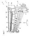
- Fig. 2 is a perspective view showing, as an example of inkjet printer (hereinafter, referred to as "printing apparatus") to which the present invention is applied, a printing apparatus P of a type having X-Y axes, i.e. two axes one of which is for movement of a print medium and the other one of which is for movement of a printer head, taken diagonally from the front.
- Fig. 3 shows a schematic structure of a main unit of the printing apparatus P. First, the schematic structure of the printing apparatus P will be described with reference to these drawings. It should be noted that the directions of arrows F, R, U marked in Fig. 2 are forward, rightward, upward in the following description, respectively.
- the printing apparatus P is an apparatus for conducting a predetermined action such as printing to a sheet-like print medium M called "medium” such as a tarpaulin and a weather-resistant polyvinyl chloride (PVC) sheet and mainly comprises a main unit 1 having a shape like a horizontally long rectangular box and a supporting unit 2 for supporting the main unit 1 at a position facilitating the operation. Disposed before and behind right and left legs 2a as components of the supporting unit 2 are a feeding mechanism 3 for feeding a unprocessed print medium which is rolled up and a winding mechanism 4 for winding up the print medium after printing.
- medium such as a tarpaulin and a weather-resistant polyvinyl chloride (PVC) sheet
- PVC polyvinyl chloride
- the main unit 1 comprises a body 10 as a base for mounting respective mechanisms, a platen 20 for supporting a print medium M, a medium moving mechanism 30 for moving the print medium M supported by the platen 20 forward and backward, carriage 40 which is supported above the platen 20 movably rightward and leftward along the upper surface of the print medium M and holds a plurality of printer heads at predetermined gaps, a carriage moving mechanism 50 for moving the carriage rightward and leftward relative to the print medium M supported by the platen 20, and a control device 100 which includes an ejection control block for controlling ink ejection from respective nozzles of the printer heads and controls actions of respective parts of the printing apparatus P.
- the body 10 comprises a body frame 11 composed of a lower frame 11L in which the platen 20, feeding rollers of the medium moving mechanism 30, and the like are disposed and an upper frame 11U in which pinch rollers of the medium moving mechanism 30 and a supporting structure for the carriage 40 are disposed.
- a medium passage 15 like a horizontally long window through which the print medium M can pass and move forward and backward.
- the body 10 is surrounded by a front cover 13a covering the central portion of the body frame 11 and side covers 13b covering the right and left sides of the body frame 11 and is thus configured to have a shape like a horizontally long rectangular box as a whole.
- the platen 20 is disposed at a central portion of the body 10 to extend over the anteroposterior length of the medium passage 15 and is provided on its upper surface with a supporting surface 21 for horizontally supporting the print medium M.
- the supporting surface 21 is provided with a number of suction holes formed therein.
- a decompression chamber is disposed which can be set to have a negative pressure. By setting the decompression chamber to have a negative pressure, the print medium M is held on the supporting surface 21 by means of suction during the printing process and the cutting process.
- the front end and the rear end of the platen 20 extend downwards through smooth curved surfaces.
- a heater for heating the print medium to dry ink just after printed is disposed.
- the medium moving mechanism 30 comprises a cylindrical feed roller 31 which is supported by the lower frame 11L positioned at a front lower portion below the medium passage 15 such that the cylindrical roller is rotatable about a rotation axis extending in the lateral direction and of which upper surface is exposed to the supporting surface 21 of the platen, a plurality of roller assemblies 35, each having rotatable pinch rollers 36 aligned in the anteroposterior direction, which are aligned at predetermined intervals in the lateral direction on the upper frame 11U above the feed roller 31, and a roller driving mechanism 32 which has an electric motor 32m for driving the feed rollers 31 to rotate and of which operation is controlled by the control device 100.
- the roller assembly 35 has a clamp position in which the pinch rollers 36 are pressed against the feed roller 31 to catch the print medium M between the upper and lower rollers 31 and 36 and an unclamp position in which the pinch rollers 36 are spaced apart upward from the feed roller 31 to allow free movement of the print medium M on the platen 20.
- the roller assembly 35 can be displaced between the clamp position and the unclamp position.
- the roller assembly 35 When the roller assembly 35 is set to the clamp position so as to press the pinch rollers 36 against the feed roller 31 from above through the print medium M on the platen, the print medium M is held in the clamped state, that is, caught between the upper and lower rollers.
- the feed roller 31 As the feed roller 31 is rotated by the roller driving mechanism 32 in this clamped state, the print medium M pressed against the feed roller 31 is moved in the anteroposterior direction for a feed rate corresponding to the rotating angle of the feed roller 31, that is, a feed rate according to a drive control value outputted from the control device 100 to the roller driving mechanism 32.
- a guide rail 45 extending in the lateral direction parallel to the feed roller 31.
- the carriage 40 having a plurality of printer heads is supported by the guide rail 45 such that the carriage 40 is movable in the lateral direction.
- the guide rail 45 is a supporting rail of a linear motion bearing such as a linear guide.
- the carriage 40 is fixed to a slide block (sometimes called ball housing or the like) fitted and supported by the guide rail 45, whereby the carriage 40 is supported above the platen 20 slidably in the lateral direction and is moved by a carriage moving mechanism 50 in the lateral direction as will be described later.
- the carriage moving mechanism 50 comprises a driving pulley 51 and a driven pulley 52 which are located near the opposite ends in the lateral direction of the guide rail 45, respectively, an electric motor 53 for driving the driving pulley 51 to rotate, and an endless driving belt 55 which is spanned between the driving pulley 51 and the driven pulley 52.
- the carriage 40 is connected and fixed to the driving belt 55.
- the electric motor 53 may be a servomotor or a stepping motor
- the driving belt 55 may be a timing belt having a number of teeth formed in its inner periphery
- the driving and driven pulleys 51, 52 may be timing belt pulleys.
- the carriage 40 is adapted to be finely controlled its movement (the direction of movement, the speed of movement, the position in the lateral direction).
- the plurality of printer heads 60 for ejecting ink are aligned.
- the arrangement of the printer heads 60 as seen from the bottom of the carriage 40 is shown in Fig. 4 .
- the printing apparatus P is configured to be a multi-head structure of a staggered arrangement in which, as shown in Fig. 4 , four printer heads 60 each including a number of nozzles and capable of ejecting fine ink drops are shifted from each other in the anteroposterior direction and the lateral direction so that they are arranged in a zigzag shape.
- Each printer head 60 is composed of a plurality of nozzle arrays 61 which are aligned in the lateral direction.
- Each nozzle array 61 is formed by a plurality of nozzles 62 for ejecting fine ink drops which are aligned linearly in the anteroposterior direction.
- Each nozzle array 61 is an array of nozzles which are connected to a common liquid path for supplying ink to respective nozzles 62 linearly aligned so as to eject ink of the same color.
- the respective nozzle arrays are set to eject ink of respective colors.
- the printer head 60 of this embodiment has a structure having eight nozzle arrays 61 which are aligned in the lateral direction in parallel to each other and each of which is composed of one hundred eighty nozzles 62.
- the printer head 60 is configured such that each two of the nozzle arrays 61 are for one of colors, i.e. black (B), cyan (C), magenta (M), and yellow (Y).
- the printer heads 60, 60 ... are disposed on the lower surface of the carriage 40 facing the supporting surface 21 of the platen such that the printer heads 60, 60 ... are level with each other to have the same distance (gap) from the supporting surface 21 and the anteroposterior ends of the nozzle arrays of the four printer heads 60 are located continuously as seen from a lateral side of the carriage 40.
- the four printer heads 60, 60 ... are marked with A, B, C, D in the order of from the front printer head for convenience of explanation.
- the distance in the anteroposterior direction between the nozzles at the rear end position of the front-side printer head 60A and the nozzles at the front end position of the rear-side printer head 60B is set to be equal to the pitch between adjacent nozzles 62 and 62 in the same nozzle array 61.
- each printer head 60A, 60B, 60C, 60D forms a band-like head correspondence deposition area of an anteroposterior width w of each nozzle array 61 so that the four printer heads as a whole form an integral deposition area without empty space of a print width W (four times as wide as the print width w of the single printer head 60) from the nozzles at the front end position of the printer head 60A held at the front end side of the carriage 40 to the nozzles at the rear end position of the printer head 60D held at the rear end side of the carriage 40.
- each printer head 60 a common liquid path for each nozzle array 61 is connected through a tube to an ink storage portion of a cartridge type which is disposed on the body 10 side so as to supply ink to the nozzle array 60 and an actuator for ejecting ink such as a piezoelectric element disposed in a pressure chamber of each nozzle is connected to the control device 100 through a signal line, whereby the ejection of the ink from the printer head 60 is controlled.
- the control device 100 is adapted to control the operations of the medium moving mechanism 30, the carriage moving mechanism 50, and the printer heads 60 according to a control program which is previously set in the printing apparatus P and a process program which is read according to an object to be processed.
- control device 100 controls the medium moving mechanism 30 to move the print medium M to a predetermined reference position and hold the print medium M on the supporting surface 21 by means of suction and controls the respective nozzles of the four printer heads 60 to eject ink drops of color(s) and of diameter(s) according to the process program in positions in the lateral direction according to the process program while controlling the carriage moving mechanism 50 to move the carriage 40 in the lateral direction, thereby forming a laterally long band-like ink deposition area of the print width W.
- This action is carried out in combination with and alternately with the movement in the anteroposterior direction of the print medium M by the medium moving mechanism 30, thereby producing predetermined information such as characters, figures, images according to the process program on the printing surface of the print medium M.
- ink drops are ejected from the respective nozzles 62, 62, ... of the four printer heads 60A through 60D while moving the carriage 40 in the lateral direction (one way or reciprocation) so as to form an ink deposition area of the print width W at once.
- four printer heads 60 of the same specification are used as the printer heads 60A through 60D. Basically, when the printer heads 60A through 60D are actuated with control signal values for the same density (equal drop diameters), the densities of the respective head correspondence deposition areas formed with ink from the printer heads are uniform, thereby achieving uniform density in the ink deposition area of the print width W.
- the ink ejection characteristics of the printer heads 60 may vary within a certain range because of their predetermined tolerance.
- the ink ejection characteristics may vary slightly due to temperature distribution in the carriage to which the printer heads are mounted, differences in flow resistance in a piping system for supplying ink to the printer heads, and differences in electrical characteristics in a signal transmitting system for transmitting driving signals to the ejection actuators of the printer heads.
- the density of the head correspondence deposition area printed by any printer head may be lower (or higher) than that of the other head correspondence deposition areas, thus producing a strap like contrasting density (banding) in the ink deposition area of the print width W.
- the printing apparatus P has an inter-head ejection characteristic adjusting function for compensating differences in the ejection characteristics among the printer heads in order to finally achieve uniform density of the head correspondence deposition areas, that is, to prevent banding even when there is variation in characteristics of the printer heads 60A through 60D.
- the control device 100 is adapted to control the actions of the respective parts.
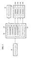
- Fig. 1 is a block diagram showing the control structure for achieving the inter-head ejection characteristic adjusting function.
- the control structure comprises mainly a deposition detecting unit 80 for detecting deposition states of ink deposited on the print medium M, a movement control block 110 disposed in the control device 100 for controlling the drive of the medium moving mechanism and the carriage moving mechanism and an ejection control block 120 disposed in the control device 100 for controlling the ejection of ink from the respective printer heads, the carriage moving mechanism 50 for moving the carriage 40 based on command signal outputted from the control device 100, and the printer heads 60A through 60D.
- the ejection control block 120 in the control device comprises a calculation section 121, a comparing section 122 for comparing the deposition states detected by the deposition detecting unit 80, a compensating section 123 for compensating the ejection control values for the respective printer heads, and an actuator driving section 125 for outputting driving signals to the actuators of the respective printer heads.
- the deposition detecting unit 80 is a unit for detecting the deposition states of ink deposited on the print medium M and comprises an observation optical system 81 for observing the deposition area of ink, and a photographing optical system 82 for taking an image of the deposition area observed by the observation optical system 81.
- the observation optical system 81 may be, for example, a lens system for optically magnifying the ink deposition area by ten times through twenty times.
- the photographing optical system 82 may be a color or monochrome CCD camera. Image of the ink deposition area taken by the photographing optical system is converted into an image signal. The image signal is outputted from the deposition detecting unit 80 and inputted into the control device 100.
- the deposition detecting unit 80 is supported by the guide rail 45 so that the deposition detecting unit 80 can slide in the lateral direction above the print medium M and is adapted to be engaged with a hook receiving portion of a holding station disposed on a left side outside of the printing area and with a hook receiving portion disposed on a left wall of the carriage 40 by a coupling mechanism 85 of swinging hook form disposed in the deposition detecting unit 80. Accordingly, the carriage 40 is moved by the carriage moving mechanism 50 to a position in the vicinity of the left end of the guide rail 45, the deposition detecting unit 80 is then coupled with the carriage 40 by the coupling mechanism 85, and the coupling between the holding station and the deposition detecting unit 80 is cancelled.
- the deposition detecting unit 80 By moving the carriage 40 in this state to the right, the deposition detecting unit 80 is moved to any place in the lateral direction on the print medium M so as to observe the print medium M.
- the deposition detecting unit 80 is also adapted to hold the observation optical system 81 and the photographing optical system 82 such that they are movable in the anteroposterior direction relative to the print medium M.
- the deposition detecting unit 80 can observe the head correspondence deposition areas formed by the respective printer heads 60A through 60D.
- the ejection control block 120 conducts a control of outputting ejection control signals of ejection control values according to the process program to the respective actuators provided corresponding to the respective nozzles 62, 62 ... of the printer heads 60A through 60D according to the process program read by the control device 100 so as to eject ink drops of a diameter corresponding to the ejection control value at a predetermined position in the lateral direction of the print medium M. That is, the density of information such as an image to be printed on the print medium M by the printing apparatus P is defined by the drop diameter of the ink drops ejected from the respective nozzles 62 to deposit on the print medium M and the distribution density in the lateral direction.
- Fig. 5 is a schematic illustration showing a state that the density of a head correspondence deposition area A B , as the second raw from the front F (the lower side in Fig. 5 ), formed by the printer head 60B is lower than the density of the head correspondence deposition areas A A , A C , A D formed by the other printer heads 60A, 60B, 60C even when the printer heads 60A through 60D are controlled to eject ink with ejection control values of the same density to form an ink deposition area of the print width W.
- Enlarged images of the head correspondence deposition areas A B and A C detected by the deposition detecting unit 80 are schematically shown in circles.
- the calculation section 121 of the ejection control block 120 calculates the deposition states of ink deposited on the print medium M from image signals, as shown in Fig. 5 , inputted from the deposition detecting unit 80.
- the deposition states of ink that is, the geometric distribution state of ink deposited on the print medium M can be evaluated by various evaluation methods according to, for example, the spot diameters or areas of deposited ink drops, the density per area of ink, and the lightness of an area to be observed. The following description will be made with regard to a case using the spot diameters, that is, diameters of ink dots deposited and formed on the print medium, as the deposition states of ink.
- the calculation section 121 calculates the spot diameters ⁇ D A through ⁇ D D of ink in the respective head correspondence deposition areas A A through A D based on image signals inputted from the deposition detecting unit 80.
- the spot diameter for each head correspondence deposition area is obtained by calculating spot diameters of a plurality of dots and averaging the calculated spot diameters.
- the comparing section 122 compares the spot diameters ⁇ D A through ⁇ D D of the respective head correspondence deposition areas obtained by the calculation section 121.
- the comparing method may be a known method, for example, difference ( ⁇ D B - ⁇ D), percentage ( ⁇ D B / ⁇ D), or ratio (( ⁇ D B - ⁇ D) / ⁇ D) of the spot diameter of each head correspondence deposition area relative to the average ⁇ D of the spot diameters ⁇ D A through ⁇ D Do
- the compensating section 123 sets a compensation value to the ejection control value based on the aforementioned comparison result.
- employed as the compensation value is a temperature compensation value which is previously set to cope with variation in ink drop diameter according to the variation in ambient temperature.
- the temperature compensation value is a compensation value for increasing or decreasing the amplitude of ejection control signal to be outputted to the actuators of the nozzles within a certain range. For example, since the higher the ambient temperature is, the lower the dynamic coefficient of viscosity of the ink is (the easier the ink flows), the diameter of ink drops ejected from the nozzles is increased. Therefore, a compensation value for decreasing the amplitude of ejection control signal is previously set and stored as a temperature compensation value for higher temperature.
- the actuator driving section 125 outputs an ejection control signal of an amplitude corresponding to the ejection control value of the process program to the actuators disposed to pressure chambers (generally, piezoelectric elements PZT are used) corresponding to the nozzles 62, 62 ... of the printer heads 60A through 60D so as to eject ink drops of diameters according to the ejection control signals from the respective nozzles 62, 62 ... to the print medium M.
- the actuator driving section 125 outputs an ejection control signal to which the temperature compensation value is applied to the ejection control value to the actuators of the respective nozzles of the appropriate printer head(s).
- Figs. 6(a)-6(c) are explanatory illustrations showing aspects of the spot diameter which varies according to the setting of the temperature compensation value. Illustrated in the upper side of this drawing are dots D C of the head correspondence deposition area A C formed by the printer head 60C shown in Fig. 5 and illustrated in the lower side are dots D B of the head correspondence deposition area A B formed by the printer head 60B.
- D C of the head correspondence deposition area A C formed by the printer head 60C shown in Fig. 5
- dots D B of the head correspondence deposition area A B formed by the printer head 60B are explanatory illustrations showing aspects of the spot diameter which varies according to the setting of the temperature compensation value. Illustrated in the upper side of this drawing are dots D C of the head correspondence deposition area A C formed by the printer head 60C shown in Fig. 5 and illustrated in the lower side are dots D B of the head correspondence deposition area A B formed by the printer head 60B.
- (a) shows a state before setting a compensation value
- (b) shows
- the compensating section 123 selects a temperature compensation value only for the printer head 60B according to the result (difference, percentage, ratio or the like) of the comparison by the comparing section 122 to set the temperature compensation value to the ejection control value to the printer head 60B.
- the actuator driving section 125 outputs an ejection control signal, in which the temperature compensation value is adapted to the ejection control value, to the actuators of the respective nozzles of the printer head 60B.
- a temperature compensation value for lower temperature according to the comparison result is set. Accordingly, the diameter of ink dots ejected from the printer head 60B is increased so that the spot diameter of the dots D B by the printer head 60B is set to be equal to the spot diameter by the other printer heads 60A, 60C, 60D as shown in Fig. 6(c) .
- Figs. 7(a)-7(c) are explanatory illustrations showing aspects of the spot diameter which varies according to the setting of the temperature compensation value similar to Figs. 6(a)-6(c) . In this case, however, the difference between the spot diameter ⁇ D B of dots D B by the printer head 60B and the spot diameter ⁇ D C of dots D C by the printer head 60C is large.
- the compensating section 123 sets temperature compensation values not only for the printer head 60B but also for the other printer heads 60A, 60C, 60D according to the result (difference, percentage, ratio or the like) of the comparison by the comparing section 122 to set the temperature compensation values to the ejection control values to the respective printer heads.
- a temperature compensation value for lower temperature is set to increase the diameter of ink dots ejected from the printer head 60B and a temperature compensation value for higher temperature is set to decrease the diameter of ink dots ejected from the other printer heads. Accordingly, the diameter of ink dots ejected from the printer head 60B is increased while the diameter of ink dots ejected from the other printer heads is decreased so that the spot diameters of the dots by all of the printer heads are set to be equal to each other as shown in Fig. 7(c) .
- the inter-head ejection characteristic adjusting function is set and stored in the control device 100 as an inter-head ejection characteristic adjusting program for carrying out this function.
- the control device 100 carries out test printing for forming four head correspondence deposition areas corresponding to the printer heads 60A, 60B, 60C, 60D, respectively, to the print medium M. That is, the control device 100 outputs a driving control signal from the movement control block 110 to the medium moving mechanism 30 to move the print medium M to a predetermined reference position and hold the print medium M on the supporting surface 21 by means of suction, and output ejection control signals of an ejection control value for the same density from the ejection control block 120 to the printer heads 60A through 60D to eject ink from the nozzles 62, 62 ... of the respective printer heads while moving the carriage 40 in the lateral direction by the carriage moving mechanism 50, thereby forming an ink deposition area of the print width W composed of four head correspondence deposition areas.
- the control device 100 moves the carriage 40 to the left by the carriage moving mechanism 50 to couple the carriage 40 with the deposition detecting unit 80, which has been held by the holding station, by the coupling mechanism 85, and then moves the carriage 40 to the right to move the deposition detecting unit 80 to a predetermined position in the lateral direction, for example, a middle position of the print medium M. Then, the control device 100 moves the observation optical system 81 and the photographing optical system 82 of the deposition detecting unit 80 in the anteroposterior direction and controls the photographing optical system 82 to sequentially take enlarged images of the head correspondence deposition areas A A through A D produced by the printer heads 60A through 60D.
- Image signals of images taken by the photographing optical system 82 are inputted into the calculating section 121 of the ejection control block 120.
- the calculating section 121 processes the image signals inputted from the deposition detecting unit 80 to calculate the spot diameters D A through D D of ink in the respective head correspondence deposition areas A A through A D .
- the spot diameters D A through D D calculated are compared by the comparing section 122.
- the compensating section 123 sets and stores temperature comparison values according to the comparison results as shown in Fig. 6 and Fig. 7 .
- an ejection control signal in which a temperature compensation value is added to the ejection control value of each printer head according to the process program is outputted from the actuator driving section 125 to the appropriate printer head (60B), thereby controlling the spot diameters of the printer heads 60A through 60D to be equal in relation to the ejection control value for the uniform density.
- the spot diameters ⁇ D A through ⁇ D D and the distribution densities of ink in the head correspondence deposition areas A A through A D formed by the respective printer heads are uniform so as to make the density of the respective head correspondence deposition areas uniform, thereby enabling the entire print width W to be printed with uniform density.
- the control device 100 displays a message on the display panel of the control device 100 to ask the operator whether or not to start a test print for confirmation and waits for an answer. If there is a command to start the test print, the control device 100 outputs a driving control signal to the medium moving mechanism 30 to move the print medium for a predetermined amount forward and then conducts the test print again with the ejection control signals plus the temperature compensation value(s).
- the control device 100 outputs a driving control signal from the movement control block 110 to the carriage driving mechanism 50 to move the carriage 40 to the holding station at which the deposition detecting unit 80 is engaged with the holding station by the coupling mechanism 85 and the engagement between the carriage 40 and the deposition detecting unit 80 is canceled. Then, the carriage 40 is moved to a predetermined waiting position, for example, a waiting station on the right side of the medium passage 15 and is stopped in the waiting state. Thus, the inter-head ejection characteristic adjusting program is terminated.
- the optimization of temperature compensation value(s) may be conducted by detecting spot diameters at a plurality of position on both right and left sides for the ink deposition area of the print width W and comparing the spot diameters detected.
- the test print may be conducted by forming a plurality of rows of ink deposition areas with different brightness and different chromaticness and averaging the respective temperature compensation values for the brightness and chromaticness obtained by the test print, and may be conducted using different temperature compensation values for every ink rows which have different colors.
- a suitable compensation value is automatically set for an appropriate printer head as an object to be compensated, thereby ensuring printing with uniform density over entire print width W without complex operation such as replacing the printer head. Since existing temperature compensation values are used as the compensation values, a simple and reasonable arrangement for preventing the banding is achieved.
- an arrangement of detecting spot diameters of ink deposited on a print medium M is used, thereby achieving steady compensation with a relatively simple control system.
- the deposited area or the area density (the area of ink occupying a unit area of a print medium) of ink deposited on the print medium M is used as the indexical property for evaluating the ink deposition state
- accurate detection and comparison can be conducted so as to enable setting of a suitable temperature compensation value even when there are ink dots of which shapes are deformed circles (making its diameter hard to calculate (easily making large error in calculation) such as a gourd-like shape and a meteoric shape).
- the compensating section 123 calculates a compensation value based on the comparison result by the comparing section 122 and the ejection control signal is changed by using the compensation value may be employed.
- a control of increasing or cooling down the temperature of the appropriate printer head or the temperature of ink to be supplied to the appropriate printer head for a temperature corresponding to the temperature compensation value is conducted may be employed.
- the present invention may be adapted to an inkjet printer of another type, for example, a printing apparatus of a table moving type in which a print medium is fixed and held on a table and the table is moved and a printing apparatus of a head moving type in which a X-axis carriage and a Y-axis carriage are moved in both X-Y directions relative to a table holding a print medium.
Landscapes
- Engineering & Computer Science (AREA)
- Quality & Reliability (AREA)
- Ink Jet (AREA)
Applications Claiming Priority (1)
| Application Number | Priority Date | Filing Date | Title |
|---|---|---|---|
| JP2007124899A JP2008279640A (ja) | 2007-05-09 | 2007-05-09 | インクジェットプリンタの制御装置及び制御方法 |
Publications (2)
| Publication Number | Publication Date |
|---|---|
| EP1990202A1 true EP1990202A1 (de) | 2008-11-12 |
| EP1990202B1 EP1990202B1 (de) | 2011-10-26 |
Family
ID=39135231
Family Applications (1)
| Application Number | Title | Priority Date | Filing Date |
|---|---|---|---|
| EP08290002A Not-in-force EP1990202B1 (de) | 2007-05-09 | 2008-01-02 | Steuervorrichtung und Steuerverfahren für einenTintenstrahldrucker |
Country Status (6)
| Country | Link |
|---|---|
| US (1) | US8303068B2 (de) |
| EP (1) | EP1990202B1 (de) |
| JP (1) | JP2008279640A (de) |
| KR (1) | KR101390403B1 (de) |
| CN (1) | CN101301812A (de) |
| AT (1) | ATE530349T1 (de) |
Families Citing this family (11)
| Publication number | Priority date | Publication date | Assignee | Title |
|---|---|---|---|---|
| WO2012053674A1 (ko) * | 2010-10-20 | 2012-04-26 | 주식회사 씨드 | 3차원 광경화 잉크젯 프린팅 시스템 |
| JP5618839B2 (ja) * | 2011-01-04 | 2014-11-05 | 東芝テック株式会社 | インクジェット記録装置及び記録方法 |
| JP5472152B2 (ja) * | 2011-02-18 | 2014-04-16 | ブラザー工業株式会社 | 印刷制御装置及び印刷制御プログラム |
| CN102848737B (zh) * | 2011-06-27 | 2015-03-11 | 山东新北洋信息技术股份有限公司 | 打印机及打印控制方法 |
| US8414102B2 (en) | 2011-08-11 | 2013-04-09 | Xerox Corporation | In situ calibration of multiple printheads to reference ink targets |
| US8851601B2 (en) | 2012-02-07 | 2014-10-07 | Xerox Corporation | System and method for compensating for drift in multiple printheads in an inkjet printer |
| JP6245754B2 (ja) * | 2014-03-27 | 2017-12-13 | クオリカプス株式会社 | インクジェットマーキング装置および方法 |
| JP6251819B2 (ja) * | 2014-10-16 | 2017-12-20 | 株式会社小森コーポレーション | デジタル印刷機 |
| JP6769732B2 (ja) * | 2016-04-22 | 2020-10-14 | 東芝テック株式会社 | 補正データ設定装置及びインクジェットプリンタ |
| CN109476161B (zh) * | 2016-07-29 | 2021-01-08 | 惠普发展公司,有限责任合伙企业 | 打印设备、计算机可读介质和打印方法 |
| JP2023060754A (ja) * | 2021-10-18 | 2023-04-28 | 株式会社日立産機システム | インクジェット記録システム、印字情報補正方法 |
Citations (4)
| Publication number | Priority date | Publication date | Assignee | Title |
|---|---|---|---|---|
| EP0670219A2 (de) * | 1994-03-04 | 1995-09-06 | Canon Kabushiki Kaisha | Verfahren und Vorrichtung für Thermo-Farbstrahldrucken |
| JP2000062153A (ja) | 1998-08-24 | 2000-02-29 | Mimaki Engineering:Kk | インクジェットプロッタ |
| US20060132875A1 (en) * | 2004-12-16 | 2006-06-22 | Seiko Epson Corporation | Image processing device, image processing method, and program |
| WO2006089105A2 (en) * | 2005-02-18 | 2006-08-24 | Applied Materials, Inc. | Methods and apparatus for precision control of print head assemblies |
Family Cites Families (19)
| Publication number | Priority date | Publication date | Assignee | Title |
|---|---|---|---|---|
| US5276459A (en) * | 1990-04-27 | 1994-01-04 | Canon Kabushiki Kaisha | Recording apparatus for performing uniform density image recording utilizing plural types of recording heads |
| EP0461759B1 (de) * | 1990-05-11 | 1995-09-13 | Canon Kabushiki Kaisha | Aufzeichnungsgerät mit Aufzeichnungskopf |
| JP2950950B2 (ja) * | 1990-08-31 | 1999-09-20 | キヤノン株式会社 | 画像記録装置 |
| JP3253107B2 (ja) * | 1991-09-03 | 2002-02-04 | キヤノン株式会社 | インクジェット記録装置および記録方法 |
| JP3226642B2 (ja) * | 1992-12-28 | 2001-11-05 | キヤノン株式会社 | インクジェット記録装置およびインクジェット記録装置における濃度調整方法 |
| KR100198171B1 (en) * | 1994-03-04 | 1999-06-15 | Canon Kk | Printing head and printing apparatus and method using the same |
| JPH0911463A (ja) * | 1995-06-28 | 1997-01-14 | Fuji Xerox Co Ltd | インクジェット記録装置、インクジェット記録装置の駆動装置、インクジェット記録方法 |
| JPH10235905A (ja) * | 1997-02-26 | 1998-09-08 | Tec Corp | 画像形成装置の濃度補正方法 |
| JP3554184B2 (ja) * | 1997-04-04 | 2004-08-18 | キヤノン株式会社 | プリント装置およびプリント位置合わせ方法 |
| JP3955673B2 (ja) * | 1998-02-27 | 2007-08-08 | Mutohホールディングス株式会社 | プリンタ |
| JP4007564B2 (ja) * | 1998-04-03 | 2007-11-14 | キヤノン株式会社 | プリント装置 |
| JP2000190476A (ja) * | 1998-12-28 | 2000-07-11 | Canon Inc | 記録ヘッドおよび記録装置 |
| US6244688B1 (en) * | 1999-07-20 | 2001-06-12 | Hewlett-Packard Company | Pen stagger in color inkjet hard copy apparatus |
| JP4154927B2 (ja) * | 2002-05-24 | 2008-09-24 | セイコーエプソン株式会社 | 複数の印刷ヘッドを用いる印刷 |
| JP2004082689A (ja) * | 2002-06-28 | 2004-03-18 | Fuji Photo Film Co Ltd | インクジェット記録装置 |
| JP2004253332A (ja) * | 2003-02-21 | 2004-09-09 | Toshiba Corp | 塗布用基板、インク塗布システム及びその塗布方法並びにそれを用いたデバイス製造装置 |
| JP2005177991A (ja) * | 2003-12-15 | 2005-07-07 | Canon Inc | インクジェット記録装置、インクジェット記録方法 |
| JP2006088475A (ja) * | 2004-09-22 | 2006-04-06 | Fuji Photo Film Co Ltd | 液体吐出装置及び液体吐出ヘッド回復方法 |
| JP4356721B2 (ja) * | 2006-08-29 | 2009-11-04 | セイコーエプソン株式会社 | 印刷方法、及び、印刷装置 |
-
2007
- 2007-05-09 JP JP2007124899A patent/JP2008279640A/ja active Pending
- 2007-06-11 KR KR1020070056471A patent/KR101390403B1/ko not_active Expired - Fee Related
- 2007-08-22 CN CNA2007101420857A patent/CN101301812A/zh active Pending
-
2008
- 2008-01-02 AT AT08290002T patent/ATE530349T1/de not_active IP Right Cessation
- 2008-01-02 EP EP08290002A patent/EP1990202B1/de not_active Not-in-force
- 2008-05-08 US US12/117,501 patent/US8303068B2/en not_active Expired - Fee Related
Patent Citations (4)
| Publication number | Priority date | Publication date | Assignee | Title |
|---|---|---|---|---|
| EP0670219A2 (de) * | 1994-03-04 | 1995-09-06 | Canon Kabushiki Kaisha | Verfahren und Vorrichtung für Thermo-Farbstrahldrucken |
| JP2000062153A (ja) | 1998-08-24 | 2000-02-29 | Mimaki Engineering:Kk | インクジェットプロッタ |
| US20060132875A1 (en) * | 2004-12-16 | 2006-06-22 | Seiko Epson Corporation | Image processing device, image processing method, and program |
| WO2006089105A2 (en) * | 2005-02-18 | 2006-08-24 | Applied Materials, Inc. | Methods and apparatus for precision control of print head assemblies |
Also Published As
| Publication number | Publication date |
|---|---|
| CN101301812A (zh) | 2008-11-12 |
| US20080278531A1 (en) | 2008-11-13 |
| KR101390403B1 (ko) | 2014-04-30 |
| JP2008279640A (ja) | 2008-11-20 |
| US8303068B2 (en) | 2012-11-06 |
| ATE530349T1 (de) | 2011-11-15 |
| KR20080099762A (ko) | 2008-11-13 |
| EP1990202B1 (de) | 2011-10-26 |
Similar Documents
| Publication | Publication Date | Title |
|---|---|---|
| EP1990202B1 (de) | Steuervorrichtung und Steuerverfahren für einenTintenstrahldrucker | |
| US8240802B2 (en) | Printing apparatus and method for adjusting printing position | |
| JP5473435B2 (ja) | 記録装置の制御方法 | |
| CN101247957A (zh) | 喷墨头及其喷出异常检测方法、以及膜成形方法 | |
| CN101204889A (zh) | 打印设备和打印方法 | |
| KR20190005909A (ko) | 잉크젯 인쇄 장치 | |
| EP1228879B1 (de) | Tintenstrahldrucker und Verfahren zum Unterdrücken von Farbvermischung | |
| US8342646B2 (en) | Ink jet print head and printing method and apparatus using the same | |
| US9199489B2 (en) | Print control device, printing device and printing method | |
| JP7035887B2 (ja) | 画像記録装置 | |
| US20180297371A1 (en) | Inkjet printer and printing method | |
| JP5974543B2 (ja) | 液滴吐出装置およびそれの液滴吐出調整方法 | |
| US20180072077A1 (en) | Ink jet printer and movement control method for carriage | |
| JP5084612B2 (ja) | 印刷装置および位置調整方法 | |
| US9669619B2 (en) | Liquid ejecting apparatus and method of adjusting ejected-droplet position | |
| US7111922B2 (en) | Printing device | |
| CN101746130B (zh) | 喷墨头的喷出异常检测装置及检测方法 | |
| JP7594235B2 (ja) | 媒体保持部材、印刷装置、液体を吐出する装置 | |
| CN101746131B (zh) | 膜形成方法及膜形成装置 | |
| US10807374B2 (en) | Liquid jetting apparatus | |
| JP2013136257A (ja) | インクジェットプリンタの制御装置及び制御方法 | |
| JP2006137075A (ja) | 画像形成装置、その制御方法、及びその制御プログラム | |
| US20190299680A1 (en) | Inkjet printer | |
| JP4492789B2 (ja) | プリント装置及びその調整方法 | |
| WO2024253023A1 (ja) | 液体供給装置及びこれを備えた記録装置 |
Legal Events
| Date | Code | Title | Description |
|---|---|---|---|
| PUAI | Public reference made under article 153(3) epc to a published international application that has entered the european phase |
Free format text: ORIGINAL CODE: 0009012 |
|
| AK | Designated contracting states |
Kind code of ref document: A1 Designated state(s): AT BE BG CH CY CZ DE DK EE ES FI FR GB GR HR HU IE IS IT LI LT LU LV MC MT NL NO PL PT RO SE SI SK TR |
|
| AX | Request for extension of the european patent |
Extension state: AL BA MK RS |
|
| 17P | Request for examination filed |
Effective date: 20080214 |
|
| 17Q | First examination report despatched |
Effective date: 20090129 |
|
| AKX | Designation fees paid |
Designated state(s): AT BE BG CH CY CZ DE DK EE ES FI FR GB GR HR HU IE IS IT LI LT LU LV MC MT NL NO PL PT RO SE SI SK TR |
|
| GRAP | Despatch of communication of intention to grant a patent |
Free format text: ORIGINAL CODE: EPIDOSNIGR1 |
|
| GRAS | Grant fee paid |
Free format text: ORIGINAL CODE: EPIDOSNIGR3 |
|
| GRAA | (expected) grant |
Free format text: ORIGINAL CODE: 0009210 |
|
| AK | Designated contracting states |
Kind code of ref document: B1 Designated state(s): AT BE BG CH CY CZ DE DK EE ES FI FR GB GR HR HU IE IS IT LI LT LU LV MC MT NL NO PL PT RO SE SI SK TR |
|
| REG | Reference to a national code |
Ref country code: GB Ref legal event code: FG4D |
|
| REG | Reference to a national code |
Ref country code: CH Ref legal event code: EP |
|
| REG | Reference to a national code |
Ref country code: IE Ref legal event code: FG4D |
|
| REG | Reference to a national code |
Ref country code: DE Ref legal event code: R096 Ref document number: 602008010811 Country of ref document: DE Effective date: 20111222 |
|
| REG | Reference to a national code |
Ref country code: NL Ref legal event code: VDEP Effective date: 20111026 |
|
| LTIE | Lt: invalidation of european patent or patent extension |
Effective date: 20111026 |
|
| REG | Reference to a national code |
Ref country code: AT Ref legal event code: MK05 Ref document number: 530349 Country of ref document: AT Kind code of ref document: T Effective date: 20111026 |
|
| PG25 | Lapsed in a contracting state [announced via postgrant information from national office to epo] |
Ref country code: NO Free format text: LAPSE BECAUSE OF FAILURE TO SUBMIT A TRANSLATION OF THE DESCRIPTION OR TO PAY THE FEE WITHIN THE PRESCRIBED TIME-LIMIT Effective date: 20120126 Ref country code: BE Free format text: LAPSE BECAUSE OF FAILURE TO SUBMIT A TRANSLATION OF THE DESCRIPTION OR TO PAY THE FEE WITHIN THE PRESCRIBED TIME-LIMIT Effective date: 20111026 Ref country code: IS Free format text: LAPSE BECAUSE OF FAILURE TO SUBMIT A TRANSLATION OF THE DESCRIPTION OR TO PAY THE FEE WITHIN THE PRESCRIBED TIME-LIMIT Effective date: 20120226 Ref country code: LT Free format text: LAPSE BECAUSE OF FAILURE TO SUBMIT A TRANSLATION OF THE DESCRIPTION OR TO PAY THE FEE WITHIN THE PRESCRIBED TIME-LIMIT Effective date: 20111026 |
|
| PG25 | Lapsed in a contracting state [announced via postgrant information from national office to epo] |
Ref country code: SI Free format text: LAPSE BECAUSE OF FAILURE TO SUBMIT A TRANSLATION OF THE DESCRIPTION OR TO PAY THE FEE WITHIN THE PRESCRIBED TIME-LIMIT Effective date: 20111026 Ref country code: SE Free format text: LAPSE BECAUSE OF FAILURE TO SUBMIT A TRANSLATION OF THE DESCRIPTION OR TO PAY THE FEE WITHIN THE PRESCRIBED TIME-LIMIT Effective date: 20111026 Ref country code: LV Free format text: LAPSE BECAUSE OF FAILURE TO SUBMIT A TRANSLATION OF THE DESCRIPTION OR TO PAY THE FEE WITHIN THE PRESCRIBED TIME-LIMIT Effective date: 20111026 Ref country code: PL Free format text: LAPSE BECAUSE OF FAILURE TO SUBMIT A TRANSLATION OF THE DESCRIPTION OR TO PAY THE FEE WITHIN THE PRESCRIBED TIME-LIMIT Effective date: 20111026 Ref country code: GR Free format text: LAPSE BECAUSE OF FAILURE TO SUBMIT A TRANSLATION OF THE DESCRIPTION OR TO PAY THE FEE WITHIN THE PRESCRIBED TIME-LIMIT Effective date: 20120127 Ref country code: PT Free format text: LAPSE BECAUSE OF FAILURE TO SUBMIT A TRANSLATION OF THE DESCRIPTION OR TO PAY THE FEE WITHIN THE PRESCRIBED TIME-LIMIT Effective date: 20120227 Ref country code: HR Free format text: LAPSE BECAUSE OF FAILURE TO SUBMIT A TRANSLATION OF THE DESCRIPTION OR TO PAY THE FEE WITHIN THE PRESCRIBED TIME-LIMIT Effective date: 20111026 Ref country code: NL Free format text: LAPSE BECAUSE OF FAILURE TO SUBMIT A TRANSLATION OF THE DESCRIPTION OR TO PAY THE FEE WITHIN THE PRESCRIBED TIME-LIMIT Effective date: 20111026 |
|
| PG25 | Lapsed in a contracting state [announced via postgrant information from national office to epo] |
Ref country code: CY Free format text: LAPSE BECAUSE OF FAILURE TO SUBMIT A TRANSLATION OF THE DESCRIPTION OR TO PAY THE FEE WITHIN THE PRESCRIBED TIME-LIMIT Effective date: 20111026 |
|
| PG25 | Lapsed in a contracting state [announced via postgrant information from national office to epo] |
Ref country code: EE Free format text: LAPSE BECAUSE OF FAILURE TO SUBMIT A TRANSLATION OF THE DESCRIPTION OR TO PAY THE FEE WITHIN THE PRESCRIBED TIME-LIMIT Effective date: 20111026 Ref country code: SK Free format text: LAPSE BECAUSE OF FAILURE TO SUBMIT A TRANSLATION OF THE DESCRIPTION OR TO PAY THE FEE WITHIN THE PRESCRIBED TIME-LIMIT Effective date: 20111026 Ref country code: BG Free format text: LAPSE BECAUSE OF FAILURE TO SUBMIT A TRANSLATION OF THE DESCRIPTION OR TO PAY THE FEE WITHIN THE PRESCRIBED TIME-LIMIT Effective date: 20120126 Ref country code: CZ Free format text: LAPSE BECAUSE OF FAILURE TO SUBMIT A TRANSLATION OF THE DESCRIPTION OR TO PAY THE FEE WITHIN THE PRESCRIBED TIME-LIMIT Effective date: 20111026 Ref country code: DK Free format text: LAPSE BECAUSE OF FAILURE TO SUBMIT A TRANSLATION OF THE DESCRIPTION OR TO PAY THE FEE WITHIN THE PRESCRIBED TIME-LIMIT Effective date: 20111026 |
|
| PG25 | Lapsed in a contracting state [announced via postgrant information from national office to epo] |
Ref country code: RO Free format text: LAPSE BECAUSE OF FAILURE TO SUBMIT A TRANSLATION OF THE DESCRIPTION OR TO PAY THE FEE WITHIN THE PRESCRIBED TIME-LIMIT Effective date: 20111026 Ref country code: IT Free format text: LAPSE BECAUSE OF FAILURE TO SUBMIT A TRANSLATION OF THE DESCRIPTION OR TO PAY THE FEE WITHIN THE PRESCRIBED TIME-LIMIT Effective date: 20111026 Ref country code: MC Free format text: LAPSE BECAUSE OF NON-PAYMENT OF DUE FEES Effective date: 20120131 |
|
| PLBE | No opposition filed within time limit |
Free format text: ORIGINAL CODE: 0009261 |
|
| REG | Reference to a national code |
Ref country code: CH Ref legal event code: PL |
|
| STAA | Information on the status of an ep patent application or granted ep patent |
Free format text: STATUS: NO OPPOSITION FILED WITHIN TIME LIMIT |
|
| 26N | No opposition filed |
Effective date: 20120727 |
|
| REG | Reference to a national code |
Ref country code: IE Ref legal event code: MM4A |
|
| PG25 | Lapsed in a contracting state [announced via postgrant information from national office to epo] |
Ref country code: CH Free format text: LAPSE BECAUSE OF NON-PAYMENT OF DUE FEES Effective date: 20120131 Ref country code: LI Free format text: LAPSE BECAUSE OF NON-PAYMENT OF DUE FEES Effective date: 20120131 |
|
| REG | Reference to a national code |
Ref country code: DE Ref legal event code: R097 Ref document number: 602008010811 Country of ref document: DE Effective date: 20120727 |
|
| PG25 | Lapsed in a contracting state [announced via postgrant information from national office to epo] |
Ref country code: IE Free format text: LAPSE BECAUSE OF NON-PAYMENT OF DUE FEES Effective date: 20120102 Ref country code: AT Free format text: LAPSE BECAUSE OF FAILURE TO SUBMIT A TRANSLATION OF THE DESCRIPTION OR TO PAY THE FEE WITHIN THE PRESCRIBED TIME-LIMIT Effective date: 20111026 |
|
| PG25 | Lapsed in a contracting state [announced via postgrant information from national office to epo] |
Ref country code: ES Free format text: LAPSE BECAUSE OF FAILURE TO SUBMIT A TRANSLATION OF THE DESCRIPTION OR TO PAY THE FEE WITHIN THE PRESCRIBED TIME-LIMIT Effective date: 20120206 |
|
| PG25 | Lapsed in a contracting state [announced via postgrant information from national office to epo] |
Ref country code: FI Free format text: LAPSE BECAUSE OF FAILURE TO SUBMIT A TRANSLATION OF THE DESCRIPTION OR TO PAY THE FEE WITHIN THE PRESCRIBED TIME-LIMIT Effective date: 20111026 |
|
| PG25 | Lapsed in a contracting state [announced via postgrant information from national office to epo] |
Ref country code: MT Free format text: LAPSE BECAUSE OF FAILURE TO SUBMIT A TRANSLATION OF THE DESCRIPTION OR TO PAY THE FEE WITHIN THE PRESCRIBED TIME-LIMIT Effective date: 20111026 |
|
| PG25 | Lapsed in a contracting state [announced via postgrant information from national office to epo] |
Ref country code: TR Free format text: LAPSE BECAUSE OF FAILURE TO SUBMIT A TRANSLATION OF THE DESCRIPTION OR TO PAY THE FEE WITHIN THE PRESCRIBED TIME-LIMIT Effective date: 20111026 |
|
| PG25 | Lapsed in a contracting state [announced via postgrant information from national office to epo] |
Ref country code: LU Free format text: LAPSE BECAUSE OF NON-PAYMENT OF DUE FEES Effective date: 20120102 |
|
| PG25 | Lapsed in a contracting state [announced via postgrant information from national office to epo] |
Ref country code: HU Free format text: LAPSE BECAUSE OF FAILURE TO SUBMIT A TRANSLATION OF THE DESCRIPTION OR TO PAY THE FEE WITHIN THE PRESCRIBED TIME-LIMIT Effective date: 20080102 |
|
| REG | Reference to a national code |
Ref country code: FR Ref legal event code: PLFP Year of fee payment: 9 |
|
| REG | Reference to a national code |
Ref country code: FR Ref legal event code: PLFP Year of fee payment: 10 |
|
| PGFP | Annual fee paid to national office [announced via postgrant information from national office to epo] |
Ref country code: GB Payment date: 20161228 Year of fee payment: 10 |
|
| PGFP | Annual fee paid to national office [announced via postgrant information from national office to epo] |
Ref country code: FR Payment date: 20161215 Year of fee payment: 10 |
|
| PGFP | Annual fee paid to national office [announced via postgrant information from national office to epo] |
Ref country code: DE Payment date: 20161229 Year of fee payment: 10 |
|
| REG | Reference to a national code |
Ref country code: DE Ref legal event code: R119 Ref document number: 602008010811 Country of ref document: DE |
|
| GBPC | Gb: european patent ceased through non-payment of renewal fee |
Effective date: 20180102 |
|
| PG25 | Lapsed in a contracting state [announced via postgrant information from national office to epo] |
Ref country code: FR Free format text: LAPSE BECAUSE OF NON-PAYMENT OF DUE FEES Effective date: 20180131 Ref country code: DE Free format text: LAPSE BECAUSE OF NON-PAYMENT OF DUE FEES Effective date: 20180801 |
|
| REG | Reference to a national code |
Ref country code: FR Ref legal event code: ST Effective date: 20180928 |
|
| PG25 | Lapsed in a contracting state [announced via postgrant information from national office to epo] |
Ref country code: GB Free format text: LAPSE BECAUSE OF NON-PAYMENT OF DUE FEES Effective date: 20180102 |