WO2024253023A1 - 液体供給装置及びこれを備えた記録装置 - Google Patents
液体供給装置及びこれを備えた記録装置 Download PDFInfo
- Publication number
- WO2024253023A1 WO2024253023A1 PCT/JP2024/019960 JP2024019960W WO2024253023A1 WO 2024253023 A1 WO2024253023 A1 WO 2024253023A1 JP 2024019960 W JP2024019960 W JP 2024019960W WO 2024253023 A1 WO2024253023 A1 WO 2024253023A1
- Authority
- WO
- WIPO (PCT)
- Prior art keywords
- pressure
- supply
- recovery
- ink
- tank
- Prior art date
- Legal status (The legal status is an assumption and is not a legal conclusion. Google has not performed a legal analysis and makes no representation as to the accuracy of the status listed.)
- Ceased
Links
Images





Classifications
-
- B—PERFORMING OPERATIONS; TRANSPORTING
- B41—PRINTING; LINING MACHINES; TYPEWRITERS; STAMPS
- B41J—TYPEWRITERS; SELECTIVE PRINTING MECHANISMS, i.e. MECHANISMS PRINTING OTHERWISE THAN FROM A FORME; CORRECTION OF TYPOGRAPHICAL ERRORS
- B41J2/00—Typewriters or selective printing mechanisms characterised by the printing or marking process for which they are designed
- B41J2/005—Typewriters or selective printing mechanisms characterised by the printing or marking process for which they are designed characterised by bringing liquid or particles selectively into contact with a printing material
- B41J2/01—Ink jet
- B41J2/17—Ink jet characterised by ink handling
- B41J2/175—Ink supply systems ; Circuit parts therefor
-
- B—PERFORMING OPERATIONS; TRANSPORTING
- B41—PRINTING; LINING MACHINES; TYPEWRITERS; STAMPS
- B41J—TYPEWRITERS; SELECTIVE PRINTING MECHANISMS, i.e. MECHANISMS PRINTING OTHERWISE THAN FROM A FORME; CORRECTION OF TYPOGRAPHICAL ERRORS
- B41J2/00—Typewriters or selective printing mechanisms characterised by the printing or marking process for which they are designed
- B41J2/005—Typewriters or selective printing mechanisms characterised by the printing or marking process for which they are designed characterised by bringing liquid or particles selectively into contact with a printing material
- B41J2/01—Ink jet
- B41J2/17—Ink jet characterised by ink handling
- B41J2/18—Ink recirculation systems
Definitions
- This disclosure relates to a liquid supply device and a recording device equipped with the same.
- the inkjet printer is equipped with an ejection head that ejects ink onto a recording medium (printing medium), and a liquid supply device (ink supply device) that supplies ink to the ejection head.
- the liquid supply device is equipped with a supply tank that stores liquid to be supplied to the ejection head, a recovery tank that stores liquid recovered from the ejection head, a circulation pump that returns ink in the recovery tank to the supply tank, a supply-side negative pressure supply unit consisting of a negative pressure pump or the like that applies negative pressure to the supply tank, and a recovery-side negative pressure supply unit consisting of a negative pressure pump or the like that applies negative pressure to the recovery tank.
- the supply side negative pressure supply unit and the recovery side negative pressure supply unit are controlled so that a predetermined pressure difference occurs between the supply tank and the recovery tank. This pressure difference causes ink to move from the supply tank to the recovery tank via the ejection head. The moved ink is returned from the recovery tank to the supply tank by the circulation pump.
- a liquid supply device includes a supply tank that stores liquid to be supplied to a liquid ejection head, and a pressure device that supplies positive pressure to the supply tank via gas so that the inside of the supply tank is at a positive pressure higher than atmospheric pressure.
- the pressure device includes a supply-side regulator that restricts the flow of gas sent from a predetermined pressure source so that the pressure of the gas is reduced, a pressure tube that connects the supply-side regulator and the supply tank so that the gas after being reduced in pressure by the supply-side regulator is sent to the supply tank, and a branch tube that branches off from the middle of the pressure tube and extends with an end that is open to the atmosphere.
- a recording device includes the above-mentioned liquid supply device that supplies ink as the liquid, and the liquid ejection head that ejects the ink supplied from the liquid supply device onto a predetermined recording medium.
- FIG. 1 is a perspective view illustrating the overall configuration of an inkjet printer according to an embodiment of the present disclosure.
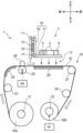
- 2 is a schematic cross-sectional view taken along line II-II in FIG. 1.
- FIG. 2 is an enlarged oblique view of a carriage of the inkjet printer.
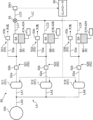
- 2 is a system diagram illustrating a schematic configuration of a liquid supply device mounted on the carriage.
- FIG. 4 is a system diagram showing a mechanical and electrical configuration of a pressurizing device in the liquid supply apparatus.
- FIG. 4 is a system diagram showing a mechanical and electrical configuration of a pressure reducing device in the liquid supply apparatus.
- FIG. FIG. 2 is a schematic diagram showing a configuration of a pressurizing pipe and a branch pipe in the pressurizing device.
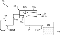
- 3 is a schematic diagram showing a structure of a vacuum ejector in the pressure reducing device.
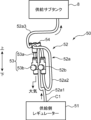
- FIG. FIG. 2 is a perspective view showing a layout of the pressurizing pipe and the branch pipe.
- an inkjet printer equipped with an ink head that ejects ink for forming an image onto a wide, long recording medium will be exemplified as a specific example of a recording device.
- Inkjet printers are suitable for digital textile printing, which uses an inkjet method to print images such as letters and patterns onto a recording medium made of fabric such as woven or knitted fabric.
- the recording device according to the present disclosure can also be used to print various images onto recording media such as paper sheets and resin sheets.
- FIG. 1 is a perspective view showing the overall configuration of an inkjet printer 1 according to an embodiment of the present disclosure
- FIG. 2 is a schematic cross-sectional view taken along line II-II in FIG. 1.
- the inkjet printer 1 is a printer that prints images on a wide and long workpiece W (recording medium) using an inkjet method. As an example, the width of the workpiece W is several meters.
- the printer 1 includes a device frame 10, and a work transport unit 20 and a carriage 3 that are incorporated into the device frame 10. Note that in this embodiment, the left-right direction is the main scanning direction S ( FIG. 3 ) when printing on the workpiece W, and the direction from the rear to the front is the sub-scanning direction (the transport direction F of the workpiece W, which intersects with the main scanning direction S).
- the device frame 10 forms a framework for mounting various components of the inkjet printer 1.
- the work transport unit 20 is a mechanism that intermittently feeds (transports) the work W so that the work W progresses in a transport direction F from rear to front in the printing area where the inkjet printing process is performed.
- the carriage 3 is equipped with an ink head 4, a pre-treatment liquid head 5 (FIG. 3), a post-treatment liquid head 6, and a liquid supply device 7, and moves back and forth in a main scanning direction S (left-right direction) that intersects with the transport direction F of the work W during the inkjet printing process.
- the ink head 4 corresponds to the "liquid ejection head" in this disclosure.
- the device frame 10 includes a central frame 111, a right frame 112, and a left frame 113.
- the central frame 111 forms a framework for mounting various components of the inkjet printer 1, and has a left-right width corresponding to the work transport section 20.
- the right frame 112 and the left frame 113 are erected to the right and left of the central frame 111, respectively. Between the right frame 112 and the left frame 113 is the printing area 12 where printing processing is performed on the work W.
- the right frame 112 forms the maintenance area 13.
- the maintenance area 13 is an area where the carriage 3 is retracted when the printing process is not being performed.
- cleaning and purging processes are performed on the nozzles (ejection holes) of the ink head 4, pre-treatment liquid head 5 and post-treatment liquid head 6, and caps are also fitted.
- the left frame 113 forms the turn-around area 14 for the carriage 3.
- the turn-around area 14 is an area where the carriage 3 temporarily enters when it performs a main scan in the opposite direction after performing a main scan in the opposite direction from right to left in the printing process.
- a carriage guide 15 is attached to the upper side of the device frame 10 to allow the carriage 3 to move back and forth in the left-right direction.
- the carriage guide 15 is a flat member that is long in the left-right direction, and is disposed above the work transport section 20.
- a timing belt 16 is attached to the carriage guide 15 so that it can move in a circular motion in the left-right direction (main scanning direction).
- the timing belt 16 is an endless belt that is driven to move in a circular motion in the left or right direction.
- the carriage guide 15 is equipped with a pair of upper and lower guide rails 17 that extend parallel to the left and right and that hold the carriage 3 in a state in which it can move back and forth in the main scanning direction S.
- the carriage 3 engages with the guide rails 17.
- the carriage 3 is also fixed to a timing belt 16. As the timing belt 16 moves orbitally to the left or right, the carriage 3 moves left or right along the carriage guide 15 while being guided by the guide rails 17.
- the work transport section 20 includes a feed roller 21 that pays out the work W before printing, and a take-up roller 22 that takes up the work W after printing.
- the feed roller 21 is located at the rear lower part of the device frame 10, and is a take-up shaft for the feed roll WA, which is a wound body of the work W before printing.
- the take-up roller 22 is located at the front lower part of the device frame 10, and is a take-up shaft for the take-up roll WB, which is a wound body of the work W after the printing process.
- a first motor M1 is attached to the take-up roller 22, which drives the take-up roller 22 to rotate around its axis and perform the winding operation of the work W.
- the path between the delivery roller 21 and the take-up roller 22 and passing through the printing area 12 is the transport path for the work W.
- a first tension roller 23 applies a predetermined tension to the work W on the upstream side of the transport roller 25.
- the work guide 24 changes the transport direction of the work W from upward to forward, allowing the work W to enter the printing area 12.
- the transport roller 25 is a roller that generates a transport force that intermittently feeds the workpiece W in the printing area 12.
- the transport roller 25 is driven to rotate about its axis by the second motor M2, and intermittently transports the workpiece W forward (predetermined transport direction F) so that the workpiece W passes through the printing area 12 (image forming position) facing the carriage 3.
- the pinch roller 26 is disposed to face the transport roller 25 from above, and forms a transport nip portion with the transport roller 25.
- the turn-back roller 27 changes the transport direction of the work W that has passed through the printing area 12 from the forward direction to the downward direction, and guides the work W after the printing process to the take-up roller 22.
- the second tension roller 28 applies a predetermined tension to the work W downstream of the transport roller 25.
- a platen 29 is disposed below the transport path of the work W in the printing area 12.
- the carriage 3 is supported at one end by the guide rail 17 and moves back and forth in the main scanning direction S (left and right in this embodiment) that intersects (orthogonal in this embodiment) with the transport direction F.
- the carriage 3 comprises a carriage frame 30, and an ink head 4, a pre-treatment liquid head 5, a post-treatment liquid head 6, and a liquid supply device 7 that are mounted on the carriage frame 30.
- the carriage frame 30 includes a head support frame 31 and a back frame 32.
- the head support frame 31 is a horizontal plate that holds the heads 4 to 6 described above.
- the back frame 32 is a vertical plate that extends upward from the rear edge of the head support frame 31.
- the timing belt 16 is fixed to the back frame 32.
- the guide rail 17 is engaged with the back frame 32. That is, in this embodiment, the back frame 32 is an engagement portion that holds the guide rail 17 in a cantilevered state.
- the head support frame 31 is a horizontal plate whose rear end side is supported in a cantilevered state on the guide rail 17 by the engagement portion described above.
- the cantilevered state refers to a state in which the engagement portion (back frame 32), which is the portion of the carriage 3 that is held by the guide rail 17, which is a holding member, is present only on one side, either upstream or downstream, from the center of the carriage 3 in the transport direction F, and no other engagement portion is present on the opposite side to the side where the engagement portion is present.
- the engagement portion may also be located outside the range in which the ink head 4 and processing head are located in the transport direction F. In other words, the engagement portion may be located only upstream or only downstream of the range in which the ink head 4 and processing head are located in the transport direction F.
- Fig. 3 is an enlarged perspective view of the carriage 3 shown in Fig. 1.
- Fig. 3 shows a transport direction F (sub-scanning direction) of the work W and a main scanning direction S which is a moving direction of the carriage 3.
- Fig. 3 shows an example in which a plurality of ink heads 4 which eject ink for image formation onto the work W, a pre-treatment liquid head 5 and a post-treatment liquid head 6 which eject a non-coloring treatment liquid, and a liquid supply device 7 which supplies the ink and treatment liquid to these heads 4 to 6 are mounted on the carriage 3.
- Each of the ink heads 4 has a number of nozzles (ink ejection holes) that eject ink droplets by an ejection method such as a piezoelectric method using a piezoelectric element or a thermal method using a heating element, and an ink passage that guides the ink to the nozzles.
- nozzles ink ejection holes
- an ejection method such as a piezoelectric method using a piezoelectric element or a thermal method using a heating element
- an ink passage that guides the ink to the nozzles.
- a water-based pigment ink containing a water-based solvent, pigment, and binding resin (binder) can be used as the ink.
- the multiple ink heads 4 in this embodiment are capable of ejecting eight colors of ink.
- the ink heads 4 are mounted on the head support frame 31 of the carriage 3 so as to be aligned in two rows in the main scanning direction S. Each color ink head 4 has two heads.
- the ink heads 4 include a first upstream ink head 41A and a first downstream ink head 42A. These ink heads 4 eject yellow ink.
- the ink heads 4 also include a second upstream ink head 41B and a second downstream ink head 42B. These ink heads 4 eject magenta ink.
- two ink heads 4 that eject ink of the same color are arranged at positions offset from each other in the transport direction F and the main scanning direction S. These two ink heads 4 are considered as one set, and a total of eight sets of ink heads 4 (41A to 41H, 42A to 42H) eject ink of different colors.
- the ink heads 4 include a first upstream ink head 41A to an eighth upstream ink head 41H and a first downstream ink head 42A to an eighth downstream ink head 42H.
- first upstream ink head 41A to the eighth upstream ink head 41H are referred to without distinction, they may be simply referred to as upstream ink head 41.
- first downstream ink head 42A to the eighth downstream ink head 42H may be simply referred to as downstream ink heads 42.
- the pre-treatment liquid head 5 and the post-treatment liquid head 6 are disposed at positions different from the ink head 4 in the transport direction F.
- the pre-treatment liquid head 5 is disposed upstream of the ink head 4 in the transport direction F.
- FIG. 3 shows an example in which one pre-treatment liquid head 5 is disposed near the left end of the array of ink heads 4.
- the post-treatment liquid head 6 is disposed downstream of the ink head 4 in the transport direction F.
- FIG. 3 shows an example in which one post-treatment liquid head 6 is disposed at the right end of the array of ink heads 4.
- multiple pre-treatment liquid heads 5 or multiple post-treatment liquid heads 6 may be disposed. It is desirable that the carriage 3 is provided with at least one pre-treatment liquid head 5 and at least one post-treatment liquid head 6, but in other embodiments, the pre-treatment liquid head 5 and the post-treatment liquid head 6 may not be disposed.
- the series of heads arranged along the main scanning direction S, which is made up of the ink heads 4, pretreatment liquid heads 5, and posttreatment liquid heads 6, is referred to as a row of heads, or simply as a row.
- the series of heads arranged along the transport direction F, which is made up of the ink heads 4, pretreatment liquid heads 5, and posttreatment liquid heads 6, is referred to as a row of heads, or simply as a row.
- the pretreatment liquid head 5 ejects pretreatment liquid for performing a predetermined pretreatment on the workpiece W.
- the pretreatment liquid is ejected from the ink head 4 onto a position on the workpiece W where ink has not yet been ejected from the ink head 4.
- the pretreatment liquid is a non-coloring treatment liquid that does not develop color even when it adheres to the workpiece W, and is a treatment liquid that exhibits functions such as increasing the fixation of ink to the workpiece W and the coagulation of ink pigments.
- a treatment liquid in which a binder resin is mixed into a solvent, or a treatment liquid in which a positively charged cationic resin is mixed into a solvent can be used.
- the post-treatment liquid head 6 ejects post-treatment liquid for performing a predetermined post-treatment on the workpiece W to which ink has been attached.
- the post-treatment liquid is ejected from the post-treatment liquid head 6 to a position on the workpiece W after the ink has been ejected from the ink head 4.
- the post-treatment liquid is a non-coloring treatment liquid that does not develop color even when it adheres to the workpiece W, and has the function of increasing the fixation and robustness (resistance to rubbing and scraping) of the ink image printed on the workpiece W by the ink head 4.
- a silicone-based treatment liquid or the like can be used as such a post-treatment liquid.
- the post-treatment liquid and the pre-treatment liquid are different treatment liquids. Specifically, the post-treatment liquid and the pre-treatment liquid contain different components.
- non-color-forming processing liquid refers to a liquid that, when printed alone on a recording medium, is not recognized as having color by the naked eye.
- Colors here include colors with a saturation of zero, such as black, white, and gray.
- Non-color-forming processing liquids are basically transparent liquids, but for example, when looking at 1 liter of processing liquid in liquid form, it is not completely transparent and may appear slightly white. Such colors are very light, so when printed alone on a recording medium, it is not recognized as having color by the naked eye. Note that, depending on the type of processing liquid, when printed alone on a recording medium, changes such as the appearance of gloss on the recording medium may occur, but this state is not color-forming.
- the pre-treatment liquid and the post-treatment liquid may be ejected onto substantially the entire surface of the workpiece W.
- the pre-treatment liquid and the post-treatment liquid may be ejected selectively in accordance with the image to be printed, similar to ink.
- the pretreatment liquid, ink, and posttreatment liquid are ejected in that order onto the workpiece W in the portion where the color is to be printed according to the image.
- the ink may be of one color or of multiple colors.
- the pretreatment liquid and posttreatment liquid are basically not ejected either. Note that in order to adjust the image quality of the printed image and the texture of the workpiece W, the selection of the ejection of the pretreatment liquid and posttreatment liquid may be made to differ from the ejection of the ink.
- openings 31H are provided at the locations of the heads on the head support frame 31.
- the ink head 4, pre-treatment liquid head 5, and post-treatment liquid head 6 are attached to the head support frame 31 so that they fit into the respective openings 31H.
- Nozzles arranged on the lower end surface of each of the heads 4, 5, and 6 are exposed from each opening 31H.
- the liquid supply device 7 includes a supply subtank 8 and a recovery subtank 9.
- the supply subtank 8 is a tank that stores liquid (ink or processing liquid) to be supplied to the heads 4, 5, and 6, and the recovery subtank 9 is a tank that stores the liquid recovered from the heads 4, 5, and 6. Both subtanks 8, 9 are supported by the carriage 3 with the recovery subtank 9 in front of the supply subtank 8. Note that the supply subtank 8 corresponds to the "supply tank” in this disclosure, and the recovery subtank 9 corresponds to the "recovery tank” in this disclosure.
- the supply subtank 8 has a first supply subtank 8A to an eighth supply subtank 8H, a pre-treatment supply subtank 81, and a post-treatment supply subtank 82 arranged along the main scanning direction S.
- Each supply subtank 8A to 8H, 81, and 82 is provided corresponding to each of the heads 4, 5, and 6. That is, the first supply subtank 8A to the eighth supply subtank 8H store ink to be supplied to the multiple ink heads 4 (41A to 41H, 42A to 42H).
- the pre-treatment supply subtank 81 stores pre-treatment liquid to be supplied to the pre-treatment liquid head 5.
- the post-treatment supply subtank 82 stores post-treatment liquid to be supplied to the post-treatment liquid head 6.
- the recovery subtank 9 has a first recovery subtank 9A to an eighth recovery subtank 9H, a pre-treatment recovery subtank 91, and a post-treatment recovery subtank 92 arranged along the main scanning direction S.
- Each recovery subtank 9A to 9H, 91, and 92 is provided corresponding to each of the heads 4, 5, and 6. That is, the first recovery subtank 9A to the eighth recovery subtank 9H each store ink recovered from the multiple ink heads 4 (41A to 41H, 42A to 42H).
- the pre-treatment recovery subtank 91 stores pre-treatment liquid recovered from the pre-treatment liquid head 5.
- the post-treatment recovery subtank 92 stores post-treatment liquid recovered from the post-treatment liquid head 6.
- the multiple sub-tanks mentioned above namely the supply sub-tanks 8A-8H, 81, 82 and the recovery sub-tanks 9A-9H, 91, 92, are supported by the carriage 3 above the heads 4, 5, 6 via a holding frame (not shown). Each sub-tank and the heads 4, 5, 6 are connected by conduits (not shown in FIG. 3).
- the first supply sub-tank 8A and first recovery sub-tank 9A located at the leftmost side of the carriage 3, store yellow ink containing pigment.
- the first supply sub-tank 8A supplies yellow ink to the first upstream ink head 41A and the first downstream ink head 42A.
- the first recovery sub-tank 9A stores yellow ink recovered from the first upstream ink head 41A and the first downstream ink head 42A. As described above, some of the yellow ink is ejected from the first upstream ink head 41A and the first downstream ink head 42A toward the workpiece W.
- the second supply sub-tank 8B supplies magenta ink to the second upstream ink head 41B and the second downstream ink head 42B.
- the second recovery sub-tank 9B stores magenta ink recovered from the second upstream ink head 41B and the second downstream ink head 42B.
- the other subtanks for ink i.e. the third supply subtank 8C to the eighth supply subtank 8H and the third recovery subtank 9C to the eighth recovery subtank 9H, have the same structure and function as described above.
- the pre-treatment supply sub-tank 81 supplies pre-treatment liquid to the pre-treatment liquid head 5, and the pre-treatment recovery sub-tank 91 recovers pre-treatment liquid from the pre-treatment liquid head 5.
- the post-treatment supply sub-tank 82 supplies post-treatment liquid to the post-treatment liquid head 6, and the post-treatment recovery sub-tank 92 recovers post-treatment liquid from the post-treatment liquid head 6.
- the inkjet printer 1 is an all-in-one printer in which three types of heads - the ink head 4, the pretreatment liquid head 5, and the posttreatment liquid head 6 - are mounted on a single carriage 3.
- the process of ejecting the pretreatment liquid and the process of ejecting the posttreatment liquid can be carried out in an integrated manner. This makes it possible to simplify the textile printing process and make the textile printing device more compact.
- the inkjet printer 1 uses a serial printing method to print on the workpiece W. Specifically, if the workpiece W is wide, it is not possible to print on the workpiece W while continuously feeding it.
- the serial printing method is a printing method that repeats the reciprocating movement of a carriage 3 carrying ink heads 4 of each color in the main scanning direction S and the intermittent feeding of the workpiece W in the transport direction F.
- the strip image is printed while the carriage 3 moves in the forward direction, which is one of the main scanning directions S.
- the feed of the workpiece W is stopped during this main scanning in the forward direction.
- the workpiece W is sent out in the transport direction F by a specified pitch.
- the carriage 3 waits in the turn-back area 14 on the left end side.
- the carriage 3 turns back in the return direction, which is opposite to the forward direction, as the timing belt 16 moves in reverse.
- the workpiece W is in a stopped state.
- the carriage 3 prints the next strip image upstream of the strip image. Similar operations are repeated thereafter.
- FIG. 4 is a system diagram that shows a schematic configuration of the liquid supply device 7.
- the lines connecting members indicate pipes (tubes) through which gas and liquid flow.
- FIG. 4 shows the flow of ink when ink is supplied to the ink heads 4 (41A to 41H, 42A to 42H) using the first supply subtank 8A to the eighth supply subtank 8H and the first recovery subtank 9A to the eighth recovery subtank 9H, but the pre-treatment liquid and the post-treatment liquid are also supplied to the pre-treatment liquid head 5 and the post-treatment liquid head 6 in the same structure as in FIG. 4.
- each treatment liquid is supplied in the same structure as in FIG. 4.
- the liquid supply device 7 includes a main tank 70, a main supply pump 71, and a circulation pump 72 in addition to the various sub-tanks described above. These elements are prepared for each color of ink. That is, one set of the main tank 70, the main supply pump 71, and the circulation pump 72 is prepared for the combination of the first supply sub-tank 8A and the first recovery sub-tank 9A that store yellow ink. Similarly, one set of the main tank 70, the main supply pump 71, and the circulation pump 72 is prepared for each combination of the supply sub-tanks 8B to 8H and the recovery sub-tanks 9B to 9H that store ink of other colors.
- first supply sub-tank 8A to the eighth supply sub-tank 8H when they are not differentiated from one another, they may simply be referred to as the supply sub-tank 8.
- first recovery sub-tank 9A to the eighth recovery sub-tank 9H when they are not differentiated from one another, they may simply be referred to as the recovery sub-tank 9.
- the main tank 70 is a tank that stores ink and is mounted on the device frame 10 ( Figure 1) outside the carriage 3.
- the main supply pump 71 is a pump that operates to supply ink in the main tank 70 to the supply subtank 8.
- the main supply pump 71 is connected to the supply subtank 8 via the ink refill path Q1.
- the circulation pump 72 is a pump that operates to return the ink in the recovery subtank 9 to the supply subtank 8.
- the circulation pump 72 is located midway along the ink return path Q4 that connects the supply subtank 8 and the recovery subtank 9.
- the supply subtank 8 and the recovery subtank 9 are connected to each other via the ink supply path Q2 and the ink recovery path Q3 that pass through the ink head 4 (41, 42).
- the downstream portion of the ink supply path Q2 branches into a first supply path Q2a that connects to the upstream ink head 41 and a second supply path Q2b that connects to the downstream ink head 42.
- the upstream portion of the ink recovery path Q3 branches into a second recovery path Q3a that connects to the upstream ink head 41 and a second supply path Q3b that connects to the downstream ink head 42.
- the liquid supply device 7 further includes a pressure applying device 50, a pressure reducing device 60, and a controller 90. These elements are common to each color of ink and treatment liquid (pre-treatment liquid and post-treatment liquid).
- the pressure applying device 50 is a device that applies positive pressure to the supply sub-tank 8 via air so that the inside of the supply sub-tank 8 (gas area SA described below) becomes a positive pressure higher than atmospheric pressure.
- the detailed structure of the pressure applying device 50 will be described later.
- the pressure reducing device 60 is a device that supplies negative pressure to the collection subtank 9 via air so that the inside of the collection subtank 9 (the gas area SC described below) becomes a negative pressure lower than atmospheric pressure.
- the detailed structure of the pressure reducing device 60 will be described later.
- the controller 90 is a device that controls the overall operation of the liquid supply device 7, and includes a processor, various memories, etc.
- the controller 90 controls the pressurizing device 50 and the decompressing device 60 so that the inside of the supply subtank 8 is maintained at a constant positive pressure and the inside of the recovery subtank 9 is maintained at a constant negative pressure.
- ink is supplied from each supply subtank 8 to each ink head 4 (41, 42), and ink is recovered from each ink head 4 to each recovery subtank 9.
- the recovered ink is returned to the supply subtank 8 as appropriate. That is, the ink circulates between the supply subtank 8 and the recovery subtank 9 while passing through the ink head 4.
- the supply subtank 8 has, for example, a box-like structure, and when ink is stored inside, a gas area SA and an ink area SB are formed.
- the gas area SA is an area (space) occupied by air above the ink level in the supply subtank 8, and the ink area SB is an area occupied by ink.
- the gas area SA is connected to the pressure device 50, and is maintained at a predetermined positive pressure by the pressure applied by the pressure device 50 through the air.
- the ink refill path Q1, ink supply path Q2, and ink return path Q4 described above are each connected to the ink area SB.
- the recovery subtank 9 has a box-like structure, and when ink is stored inside it, a gas region SC and an ink region SD are formed.
- the gas region SC is a region (space) above the ink level in the recovery subtank 9 that is occupied by air, and the ink region SD is a region occupied by ink.
- the gas region SC is connected to the pressure reducing device 60, and is maintained at a predetermined negative pressure by the pressure reduction through air by the pressure reducing device 60.
- the ink recovery path Q3 and ink return path Q4 described above are each connected to the ink region SD.
- the supply subtank 8 is fitted with a capacitance sensor SNa.
- the capacitance sensor SNa is a sensor capable of detecting the ink level (amount of ink) stored in the supply subtank 8.
- the recovery subtank 9 is fitted with a capacitance sensor SNb capable of detecting the ink level (amount of ink) inside.
- yellow ink is supplied from the main tank 70, which stores yellow ink, to the first supply sub-tank 8A through the ink refill path Q1.
- the yellow ink in the first supply sub-tank 8A is supplied to the first upstream ink head 41A and the first downstream ink head 42A through the ink supply path Q2.
- the remaining yellow ink is collected from the ink collection path Q3 into the first collection sub-tank 9A.
- the collected yellow ink is then returned to the first supply sub-tank 8A through the ink return path Q4.
- the circulation pump 72 operates in response to a command signal input from the controller 90. As a result, some of the yellow ink in the first recovery sub-tank 9A is returned to the first supply sub-tank 8A through the ink return path Q4.
- the circulation pump 72 operates whether the inkjet printer 1 is in the middle of a printing operation or not.
- the controller 90 determines based on the detection results of the capacitance sensors SNa and SNb that the amount of yellow ink in both the first supply sub-tank 8A and the first recovery sub-tank 9A falls below a preset threshold, the controller 90 operates the main supply pump 71 to replenish the yellow ink from the main tank 70 to the first supply sub-tank 8A through the ink refill path Q1.
- the above describes the circulation of yellow ink as a representative example, but similar circulation processes are performed for inks of other colors as well.
- the pre-treatment liquid and post-treatment liquid are also circulated by a similar mechanism. That is, the above-mentioned pressurizing device 50, decompressing device 60, main tank 70, main supply pump 71, and circulation pump 72 are also applied to circulate the pre-treatment liquid and post-treatment liquid.
- Fig. 5 is a system diagram showing the mechanical and electrical configurations of the pressurizing device 50
- Fig. 6 is a system diagram showing a schematic mechanical and electrical configurations of the decompression device 60.
- Fig. 5 illustrates the structure relating to pressurization of the first supply sub-tank 8A to the eighth supply sub-tank 8H in the pressurizing device 50, but the structure relating to pressurization of the other sub-tanks (pre-treatment supply sub-tank 81 and post-treatment supply sub-tank 82) is similar.
- Fig. 5 illustrates the structure relating to pressurization of the first supply sub-tank 8A to the eighth supply sub-tank 8H in the pressurizing device 50, but the structure relating to pressurization of the other sub-tanks (pre-treatment supply sub-tank 81 and post-treatment supply sub-tank 82) is similar.
- FIG. 6 illustrates the structure relating to decompression of the first recovery sub-tank 9A to the eighth recovery sub-tank 9H in the decompression device 60, but the structure relating to decompression of the other sub-tanks (pre-treatment recovery sub-tank 91 and post-treatment recovery sub-tank 92) is similar.
- the pressure device 50 supplies a predetermined positive pressure to the supply subtank 8 using air (gas) sent from a pressure source 100.
- the pressure source 100 can be of any type as long as it functions as a source of compressed air, but in this embodiment, an air compressor provided outside the inkjet printer 1 is used as the pressure source 100.
- the pressure source 100 is a source of compressed air used to operate various pneumatic devices in the factory facility in which the inkjet printer 1 is installed.
- the pressure applying device 50 includes a supply side regulator 51, a pressure applying pipe 52, and a branch pipe 53.
- the pressurizing device 50 has the first supply side regulator 511 to the eighth supply side regulator 518, the first pressure pipe 521 to the eighth pressure pipe 528, and the first branch pipe 531 to the eighth branch pipe 538 corresponding to the first supply sub-tank 8A to the eighth supply sub-tank 8H.
- the pressurizing device 50 has the first supply side regulator 511 to the eighth supply side regulator 518, the first pressure pipe 521 to the eighth pressure pipe 528, and the first branch pipe 531 to the eighth branch pipe 538 corresponding to the first supply sub-tank 8A to the eighth supply sub-tank 8H.
- FIG. 5 only the first supply sub-tank 8A, the second supply sub-tank 8B, and the eighth supply sub-tank 8H are shown, and the other supply sub-tanks (8C to 8G) are not shown.
- FIG. 5 corresponds the first supply sub-tank 8A, the second supply sub-tank 8B, and the eighth supply sub-tank 8H are shown, and the other supply sub-
- the supply-side regulator 51 restricts the flow of air sent from the pressure source 100 so that the pressure of the air is reduced.
- the supply-side regulator 51 is, for example, an electro-pneumatic regulator.
- the pressure of the air after reduction by the supply-side regulator 51 that is, the outlet pressure of the supply-side regulator 51, can be changed based on commands from the controller 90.
- the supply-side regulator 51 is connected to the pressure source 100 via a supply-side pressure supply path LA.
- the supply-side pressure supply path LA has a common path LA0 extending from the pressure source 100, and a first branch path LA1 to an eighth branch path LA8 branching from the common path LA0 toward the first supply-side regulator 511 to the eighth supply-side regulator 518.
- a primary regulator may be provided in the common path LA0. Note that in FIG. 5, only the first branch path LA1, the second branch path LA2, and the eighth branch path LA8 are shown corresponding to the first supply-side regulator 511, the second supply-side regulator 512, and the eighth supply-side regulator 518, and the other branch paths are not shown.
- the pressurizing pipe 52 is a pipe for sending the air after pressure reduction by the supply side regulator 51 to the supply sub-tank 8.
- the pressurizing pipe 52 has a first connecting pipe section 52a and a first throttle valve 52b provided in the middle of the first connecting pipe section 52a.
- the first connecting pipe section 52a is a tubular member that connects the regulator 51 and the gas area SA of the supply sub-tank 8.
- the first throttle valve 52b is a valve that adjusts the flow rate of air flowing through the first connecting pipe section 52a by narrowing the flow path of the first connecting pipe section 52a.
- the first throttle valve 52b is a resistance component (resistance section) also known as a speed controller, and has a larger fluid resistance than the first connecting pipe section 52a.
- the first throttle valve 52b corresponds to the "first resistance section" in this disclosure.
- the branch pipe 53 is a pipe that branches off from the middle of the pressurized pipe 52.
- the branch pipe 53 has a second connecting pipe section 53a and a second throttle valve 53b provided at the end of the second connecting pipe section 53a.
- the second connecting pipe section 53a is a tubular member that branches off from a position downstream of the first throttle valve 52b in the first connecting pipe section 52a of the pressurized pipe 52 and extends.
- the end of the branch pipe 53, here the outlet of the second throttle valve 53b, is open to the atmosphere.
- the second throttle valve 53b is a flow rate adjustable valve similar to the first throttle valve 52b of the pressurized pipe 52, and functions as a resistance component (resistance section) having a larger fluid resistance than the second connecting pipe section 53a.
- the second throttle valve 53b corresponds to the "second resistance section" in this disclosure.
- the branch pipe 53 may have a pipe (extension pipe) that extends further downstream from the second throttle valve 53b. Also, if an opening to the atmosphere is formed midway along this extension tube, this opening to the atmosphere can be considered as the end of the branch tube 53.
- FIG. 7 is a schematic diagram showing the configuration of the pressurizing pipe 52 and the branch pipe 53.
- the first throttle valve 52b of the pressurizing pipe 52 and the second throttle valve 53b of the branch pipe 53 are each shown as elements that mimic the resistance of an electrical circuit.
- the fluid resistance of the first throttle valve 52b is R1
- the fluid resistance of the second throttle valve 53b is R2.
- the outlet pressure of the supply side regulator 51 is PAout
- the outlet pressure of the pressurizing pipe 52 in other words the inlet pressure of the supply sub-tank 8, is PAin.
- the fluid resistance R1 of the first throttle valve 52b is abbreviated to the first resistance R1
- the fluid resistance R2 of the second throttle valve 53b is abbreviated to the second resistance R2.
- the outlet pressure PAout of the supply side regulator 51 is abbreviated as the supply side regulated pressure PAout
- the inlet pressure PAin of the supply subtank 8 is abbreviated as the supply subtank pressure PAin.
- the supply side regulated pressure PAout is adjusted to a substantially constant value by PID control by the controller 90.
- the air discharged from the supply side regulator 51 is introduced into the supply sub-tank 8 while being reduced in pressure as it passes through the pressure pipe 52.
- the supply sub-tank pressure PAin decreases at a predetermined rate relative to the supply side regulated pressure PAout. This rate of decrease is determined by the first resistor R1 and the second resistor R2.
- the values of the first resistance R1 and the second resistance R2 are preset so that the supply subtank pressure PAin becomes a desired value.
- the resistance ratio is set to 1/5 or more and 1/50 or less.
- the opening degrees of the first throttle valve 52b and the second throttle valve 53b are set so that the value obtained by dividing the fluid resistance (R2) of the second throttle valve 53b by the total fluid resistance (R1+R2) of the first throttle valve 52b and the second throttle valve 53b becomes 1/5 to 1/50.
- the fluid resistance of the entire pressurizing pipe 52 is substantially governed by the fluid resistance (first resistance R1) of the first throttle valve 52b
- the end of the branch pipe 53 is open to the atmosphere, and the pressure there is atmospheric pressure (0 kPa).
- the supply side regulated pressure PAout is set to +45 kPa (gauge pressure).
- the supply subtank pressure PAin in other words the pressure of the gas area SA of the supply subtank 8, is set to +1.5 kPa (gauge pressure).
- the supply subtank 8 is connected to the first pressure sensor SN1 via the first extraction path LC.
- the first extraction path LC has a first branch path LC1 to an eighth branch path LC8 that extend from each of the gas areas SA of the first supply subtank 8A to the eighth supply subtank 8H, respectively, and a common path LC0 that connects the junction where these branch paths LC1 to LC8 join with the first pressure sensor SN1.
- a switching valve 55 is provided at the junction of the branch paths LC1 to LC8. Note that FIG.
- FIG 5 shows only the first branch path LC1, the second branch path LC2, and the eighth branch path LC8 corresponding to the first supply subtank 8A, the second supply subtank 8B, and the eighth supply subtank 8H, and does not show the other branch paths.
- the switching valve 55 is a valve that selectively connects the first branch path LC1 to the eighth branch path LC8 to the common path LC0. For example, when the switching valve 55 operates so that the first branch path LC1 connects to the common path LC0, the communication between the other branch paths (LC2 to LC8) and the common path LC0 is blocked. In this state, the first supply subtank 8A and the first pressure sensor SN1 communicate via the first branch path LC1 and the common path LC0. In this way, the switching valve 55 has the function of selectively connecting each gas area SA of the first supply subtank 8A to the eighth supply subtank 8H to the first pressure sensor SN1. This selective communication allows the first pressure sensor SN1 to detect the pressure (supply subtank pressure PAin) of the gas area SA in the desired tank selected from the first supply subtank 8A to the eighth supply subtank 8H.
- the controller 90 adjusts the outlet pressure of the supply-side regulator 51, i.e., the supply-side regulated pressure PAout, based on the pressure of the gas area SA of the supply sub-tank 8 (8A-8H) detected by the first pressure sensor SN1 as described above. That is, the controller 90 adjusts the supply-side regulated pressure PAout by PID control (feedback control) of the supply-side regulator 51 based on the output of the first pressure sensor SN1, so that the pressure of the supply sub-tank 8 (gas area SA) matches a predetermined target value. As an example, if the target value is +1.5 kPa, the controller 90 adjusts the supply-side regulated pressure PAout so that the pressure of the supply sub-tank 8 is maintained at around +1.5 kPa.
- PID control feedback control
- the pressure reducing device 60 supplies a predetermined negative pressure to the collection sub-tank 9 using air (gas) sent from a pressure source 100.
- the pressure source 100 is the same as the pressure source 100 used in the pressurizing device 50 described above.
- the pressure reducing device 60 includes a recovery side regulator 61, an outlet pipe 62, a vacuum ejector 63, and a connecting pipe 64.
- the pressure reducing device 60 has the first recovery side regulator 611 to the eighth recovery side regulator 618, the first outlet pipe 621 to the eighth outlet pipe 628, the first vacuum ejector 631 to the eighth vacuum ejector 638, and the first connection pipe 641 to the eighth connection pipe 648 corresponding to the first recovery subtank 9A to the eighth recovery subtank 9H.
- the first recovery subtank 9A, the second recovery subtank 9B, and the eighth recovery subtank 9H are shown, and the other recovery subtanks (9C to 9G) are omitted.
- the recovery side regulator 61 is similar to the supply side regulator 51 described above, and is, for example, an electro-pneumatic regulator.
- the air pressure after reduction by the recovery side regulator 61 i.e., the outlet pressure of the recovery side regulator 61, can be changed based on a command from the controller 90.
- the recovery side regulator 61 is connected to the pressure source 100 via a recovery side pressure supply line LB.
- the recovery side pressure supply line LB has a common line LB0 extending from the pressure source 100, and a first branch line LB1 to an eighth branch line LB8 branching from the common line LB0 toward the first recovery side regulator 611 to the eighth recovery side regulator 618.
- a primary regulator may be provided in the common line LB0. Note that in FIG. 6, only the first branch line LB1, the second branch line LB2, and the eighth branch line LB8 are shown corresponding to the first recovery side regulator 611, the second recovery side regulator 612, and the eighth recovery side regulator 618, and the other branch lines are not shown.
- the discharge pipe 62 is a pipe extending from the recovery side regulator 61, and a vacuum ejector 63 is connected to its end.
- FIG. 8 is a schematic diagram showing the structure of the vacuum ejector 63.
- the vacuum ejector 63 has a nozzle 63a, a diffuser 63b, and a negative pressure port 63c.
- the nozzle 63a is a flow path formed so that the cross-sectional area becomes narrower toward the downstream side.
- the nozzle 63a is connected to the end of the outlet pipe 62.
- the diffuser 63b is a passage formed coaxially on the downstream side of the nozzle 63a, and has an upstream part that contains the outlet of the nozzle 63a and a downstream part whose cross-sectional area increases toward the downstream side.
- the outlet of the diffuser 63b is open to the atmosphere.
- the negative pressure port 63c is a port that communicates with the upstream part of the diffuser 63b.
- the negative pressure port 63c communicates with the upstream part of the diffuser 63b from a direction perpendicular to the axial direction of the nozzle 63a and the diffuser 63b.
- the air that flows into the nozzle 63a from the outlet pipe 62 increases in flow rate as it passes through the nozzle 63a, and is ejected from the outlet of the nozzle 63a at extremely high speed.
- the air ejected from the nozzle 63a is discharged to the outside air after its flow rate is reduced downstream of the diffuser 63b.
- a strong negative pressure is generated around the outlet of the nozzle 63a, which is the air ejection port. This makes the pressure at the negative pressure port 63c connected to the upstream part of the diffuser 63b negative.
- connection pipe 64 is a pipe that connects the negative pressure port 63c of the vacuum ejector 63 to the gas area SC of the recovery sub-tank 9. Negative pressure is supplied from the vacuum ejector 63 to the recovery sub-tank 9 through this connection pipe 64.
- the outlet pressure of the recovery side regulator 61 is PBout
- the outlet pressure of the connecting pipe 64 in other words the inlet pressure of the recovery sub-tank 9
- PBin the outlet pressure of the recovery side regulator 61
- the inlet pressure PBin of the recovery sub-tank 9 is abbreviated to the recovery sub-tank pressure PBin.
- the recovery side regulated pressure PBout is adjusted to a substantially constant value that is sufficiently higher than atmospheric pressure by PID control by the controller 90.
- the recovery side regulated pressure PBout is set to a value higher than the above-mentioned supply side regulated pressure PAout (+45 kPa in one example).
- the air with the pressure of PBout flows through the outlet pipe 62 into the nozzle 63a of the vacuum ejector 63, and is ejected at high speed from the outlet of the nozzle 63a. This makes the pressure at the negative pressure port 63c negative. This negative pressure is transmitted to the recovery subtank 9 through the connection pipe 64, making the recovery subtank pressure PBin negative.
- the absolute value of the recovery subtank pressure PBin is smaller than the recovery side regulated pressure PBout.
- the recovery side regulated pressure PBout is set to +160 kPa (gauge pressure).
- the recovery subtank pressure PBin in other words the pressure in the gas area SC of the recovery subtank 9, becomes a negative pressure of, for example, about -16 kPa.
- the absolute value of this recovery side pressure change rate ⁇ Pb is sufficiently smaller than 1.
- the recovery side pressure change rate ⁇ Pb changes to some extent depending on the value of the recovery side regulated pressure PBout, but for example, in the actual usage range where the pressure PBout is around +160 kPa, the recovery side pressure change rate ⁇ Pb is about -0.1. This means that when the recovery side regulated pressure PBout changes by +1 kPa, the recovery subtank pressure PBin changes by approximately -0.1 kPa.
- the recovery side pressure change rate ⁇ Pb is less than 1, it becomes possible to adjust the pressure in the recovery subtank 9 (recovery subtank pressure PBin) in finer units than the pressure adjustment unit by the recovery side regulator 61 itself.
- the recovery side pressure change rate ⁇ Pb is less than 1, it becomes possible to adjust the pressure in the recovery subtank 9 in units of less than 1 kPa.
- the supply-side pressure change rate ⁇ Pa which is the ratio of the change in the supply sub-tank pressure PAin to the change in the supply-side regulated pressure PAout, is also set to a value significantly smaller than 1. That is, in this embodiment, the supply-side pressure change rate ⁇ Pa and the recovery-side pressure change rate ⁇ Pb are set to values of the same order of magnitude. In other words, the supply-side pressure change rate ⁇ Pa and the recovery-side pressure change rate ⁇ Pb are set to satisfy the relationship of the following formula (1). -0.1 ⁇ Pb ⁇ Pa ⁇ -10 ⁇ Pb (1)
- the recovery subtank 9 is connected to the second pressure sensor SN2 via the second extraction path LD.
- the second extraction path LD has a first branch path LD1 to an eighth branch path LD8 that extend from each of the gas regions SC of the first recovery subtank 9A to the eighth recovery subtank 9H, respectively, and a common path LD0 that connects the junction where these branch paths LD1 to LD8 join with the second pressure sensor SN2.
- a switching valve 65 is provided at the junction of the branch paths LD1 to LD8. Note that in FIG.
- the switching valve 65 is a valve similar to the supply side switching valve 55 described above, and selectively connects the first branch path LD1 to the eighth branch path LD8 to the common path LD0. This selective connection by the switching valve 65 allows the second pressure sensor SN2 to detect the pressure of the gas region SC (recovery subtank pressure PBin) in the desired tank selected from the first recovery subtank 9A to the eighth recovery subtank 9H.
- SC recovery subtank pressure PBin
- the controller 90 adjusts the outlet pressure of the recovery regulator 61, i.e., the recovery regulated pressure PBout, based on the pressure of the gas region SC of the recovery subtank 9 (9A-9H) detected by the second pressure sensor SN2 as described above. That is, the controller 90 adjusts the recovery regulated pressure PBout by PID control (feedback control) of the recovery regulator 61 based on the output of the second pressure sensor SN2 so that the pressure of the recovery subtank 9 (gas region SC) matches a predetermined target value. As an example, if the target value is -16 kPa, the controller 90 adjusts the recovery regulated pressure PBout so that the pressure of the recovery subtank 9 is maintained near -16 kPa.
- PID control feedback control
- [Relationship between the atmospheric release position and the supply side regulator] 9 is a perspective view showing the layout of the pressurizing pipe 52 and the branch pipe 53 in the pressurizing device 50.
- the supply-side regulator 51 is disposed below the supply sub-tank 8.
- the first throttle valve 52b of the pressurizing pipe 52 and the second throttle valve 53b of the branch pipe 53 are disposed between the supply-side regulator 51 and the supply sub-tank 8 in a side-by-side relationship.
- a joint 54 is disposed above the second throttle valve 53b. The joint 54 functions as a branch point between the pressurizing pipe 52 and the branch pipe 53.
- the first connecting pipe section 52a of the pressurizing pipe 52 is arranged to extend from the supply side regulator 51 through the first throttle valve 52b and the joint 54 to the supply sub-tank 8. That is, the first connecting pipe section 52a has an upstream tube 52a1 that connects the supply side regulator 51 to the upper end (inlet) of the first throttle valve 52b, a relay tube 52a2 that connects the lower end (outlet) of the first throttle valve 52b to the joint 54, and a downstream tube 52a3 that connects the joint 54 to the supply sub-tank 8.
- Each of the tubes 52a1, 52a2, 52a3 is arranged to extend vertically while being bent or changed in direction as appropriate.
- the second connecting pipe section 53a of the branch pipe 53 is disposed so as to extend downward from the joint 54.
- the lower end of this second connecting pipe section 53a is connected to the upper end (inlet) of the second throttle valve 53b.
- the lower end (outlet) of the second throttle valve 53b is open to the atmosphere above the supply side regulator 51.
- the end of the branch pipe 53 i.e., the atmosphere opening port, is located higher than the connection C1 between the pressurizing pipe 52 and the supply side regulator 51.
- the pressurizing device 50 includes a supply-side regulator 51 that reduces the pressure of the air sent from the pressure source 100, a pressurizing pipe 52 that connects the supply-side regulator 51 and the supply subtank 8, and a branch pipe 53 that branches off from the middle of the pressurizing pipe 52 and is open to the atmosphere at its end.
- This configuration has the advantage of improving the accuracy of pressure adjustment in the supply subtank 8.
- the pressure pipe 52 is interposed between the supply side regulator 51 and the supply subtank 8, and the end of the branch pipe 53 that branches off from the middle of the pressure pipe 52 is open to the atmosphere, so that the pressure supplied from the outlet of the pressure pipe 52 to the supply subtank 8 is lower than the outlet pressure of the supply side regulator 51 by a predetermined ratio.
- the pressure reduction rate is determined based on the fluid resistance of the pressure pipe 52 and the branch pipe 53, so that the desired positive pressure can be supplied to the supply subtank 8 by adjusting each fluid resistance.
- the supply side pressure change rate ⁇ Pa which is the ratio of the change in the pressure of the supply subtank 8 (supply subtank pressure PAin) to the change in the outlet pressure of the supply side regulator (supply side regulated pressure PAout), becomes a value significantly smaller than 1. Therefore, the pressure of the supply subtank 8 can be adjusted in a finer unit than the pressure adjustment unit by the supply side regulator 51 itself, and the pressure of the supply subtank 8 can be accurately kept close to the target value.
- negative pressure is supplied from the pressure reducing device 60 to the collection subtank 9 via air (gas) so that the inside of the collection subtank 9 becomes a negative pressure lower than atmospheric pressure.
- the pressure reducing device 60 includes a collection side regulator 61 that reduces the pressure of the air sent from the pressure source 100, a vacuum ejector 63 that generates negative pressure using the flow of air flowing in from the collection side regulator 61, and a connecting pipe 64 that connects the negative pressure port 63c of the vacuum ejector 63 to the collection subtank 9. This configuration has the advantage of improving the accuracy of pressure adjustment in the collection subtank 9.
- the absolute value of the pressure at the negative pressure port 63c of the vacuum ejector 63 becomes sufficiently smaller than the inlet pressure of the vacuum ejector 63.
- a negative pressure with an absolute value sufficiently smaller than the outlet pressure of the recovery side regulator 61 is applied to the recovery subtank 9.
- the absolute value of the recovery side pressure change rate ⁇ Pb which is the ratio of the change in the pressure of the recovery subtank 9 (recovery subtank pressure PBin) to the change in the outlet pressure of the recovery side regulator 61 (recovery side regulated pressure PBout) becomes sufficiently smaller than 1. This makes it possible to adjust the pressure of the recovery subtank 9 in finer units than the pressure adjustment unit by the recovery side regulator 61 itself, and to precisely keep the pressure of the recovery subtank 9 close to the target value.
- positive pressure is supplied from the pressure device 50 to the supply subtank 8, and negative pressure is supplied from the pressure reducing device 60 to the recovery subtank 9.
- This configuration makes it easy to increase the pressure difference between the supply subtank 8 and the recovery subtank 9, and can increase the upper limit of the amount of ink that can be circulated between the two tanks 8, 9. This makes it possible to increase the upper limit of the amount of ink that can be ejected from the ink head 4 per unit time, improving printing performance.
- a first throttle valve 52b is provided in the pressurizing pipe 52
- a second throttle valve 53b is provided in the branch pipe 53.
- the first throttle valve 52b can function as a resistance component that substantially controls the fluid resistance of the pressurizing pipe 52
- the second throttle valve 53b can function as a resistance valve that substantially controls the fluid resistance of the branch pipe 53.
- the fluid resistances of the pressurizing pipe 52 and the branch pipe 53 can be easily changed, and the supply side pressure change rate ⁇ Pa described above can be adjusted accordingly. This allows the unit of pressure adjustment of the supply subtank 8 to be reduced to a desired level, and the pressure of the supply subtank 8 can be adjusted with precision.
- the resistance ratio obtained by dividing the second resistance R2 by the sum of the first resistance R1 and the second resistance R2 (R1+R2) is set in the range of 1/5 to 1/50.
- the pressure of the supply subtank 8 (supply subtank pressure PAin) can be reduced to 1/5 to 1/50 of the outlet pressure of the supply side regulator 51 (supply side regulated pressure PAout), thereby improving the pressure adjustment accuracy of the supply subtank 8.
- the branch pipe 53 branches downward from the pressure pipe 52.
- the end of the branch pipe 53 which is the air opening, is located at a higher position than the connection C1 ( Figure 9) between the pressure pipe 52 and the supply-side regulator 51.
- the outlet pressure of the supply side regulator 51 is adjusted based on the pressure of the supply sub-tank 8 detected by the first pressure sensor SN1
- the outlet pressure of the recovery side regulator 61 is adjusted based on the pressure of the recovery sub-tank 9 detected by the second pressure sensor SN2.
- the pressure source 100 consisting of an air compressor provided outside the inkjet printer 1 is used as the source of compressed air used in the pressure device 50 and the pressure reduction device 60, but the source of compressed air is not limited to this.
- an air pressure pump that pressurizes and delivers air may be built into the inkjet printer 1 as the source of compressed air.
- positive pressure is supplied from the pressurizing device 50 to the supply sub-tank 8 via air
- negative pressure is supplied from the decompression device 60 to the recovery sub-tank 9 via air
- the medium for transmitting pressure to both tanks 8, 9 need only be gas and is not limited to air.
- pressure may be supplied to both tanks 8, 9 via a gas such as nitrogen gas.
- throttle valves 52b, 53b are provided in the pressurizing pipe 52 and the branch pipe 53 of the pressurizing device 50, respectively, but orifices may be provided instead of the throttle valves 52b, 53b.
- proportional valves whose opening can be electrically controlled may be provided instead of the throttle valves 52b, 53b.
- the parts that function as the main resistance components in the pressurizing pipe 52 and the branch pipe 53 i.e., the resistance parts, may have a larger fluid resistance than the parts other than the resistance parts (base pipe parts 52a, 53a), and the type of resistance parts may be changed as appropriate.
- the ink heads 4 are not limited to being arranged in two rows on the carriage 3.
- the ink heads 4 may be arranged in a single row, or in three or more rows.
- the inkjet printer 1 is not limited to being configured to be capable of ejecting ink of multiple colors onto the workpiece W, and may be configured to eject ink of a single color.
- the inkjet printer 1 may not have the pre-treatment liquid head 5 that ejects the pre-treatment liquid, the post-treatment liquid head 6 that ejects the post-treatment liquid, or any of the components associated with these.
- Inkjet printer (recording device) 4. Ink head (liquid ejection head) 7 Liquid supply device 8 Supply sub-tank (supply tank) 9. Recovery subtank (recovery tank) 50 Pressurizing device 51 Supply side regulator 52 Pressurizing pipe 52a First base pipe section 52b First throttle valve (first resistance section) 53 Branch pipe 53a Second connecting pipe section 53b Second throttle valve (second resistance section) 60 Pressure reducing device 61 Recovery side regulator 63 Vacuum ejector 64 Connection pipe 90 Controller C1 Connection portion SN1 First pressure sensor SN2 Second pressure sensor
Landscapes
- Ink Jet (AREA)
Abstract
液体供給装置は、液体吐出ヘッドに供給される液体を貯留する供給タンクと、供給タンクの内部が大気圧よりも高い正圧になるように、当該供給タンクに気体を介して正圧を供給する加圧装置とを備える。加圧装置は、圧力源から送られてきた気体の圧力を低下させる供給側レギュレータと、供給側レギュレータによる減圧後の気体が供給タンクに送られるように供給側レギュレータと供給タンクとを繋ぐ加圧管と、加圧管の途中から分岐して延び、終端が大気に開放された分岐管とを含む。
Description
本開示は、液体供給装置及びこれを備えた記録装置に関する。
上記記録装置の一種として、下記特許文献1に記載のインクジェット式プリンター(印刷装置)が知られている。このインクジェット式プリンターは、インクを記録媒体(印刷媒体)に吐出する吐出ヘッドと、吐出ヘッドにインクを供給する液体供給装置(インク供給装置)とを備える。液体供給装置は、吐出ヘッドに供給される液体が貯留される供給タンクと、吐出ヘッドから回収された液体が貯留される回収タンクと、回収タンク内のインクを供給タンクに還流する循環ポンプと、供給タンクに負圧を与える負圧ポンプ等からなる供給側負圧供給部と、回収タンクに負圧を与える負圧ポンプ等からなる回収側負圧供給部とを備える。
上記インクジェット式プリンターの印刷処理時は、供給タンクと回収タンクとの間に所定の圧力差が生じるように供給側負圧供給部及び回収側負圧供給部が制御される。この圧力差によって、吐出ヘッドを介して供給タンクから回収タンクにインクが移動する。移動したインクは、循環ポンプによって回収タンクから供給タンクに戻される。
本開示の一局面に係る液体供給装置は、液体吐出ヘッドに供給される液体を貯留する供給タンクと、前記供給タンクの内部が大気圧よりも高い正圧になるように、当該供給タンクに気体を介して正圧を供給する加圧装置とを備え、前記加圧装置は、所定の圧力源から送られてきた気体の圧力が低下するように当該気体の流れを制限する供給側レギュレータと、前記供給側レギュレータによる減圧後の気体が前記供給タンクに送られるように前記供給側レギュレータと前記供給タンクとを繋ぐ加圧管と、前記加圧管の途中から分岐して延び、終端が大気に開放された分岐管とを含むものである。
また、本開示の他の局面に係る記録装置は、前記液体としてのインクを供給する上述した液体供給装置と、前記液体供給装置から供給されたインクを所定の記録媒体に吐出する前記液体吐出ヘッドとを備えたものである。
以下、図面を参照しつつ、本開示の一実施形態に係る記録装置ついて説明する。以下の実施形態では、記録装置の具体例として、広幅で長尺の記録媒体に画像形成用のインクを吐出するインクヘッドを備えたインクジェット式プリンターを例示する。インクジェット式プリンターは、織物や編物等の生地からなる記録媒体に、文字類や模様等の画像をインクジェット方式で印刷するデジタル捺染印刷に好適である。もちろん、本開示に係る記録装置は、紙シートや樹脂シート等の記録媒体に各種の画像を印刷する用途にも用いることができる。
[インクジェット式プリンターの全体構成]
図1は、本開示の一実施形態に係るインクジェット式プリンター1の全体構成を示す斜視図であり、図2は、図1のII-II線に沿った模式的な断面図である。インクジェット式プリンター1は、広幅且つ長尺のワークW(記録媒体)にインクジェット方式で画像を印刷するプリンターである。一例として、ワークWの幅は、数メートルに及ぶ。プリンター1は、装置フレーム10と、この装置フレーム10に組み込まれたワーク搬送部20及びキャリッジ3とを含む。なお、本実施形態では、左右方向がワークWに対する印刷の際の主走査方向S(図3)、後方から前方に向かう方向が副走査方向(主走査方向Sと交差する方向であるワークWの搬送方向F)である。
図1は、本開示の一実施形態に係るインクジェット式プリンター1の全体構成を示す斜視図であり、図2は、図1のII-II線に沿った模式的な断面図である。インクジェット式プリンター1は、広幅且つ長尺のワークW(記録媒体)にインクジェット方式で画像を印刷するプリンターである。一例として、ワークWの幅は、数メートルに及ぶ。プリンター1は、装置フレーム10と、この装置フレーム10に組み込まれたワーク搬送部20及びキャリッジ3とを含む。なお、本実施形態では、左右方向がワークWに対する印刷の際の主走査方向S(図3)、後方から前方に向かう方向が副走査方向(主走査方向Sと交差する方向であるワークWの搬送方向F)である。
装置フレーム10は、インクジェット式プリンター1の各種構成部材を搭載するための骨組みを形成している。ワーク搬送部20は、インクジェット印刷処理が行われる印刷領域においてワークWが、後方から前方に向かう搬送方向Fに進行するように、当該ワークWを間欠送りする(搬送する)機構である。キャリッジ3は、インクヘッド4、前処理液ヘッド5(図3)、後処理液ヘッド6、及び液体供給装置7を搭載し、上記インクジェット印刷処理の際にワークWの搬送方向Fと交差する主走査方向S(左右方向)に往復移動する。なお、インクヘッド4は、本開示における「液体吐出ヘッド」に相当する。
装置フレーム10は、中央フレーム111、右フレーム112及び左フレーム113を含む。中央フレーム111は、インクジェット式プリンター1の各種構成部材を搭載するための骨組みを形成しており、ワーク搬送部20に応じた左右幅を有している。右フレーム112及び左フレーム113は、それぞれ中央フレーム111の右隣、左隣に立設されている。右フレーム112と左フレーム113との間が、ワークWに対して印刷処理が実行される印刷エリア12である。
右フレーム112は、メンテナンスエリア13を形成する。メンテナンスエリア13は、上記印刷処理が実行されないときに、キャリッジ3を退避させるエリアである。メンテナンスエリア13では、インクヘッド4、前処理液ヘッド5及び後処理液ヘッド6のノズル(吐出孔)のクリーニング処理、パージ処理等が行われ、またキャップが被嵌される。左フレーム113は、キャリッジ3の折り返しエリア14を形成する。折り返しエリア14は、上記印刷処理において右方から左方へ印刷エリア12を主走査したキャリッジ3が、逆方向の主走査を行う際に一時的に入る領域である。
装置フレーム10の上方側には、キャリッジ3に左右方向の往復移動を行わせるためのキャリッジガイド15が組み付けられている。キャリッジガイド15は、左右方向に長い平板状の部材であり、ワーク搬送部20の上方に配置されている。キャリッジガイド15には、タイミングベルト16が左右方向(主走査方向)に周回移動が可能に組み付けられている。タイミングベルト16は、無端ベルトであって、左方向又は右方向に周回移動するよう駆動される。
キャリッジガイド15には、キャリッジ3を主走査方向Sに往復移動が可能な状態で保持する上下一対のガイドレール17が、左右方向に平行に延在するように装備されている。キャリッジ3は、ガイドレール17と係合している。また、キャリッジ3は、タイミングベルト16に固定されている。キャリッジ3は、タイミングベルト16の左方向又は右方向の周回移動に伴って、ガイドレール17に案内されつつ、キャリッジガイド15に沿って左方向又は右方向に移動する。
図2を主に参照して、ワーク搬送部20は、印刷前のワークWを繰り出す送り出しローラー21と、印刷後のワークWを巻き取る巻き取りローラー22とを含む。送り出しローラー21は、装置フレーム10の後方下部に配置され、印刷前のワークWの巻回体である送り出しロールWAの巻き取り軸である。巻き取りローラー22は、装置フレーム10の前方下部に配置され、印刷処理後のワークWの巻回体である巻き取りロールWBの巻き取り軸である。巻き取りローラー22には、当該巻き取りローラー22を軸回りに回転駆動し、ワークWの巻き取り動作を実行させる第1モーターM1が付設されている。
送り出しローラー21と巻き取りローラー22との間であって印刷エリア12を通る経路が、ワークWの搬送経路となる。この搬送経路には、上流側から順に第1テンションローラー23、ワークガイド24、搬送ローラー25及びピンチローラー26、折り返しローラー27、第2テンションローラー28が配置されている。第1テンションローラー23は、搬送ローラー25の上流側において、ワークWに所定の張力を付与する。ワークガイド24は、ワークWの搬送方向を上方向から前方向に変更し、ワークWを印刷エリア12へ搬入させる。
搬送ローラー25は、印刷エリア12においてワークWを間欠送りする搬送力を発生するローラーである。搬送ローラー25は、第2モーターM2により軸回りに回転駆動され、ワークWがキャリッジ3に対向する印刷エリア12(画像形成位置)を通過するように、ワークWを前方向(所定の搬送方向F)に間欠的に搬送する。ピンチローラー26は、搬送ローラー25に対して上方から対向するように配置され、搬送ローラー25と搬送ニップ部を形成している。
折り返しローラー27は、印刷エリア12を通過したワークWの搬送方向を前方向から下方向に変更し、印刷処理後のワークWを巻き取りローラー22へ導く。第2テンションローラー28は、搬送ローラー25の下流側において、ワークWに所定の張力を付与する。印刷エリア12においてワークWの搬送経路の下方には、プラテン29が配置されている。
キャリッジ3は、ガイドレール17に片持ち支持された状態で、搬送方向Fと交差(本実施形態では直交)する主走査方向S(本実施形態では左右方向)に往復移動する。キャリッジ3は、キャリッジフレーム30と、このキャリッジフレーム30に搭載されるインクヘッド4、前処理液ヘッド5、後処理液ヘッド6及び液体供給装置7とを備える。キャリッジフレーム30は、ヘッド支持フレーム31及びバックフレーム32を含む。
ヘッド支持フレーム31は、上述したヘッド4~6を保持する水平板である。バックフレーム32は、ヘッド支持フレーム31の後端縁から上方に延びる垂直板である。上述したように、タイミングベルト16は、バックフレーム32に固定されている。また、ガイドレール17は、バックフレーム32に係合されている。すなわち、本実施形態では、バックフレーム32がガイドレール17に片持ち状態で保持される係合部である。ヘッド支持フレーム31は、その後端側が上記係合部によってガイドレール17に片持ち支持された水平板である。
なお、片持ち状態とは、キャリッジ3において、保持部材であるガイドレール17に保持されている部分である係合部(バックフレーム32)が、搬送方向Fにおいて、キャリッジ3の中央から上流側、若しくは下流側の片側のみに存在し、係合部が存在する側の反対側には、他の係合部が存在しない状態を表す。係合部は、さらに、搬送方向Fにおいて、インクヘッド4及び処理ヘッドが配置されている範囲以外に配置されていてもよい。すなわち、係合部は、搬送方向Fにおいて、インクヘッド4及び処理ヘッドが配置されている範囲に対して、上流側のみ、若しくは下流側のみに配置されていてもよい。
[キャリッジの詳細]
キャリッジ3について、さらに説明を加える。図3は、図1に示すキャリッジ3の拡大斜視図である。図3には、ワークWの搬送方向F(副走査方向)と、キャリッジ3の移動方向である主走査方向Sとが示されている。図3では、ワークWに対して画像形成用のインクを吐出する複数のインクヘッド4と、非発色性の処理液を吐出する前処理液ヘッド5及び後処理液ヘッド6と、これらのヘッド4~6に上記インク及び処理液を供給する液体供給装置7とが、キャリッジ3に搭載されている例を示している。
キャリッジ3について、さらに説明を加える。図3は、図1に示すキャリッジ3の拡大斜視図である。図3には、ワークWの搬送方向F(副走査方向)と、キャリッジ3の移動方向である主走査方向Sとが示されている。図3では、ワークWに対して画像形成用のインクを吐出する複数のインクヘッド4と、非発色性の処理液を吐出する前処理液ヘッド5及び後処理液ヘッド6と、これらのヘッド4~6に上記インク及び処理液を供給する液体供給装置7とが、キャリッジ3に搭載されている例を示している。
インクヘッド4の各々は、例えばピエゾ素子を用いたピエゾ方式、加熱素子を用いたサーマル方式等の吐出方式でインク滴を吐出する多数のノズル(インク吐出孔)と、このノズルにインクを導くインク通路とを備える。インクとしては、例えば、水系の溶媒、顔料及び結着樹脂(バインダー)を含む水系顔料インクを用いることができる。本実施形態における複数のインクヘッド4は、8色のインクを吐出することが可能である。インクヘッド4は、主走査方向Sに二列で並ぶように、キャリッジ3のヘッド支持フレーム31に搭載されている。各色のインクヘッド4は、それぞれ2個のヘッドを有している。
具体的に、複数のインクヘッド4は、第1上流インクヘッド41Aと、第1下流インクヘッド42Aとを有する。これらのインクヘッド4はイエロー色のインクを吐出する。また、インクヘッド4は、第2上流インクヘッド41Bと、第2下流インクヘッド42Bとを有する。これらのインクヘッド4はマゼンタ色のインクを吐出する。同様に、図3に示すように、同じ色のインクを吐出する2つのインクヘッド4が搬送方向F及び主走査方向Sにおいて相互にずれた位置に配置されている。これらの2つのインクヘッド4を一組として、計8組のインクヘッド4(41A~41H,42A~42H)は互いに異なる色のインクを吐出する。すなわち、複数のインクヘッド4は、第1上流インクヘッド41A~第8上流インクヘッド41H並びに第1下流インクヘッド42A~第8下流インクヘッド42Hを有する。なお、以下では、第1上流インクヘッド41A~第8上流インクヘッド41Hを区別せずに指す場合に、単に上流インクヘッド41ということがある。同様に、第1下流インクヘッド42A~第8下流インクヘッド42Hを区別せずに指す場合に、単に下流インクヘッド42ということがある。
前処理液ヘッド5及び後処理液ヘッド6は、搬送方向Fにおいてインクヘッド4とは異なる位置に配置されている。前処理液ヘッド5は、搬送方向Fにおいてインクヘッド4の上流側に配置されている。図3では、1個の前処理液ヘッド5がインクヘッド4の配列体の左端部付近に配置されている例を示している。同様に、後処理液ヘッド6は、搬送方向Fにおいてインクヘッド4の下流側に配置されている。図3では、1個の後処理液ヘッド6がインクヘッド4の配列体の右端部に配置されている例を示している。他の実施形態において、複数の前処理液ヘッド5又は複数の後処理液ヘッド6が配置されてもよい。キャリッジ3には、少なくとも一つの前処理液ヘッド5及び少なくとも一つの後処理液ヘッド6がそれぞれ備えられることが望ましいが、他の実施形態において、前処理液ヘッド5及び後処理液ヘッド6は配置されていなくてもよい。
なお、インクヘッド4、前処理液ヘッド5及び後処理液ヘッド6により構成されている、主走査方向Sに沿ったヘッドの連なりをヘッドの列、或いは単に列と称する。また、インクヘッド4、前処理液ヘッド5及び後処理液ヘッド6により構成されている、搬送方向Fに沿ったヘッドの連なりを、ヘッドの行、或いは単に行と称する。
前処理液ヘッド5は、ワークWに対して所定の前処理を施すための前処理液を吐出する。前処理液は、インクヘッド4からワークWの、まだインクヘッド4からインクが吐出されていない位置に、前処理液ヘッド5から吐出される。前処理液は、ワークWに付着しても発色しない非発色性の処理液であって、例えばワークWへのインクの定着性やインク顔料の凝集性を高める機能等を発現する処理液である。このような前処理液としては、溶媒に結着性樹脂を配合した処理液、或いは、溶媒にプラス帯電するカチオン樹脂を配合した処理液等を用いることができる。
後処理液ヘッド6は、インクが付着したワークWに対して所定の後処理を施すための後処理液を吐出する。後処理液は、ワークWの、インクヘッド4からインクが吐出された後の位置に、後処理液ヘッド6から吐出される。後処理液は、同様にワークWに付着しても発色しない非発色性の処理液であって、インクヘッド4によりワークW上に印画されたインク画像の定着性や堅牢性(擦れや削れに対する耐性)を高める機能を発現する処理液である。このような後処理液としては、シリコーン系の処理液等を用いることができる。なお、後処理液と前処理液とは異なる処理液である。具体的には、後処理液と前処理液とでは、含まれる成分が異なる。
ここで、非発色性の処理液とは、記録媒体に単独で印刷した場合に、人に肉眼では発色したと認識されないものを表す。ここでの色とは、黒、白及び灰色などの彩度が0のものも含める。非発色性の処理液は、基本的には、透明な液体であるが、例えば、1リットルの処理液を液体の状態で見ると、完全に透明ではなく、わずかに白色などに見えることもある。そのような色は、非常に薄いので、記録媒体に単独で印刷した場合に、人が肉眼で発色したとは認識できない。なお、処理液の種類によっては、記録媒体に単独で印刷した場合に、記録媒体に光沢が生じるなどの変化があることもあるが、そのような状態は、発色ではない。
本実施形態では、前処理液及び後処理液は、ワークWの略全面に吐出してもよい。あるいは、前処理液及び後処理液は、インクと同様に、印刷する画像に合わせて、選択的に吐出してもよい。
前処理液及び後処理液を選択的に吐出する場合の動作は次の通りである。上述したように、画像に合わせて色を印刷する部分のワークWには、前処理液、インク、後処理液の順で吐出される。この場合、インクは、一色であったり、複数の色であったりする。色を印刷しない部分、すなわち、インクが吐出されない部分には、基本的には前処理液及び後処理液も吐出されない。なお、印刷する画像の画質や、ワークWの風合いなどを調整するために、前処理液及び後処理液の吐出の選択の一部を、インクの吐出と異ならせてもよい。
図3に示すように、ヘッド支持フレーム31のヘッドの配置箇所には、開口31Hが設けられている。インクヘッド4、前処理液ヘッド5及び後処理液ヘッド6は、各々の開口31Hに嵌め込まれるように、ヘッド支持フレーム31に組み付けられている。各開口31Hからは、各ヘッド4,5,6の下端面に配置されているノズルがそれぞれ露出している。
液体供給装置7は、供給サブタンク8及び回収サブタンク9を含む。供給サブタンク8は、ヘッド4,5,6に供給される液体(インク又は処理液)を貯留するタンクであり、回収サブタンク9は、ヘッド4,5,6から回収された上記液体を貯留するタンクである。両サブタンク8,9は、回収サブタンク9が供給サブタンク8よりも前になる関係でキャリッジ3に支持されている。なお、供給サブタンク8は本開示における「供給タンク」に相当し、回収サブタンク9は本開示における「回収タンク」に相当する。
供給サブタンク8は、主走査方向Sに沿って配置された第1供給サブタンク8A~第8供給サブタンク8H、前処理供給サブタンク81、及び後処理供給サブタンク82を有する。各供給サブタンク8A~8H,81,82は、ヘッド4,5,6の各々に対応して設けられている。すなわち、第1供給サブタンク8A~第8供給サブタンク8Hは、複数のインクヘッド4(41A~41H,42A~42H)に供給されるインクをそれぞれ貯留する。前処理供給サブタンク81は、前処理液ヘッド5に供給される前処理液を貯留する。後処理供給サブタンク82は、後処理液ヘッド6に供給される後処理液を貯留する。これらの供給サブタンク8A~8H,81,82には、後述のメインタンク70からインク又は処理液が供給される。
回収サブタンク9は、主走査方向Sに沿って配置された第1回収サブタンク9A~第8回収サブタンク9H、前処理回収サブタンク91、及び後処理回収サブタンク92を有する。各回収サブタンク9A~9H,91,92は、ヘッド4,5,6の各々に対応して設けられている。すなわち、第1回収サブタンク9A~第8回収サブタンク9Hは、複数のインクヘッド4(41A~41H,42A~42H)から回収されたインクをそれぞれ貯留する。前処理回収サブタンク91は、前処理液ヘッド5から回収された前処理液を貯留する。後処理回収サブタンク92は、後処理液ヘッド6から回収された後処理液を貯留する。
上述した複数のサブタンク、つまり供給サブタンク8A~8H,81,82及び回収サブタンク9A~9H,91,92は、図略の保持フレームを介して、ヘッド4,5,6の上方側においてキャリッジ3に支持されている。各サブタンクとヘッド4,5,6とは、図3では図略の管路によって接続される。
キャリッジ3の最も左側に位置する第1供給サブタンク8A及び第1回収サブタンク9Aは、顔料を含むイエロー色のインクを貯留している。第1供給サブタンク8Aは、第1上流インクヘッド41A及び第1下流インクヘッド42Aに対してイエロー色インクを供給する。一方、第1回収サブタンク9Aは、第1上流インクヘッド41A及び第1下流インクヘッド42Aから回収したイエロー色インクを貯留する。なお、上述のように、一部のイエロー色インクは、第1上流インクヘッド41A及び第1下流インクヘッド42AからワークWに向かって吐出される。
同様に、第2供給サブタンク8Bは、第2上流インクヘッド41B及び第2下流インクヘッド42Bに対してマゼンタ色インクを供給する。一方、第2回収サブタンク9Bは、第2上流インクヘッド41B及び第2下流インクヘッド42Bから回収したマゼンタ色インクを貯留する。
その他のインク用のサブタンク、つまり第3供給サブタンク8C~第8供給サブタンク8H並びに第3回収サブタンク9C~第8回収サブタンク9Hについても、上記と同様の構造及び機能を有している。
前処理供給サブタンク81は、前処理液ヘッド5に対して前処理液を供給し、前処理回収サブタンク91は、前処理液ヘッド5から前処理液を回収する。また、後処理供給サブタンク82は、後処理液ヘッド6に対して後処理液を供給し、後処理回収サブタンク92は後処理液ヘッド6から後処理液を回収する。
以上の通り、本実施形態に係るインクジェット式プリンター1は、インクヘッド4、前処理液ヘッド5及び後処理液ヘッド6の3種類のヘッドが、一つのキャリッジ3に搭載されたオールインワン型のプリンターである。このインクジェット式プリンター1によれば、例えばデジタル捺染印刷における、生地にインクジェット印刷を行う印捺工程において、前処理液の吐出工程及び後処理液の吐出工程を一体的に実行させることができる。したがって、捺染工程の簡素化、捺染装置のコンパクト化を図ることができる。
なお、本実施形態に係るインクジェット式プリンター1は、シリアル印刷方式でワークWに対して印刷処理を行う。具体的に、ワークWが幅広のサイズを有するものである場合、当該ワークWを連続的に送りながら印刷を行うことはできない。シリアル印刷方式は、各色のインクヘッド4を搭載したキャリッジ3の主走査方向Sへの往復移動と、ワークWの搬送方向Fへの間欠送りとを繰り返す印刷方式である。
具体的に、キャリッジ3が主走査方向Sのうちの一の方向である往路方向に移動しながら、帯状画像の印刷が行われる。この往路方向の主走査の際、ワークWの送りは停止される。上記帯状画像の印刷後、ワークWは所定のピッチだけ搬送方向Fに送り出される。この際、キャリッジ3は、左端側の折り返しエリア14で待機する。ワークWの送り出し後、キャリッジ3はタイミングベルト16の反転移動に伴って、上記往路方向とは反対の復路方向に折り返す。ワークWは停止状態である。そして、キャリッジ3は復路方向に移動しつつ、上記帯状画像の上流側に、次の帯状画像を印刷する。以下、同様の動作が繰り返される。
[インク及び処理液の循環システム]
次に、本実施形態に係るインクジェット式プリンター1におけるインク及び処理液の流れについて説明する。図4は、液体供給装置7の構成を概略的に示すシステム図である。この図4において、部材同士を繋ぐ線は、気体や液体が流れる管路(チューブ)を示している。なお、図4では、第1供給サブタンク8A~第8供給サブタンク8H並びに第1回収サブタンク9A~第8回収サブタンク9Hを用いてインクヘッド4(41A~41H、42A~42H)にインクを供給する場合のインクの流れを示すが、前処理液及び後処理液についても図4と同様の構造で前処理液ヘッド5及び後処理液ヘッド6に供給される。すなわち、前処理供給サブタンク81及び前処理回収サブタンク91を用いて前処理液ヘッド5に前処理液を供給する場合、及び、後処理供給サブタンク82及び後処理回収サブタンク92を用いて後処理液ヘッド6に後処理液を供給する場合にも、図4と同様の構造で各処理液が供給される。
次に、本実施形態に係るインクジェット式プリンター1におけるインク及び処理液の流れについて説明する。図4は、液体供給装置7の構成を概略的に示すシステム図である。この図4において、部材同士を繋ぐ線は、気体や液体が流れる管路(チューブ)を示している。なお、図4では、第1供給サブタンク8A~第8供給サブタンク8H並びに第1回収サブタンク9A~第8回収サブタンク9Hを用いてインクヘッド4(41A~41H、42A~42H)にインクを供給する場合のインクの流れを示すが、前処理液及び後処理液についても図4と同様の構造で前処理液ヘッド5及び後処理液ヘッド6に供給される。すなわち、前処理供給サブタンク81及び前処理回収サブタンク91を用いて前処理液ヘッド5に前処理液を供給する場合、及び、後処理供給サブタンク82及び後処理回収サブタンク92を用いて後処理液ヘッド6に後処理液を供給する場合にも、図4と同様の構造で各処理液が供給される。
図4に示すように、液体供給装置7は、上述した各種サブタンクに加えて、メインタンク70と、メイン供給ポンプ71と、循環用ポンプ72とを備える。これらの要素は、各色のインクごとに用意される。すなわち、イエロー色インクを貯留する第1供給サブタンク8A及び第1回収サブタンク9Aの組合せに対し、メインタンク70、メイン供給ポンプ71、及び循環用ポンプ72が1セット用意される。同様に、他の色のインクを貯留する供給サブタンク8B~8H及び回収サブタンク9B~9Hの組合せに対しても、メインタンク70、メイン供給ポンプ71、及び循環用ポンプ72が1セットずつ用意される。なお、以下では、第1供給サブタンク8A~第8供給サブタンク8Hを区別せずに指す場合に、単に供給サブタンク8ということがある。同様に、第1回収サブタンク9A~第8回収サブタンク9Hを区別せずに指す場合に、単に回収サブタンク9ということがある。
メインタンク70は、インクを貯留するタンクであって、キャリッジ3の外側で装置フレーム10(図1)に搭載されている。
メイン供給ポンプ71は、メインタンク70内のインクを供給サブタンク8に供給するように作動するポンプである。メイン供給ポンプ71は、インク補充路Q1を介して供給サブタンク8と繋がっている。
循環用ポンプ72は、回収サブタンク9内のインクを供給サブタンク8に戻すように作動するポンプである。循環用ポンプ72は、供給サブタンク8と回収サブタンク9とを繋ぐインク戻り路Q4の途中に配置されている。
供給サブタンク8と回収サブタンク9とは、インクヘッド4(41,42)を経由するインク供給路Q2及びインク回収路Q3を介して互いに繋がっている。
インク供給路Q2の下流部は、上流インクヘッド41に繋がる第1供給路Q2aと、下流インクヘッド42に繋がる第2供給路Q2bとに分岐する。同様に、インク回収路Q3の上流部は、上流インクヘッド41に繋がる第2回収路Q3aと、下流インクヘッド42に繋がる第2供給路Q3bとに分岐する。
液体供給装置7は、さらに、加圧装置50と、減圧装置60と、コントローラ90とを備える。これらの要素は、各色のインク及び処理液(前処理液及び後処理液)に対し共通に用意されている。
加圧装置50は、供給サブタンク8の内部(後述する気体領域SA)が大気圧よりも高い正圧になるように、当該供給サブタンク8に空気を介して正圧を供給する装置である。なお、加圧装置50の詳細な構造については後述する。
減圧装置60は、回収サブタンク9の内部(後述する気体領域SC)が大気圧よりも低い負圧になるように、当該回収サブタンク9に空気を介して負圧を供給する装置である。なお、減圧装置60の詳細な構造については後述する。
コントローラ90は、液体供給装置7の動作を統括的に制御する装置であり、プロセッサや各種メモリー等を含む。例えば、コントローラ90は、供給サブタンク8の内部が一定の正圧になり、かつ回収サブタンク9の内部が一定の負圧になるように、加圧装置50及び減圧装置60を制御する。この結果、各供給サブタンク8からインクヘッド4(41,42)にそれぞれインクが供給されるとともに、各インクヘッド4から各回収サブタンク9にインクが回収される。回収されたインクは、適宜供給サブタンク8に戻される。すなわち、インクは、インクヘッド4を経由しつつ供給サブタンク8と回収サブタンク9との間を循環する。
供給サブタンク8は、例えば箱状の構造を有し、その内部にインクが貯留されると、気体領域SAおよびインク領域SBが形成される。気体領域SAは、供給サブタンク8内のインクの液面よりも上方の、空気で占められる領域(空間)であり、インク領域SBは、インクによって占められる領域である。気体領域SAは、加圧装置50と連通しており、当該加圧装置50による空気を介した加圧によって所定の正圧に保持される。インク領域SBには、上述したインク補充路Q1、インク供給路Q2、及びインク戻り路Q4がそれぞれ繋がっている。
同様に、回収サブタンク9は、箱状の構造を有し、その内部にインクが貯留されると、気体領域SCおよびインク領域SDが形成される。気体領域SCは、回収サブタンク9内のインクの液面よりも上方の、空気で占められる領域(空間)であり、インク領域SDは、インクによって占められる領域である。気体領域SCは、減圧装置60と連通しており、当該減圧装置60による空気を介した減圧によって所定の負圧に保持される。インク領域SDには、上述したインク回収路Q3及びインク戻り路Q4がそれぞれ繋がっている。
供給サブタンク8には、静電容量センサSNaが取り付けられている。静電容量センサSNaは、供給サブタンク8に貯留されているインクの液面(インク量)を検出可能なセンサである。同様に、回収サブタンク9にも、内部のインクの液面(インク量)を検出可能な静電容量センサSNbが取り付けられている。
図4を参照して、イエロー色インクの循環について説明する。メイン供給ポンプ71の作動により、イエロー色インクを貯留したメインタンク70から、インク補充路Q1を通じて第1供給サブタンク8Aにイエロー色インクが供給される。第1供給サブタンク8A内のイエロー色インクは、インク供給路Q2を通じて第1上流インクヘッド41A及び第1下流インクヘッド42Aに供給される。
第1上流インクヘッド41Aおよび第1下流インクヘッド42Aからイエロー色インクの一部がワークWに吐出された後、その他のイエロー色インクはインク回収路Q3から第1回収サブタンク9Aに回収される。さらに、回収されたイエロー色インクは、インク戻り路Q4を通じて第1供給サブタンク8Aに戻される。
静電容量センサSNaの出力信号を受けて、コントローラ90が第1供給サブタンク8A内のインクが少ないと判定すると、コントローラ90から入力される指令信号に応じて循環用ポンプ72が作動する。この結果、第1回収サブタンク9A内のイエロー色インクの一部がインク戻り路Q4を通じて、第1供給サブタンク8Aに戻される。なお、上記の循環用ポンプ72の作動は、インクジェット式プリンター1における印字動作の実行中、停止中に関わらず、行われる。
さらに、静電容量センサSNa,SNbの検出結果に基づいて、コントローラ90が、第1供給サブタンク8Aおよび第1回収サブタンク9Aの両方のサブタンク内のイエロー色インクのインク量が予め設定された閾値を下回ったと判定すると、コントローラ90がメイン供給ポンプ71を作動させて、メインタンク70から第1供給サブタンク8Aにインク補充路Q1を通じてイエロー色インクを補充する。
以上、イエロー色インクの循環について代表して説明したが、同様の循環処理は、他の色のインクに対しても同様に行われる。また、前処理液及び後処理液についても、同様の機構によって循環処理が行われる。すなわち、上述した加圧装置50、減圧装置60、メインタンク70、メイン供給ポンプ71、及び循環用ポンプ72は、前処理液及び後処理液を循環させるためにも同様に適用される。これにより、前処理液ヘッド5を経由して前処理供給サブタンク81と前処理回収サブタンク91との間で循環する前処理液の流れと、後処理液ヘッド6を経由して後処理供給サブタンク82と後処理回収サブタンク92との間で循環する後処理液の流れとが、それぞれ実現される。
[加圧装置及び減圧装置の詳細構造]
次に、加圧装置50及び減圧装置60の詳細構造について説明する。図5は、加圧装置50の機械的及び電気的構成を示すシステム図であり、図6は、減圧装置60の機械的及び電気的構成を模式的に示すシステム図である。図5では、加圧装置50の中でも第1供給サブタンク8A~第8供給サブタンク8Hの加圧に関する構造を図示しているが、他のサブタンク(前処理供給サブタンク81及び後処理供給サブタンク82)の加圧に関する構造も同様である。また、図6では、減圧装置60の中でも第1回収サブタンク9A~第8回収サブタンク9Hの減圧に関する構造を図示しているが、他のサブタンク(前処理回収サブタンク91及び後処理回収サブタンク92)の減圧に関する構造も同様である。
次に、加圧装置50及び減圧装置60の詳細構造について説明する。図5は、加圧装置50の機械的及び電気的構成を示すシステム図であり、図6は、減圧装置60の機械的及び電気的構成を模式的に示すシステム図である。図5では、加圧装置50の中でも第1供給サブタンク8A~第8供給サブタンク8Hの加圧に関する構造を図示しているが、他のサブタンク(前処理供給サブタンク81及び後処理供給サブタンク82)の加圧に関する構造も同様である。また、図6では、減圧装置60の中でも第1回収サブタンク9A~第8回収サブタンク9Hの減圧に関する構造を図示しているが、他のサブタンク(前処理回収サブタンク91及び後処理回収サブタンク92)の減圧に関する構造も同様である。
図5に示すように、加圧装置50は、圧力源100から送られてくる空気(気体)を用いて供給サブタンク8に所定の正圧を供給するものである。圧力源100は、圧縮空気の供給源として機能するものであればその種類を問わないが、本実施形態では、インクジェット式プリンター1の外部に設けられたエアーコンプレッサーが圧力源100として利用される。すなわち、圧力源100は、インクジェット式プリンター1が設置される工場設備において種々の空圧機器を動かすために利用される圧縮空気の供給源である。
加圧装置50は、供給側レギュレータ51と、加圧管52と、分岐管53とを含む。
加圧装置50の上記各要素は、供給サブタンク8ごとに設けられている。すなわち、加圧装置50は、第1供給サブタンク8A~第8供給サブタンク8Hに対応して、第1供給側レギュレータ511~第8供給側レギュレータ518と、第1加圧管521~第8加圧管528と、第1分岐管531~第8分岐管538とを有する。なお、図5では、第1供給サブタンク8A、第2供給サブタンク8B、及び第8供給サブタンク8Hのみを図示し、その他の供給サブタンク(8C~8G)の図示を省略している。また、これに対応して、図5では、第1供給側レギュレータ511、第2供給側レギュレータ512、第8供給側レギュレータ518のみを図示し、その他の供給側レギュレータの図示を省略している。このことは、加圧管52(521~528)及び分岐管53(531~538)についても同様である。
供給側レギュレータ51は、圧力源100から送られてきた空気の圧力が低下するように当該空気の流れを制限する。供給側レギュレータ51は、例えば電空レギュレータからなる。供給側レギュレータ51による減圧後の空気の圧力、つまり供給側レギュレータ51の出口圧力は、コントローラ90からの指令に基づき変更可能である。
供給側レギュレータ51は、圧力源100と供給側圧力供給路LAを介して繋がっている。供給側圧力供給路LAは、圧力源100から延びる共通路LA0と、共通路LA0から分岐して第1供給側レギュレータ511~第8供給側レギュレータ518に向かう第1分岐路LA1~第8分岐路LA8とを有する。共通路LA0には、1次レギュレータが設けられていてもよい。なお、図5では、第1供給側レギュレータ511、第2供給側レギュレータ512、及び第8供給側レギュレータ518に対応して、第1分岐路LA1、第2分岐路LA2、及び第8分岐路LA8のみを図示し、その他の分岐路の図示を省略している。
加圧管52は、供給側レギュレータ51による減圧後の空気を供給サブタンク8に送るための配管である。加圧管52は、第1基管部52aと、第1基管部52aの途中に設けられた第1絞り弁52bとを有する。第1基管部52aは、レギュレータ51と供給サブタンク8の気体領域SAとを繋ぐ管状部材である。第1絞り弁52bは、第1基管部52aの流路を絞ることで当該第1基管部52aを流れる空気の流量を調整するバルブである。第1絞り弁52bは、いわゆるスピードコントローラーとも称される抵抗成分(抵抗部)であり、第1基管部52aよりも大きい流体抵抗を有している。第1絞り弁52bは、本開示における「第1抵抗部」に相当する。
分岐管53は、加圧管52の途中から分岐して延びる配管である。分岐管53は、第2基管部53aと、第2基管部53aの終端に設けられた第2絞り弁53bとを有する。第2基管部53aは、加圧管52の第1基管部52aにおける第1絞り弁52bよりも下流側の位置から分岐して延びる管状部材である。分岐管53の終端、ここでは第2絞り弁53bの出口は、大気に開放されている。第2絞り弁53bは、加圧管52の第1絞り弁52bと同様の流量調整可能なバルブであって、第2基管部53aよりも大きい流体抵抗を有する抵抗成分(抵抗部)として機能する。第2絞り弁53bは、本開示における「第2抵抗部」に相当する。なお、分岐管53は、第2絞り弁53bからさらに下流側に延びる管(延長管)を有していてもよい。また、この延長管の途中に大気への開放口が形成されている場合、この大気への開放口を分岐管53の終端と考えればよい。
図7は、加圧管52及び分岐管53の構成を模式的に表現した模式図である。なお、図7では便宜上、加圧管52の第1絞り弁52bと、分岐管53の第2絞り弁53bとを、それぞれ電気回路の抵抗を模した要素で表している。本図に示すように、第1絞り弁52bの流体抵抗をR1とし、第2絞り弁53bの流体抵抗をR2とする。また、供給側レギュレータ51の出口圧力をPAoutとし、加圧管52の出口圧力、換言すれば供給サブタンク8の入口圧力をPAinとする。なお、以下では適宜、第1絞り弁52bの流体抵抗R1のことを第1抵抗R1と略称し、第2絞り弁53bの流体抵抗R2のことを第2抵抗R2と略称する。また、供給側レギュレータ51の出口圧力PAoutのことを供給側レギュレート圧PAoutと略称し、供給サブタンク8の入口圧力PAinのことを供給サブタンク圧PAinと略称する。
供給側レギュレート圧PAoutは、コントローラ90によるPID制御によって略一定値に調整される。また、供給側レギュレータ51から導出された空気は、加圧管52を通過する過程で減圧されつつ供給サブタンク8に導入される。すなわち、供給サブタンク圧PAinは、供給側レギュレート圧PAoutに対し所定の割合で低下する。この低下率は、第1抵抗R1及び第2抵抗R2によって決まる。
このことを利用して、本実施形態では、第1抵抗R1及び第2抵抗R2の各値が、供給サブタンク圧PAinが所望の値になるように予め定められている。詳しくは、第2抵抗R2を第1抵抗R1及び第2抵抗R2の合計値(R1+R2)で除した値を抵抗比率とすると、供給サブタンク圧PAinは、この抵抗比率(=R2/(R1+R2))を用いて所望の値に調整される。具体的に、当該抵抗比率は、1/5以上1/50以下に設定される。言い換えると、本実施形態では、第2絞り弁53bの流体抵抗(R2)を第1絞り弁52b及び第2絞り弁53bの合計の流体抵抗(R1+R2)で除した値が1/5~1/50になるように、第1絞り弁52b及び第2絞り弁53bの各開度が設定されている。
ここで、加圧管52全体の流体抵抗は、実質的に第1絞り弁52bの流体抵抗(第1抵抗R1)によって支配されており、分岐管53全体の流体抵抗は、実質的に第2絞り弁53bの流体抵抗(第2抵抗R2)によって支配されている。このため、上述した抵抗比率(=R2/(R1+R2))は、加圧管52及び分岐管53の抵抗比率と等価である。また、分岐管53の終端は大気開放されており、その圧力は大気圧(0kPa)である。このような構成を前提とすると、供給側レギュレート圧PAoutに対する供給サブタンク圧PAinの割合(=PAin/PAout)は、上記抵抗比率(=R2/(R1+R2))と実質的に同一とみなすことができる。したがって、本実施形態の場合、供給サブタンク圧PAinは、供給側レギュレート圧PAoutの1/5~1/50になる。
一例として、供給側レギュレート圧PAoutは、+45kPa(ゲージ圧)に設定される。また、供給サブタンク圧PAin、換言すれば供給サブタンク8の気体領域SAの圧力は、+1.5kPa(ゲージ圧)に設定される。このような圧力は、上記抵抗比率(=R2/(R1+R2))を1/30に設定することで得ることができる。
図5に示すように、供給サブタンク8は、第1抽出路LCを介して第1圧力センサSN1と繋がっている。第1抽出路LCは、第1供給サブタンク8A~第8供給サブタンク8Hの各気体領域SAからそれぞれ延びる第1分岐路LC1~第8分岐路LC8と、これら分岐路LC1~LC8が合流した合流部と第1圧力センサSN1とを繋ぐ共通路LC0とを有する。分岐路LC1~LC8の合流部には、切替弁55が設けられている。なお、図5では、第1供給サブタンク8A、第2供給サブタンク8B、及び第8供給サブタンク8Hに対応して、第1分岐路LC1、第2分岐路LC2、及び第8分岐路LC8のみを図示し、その他の分岐路の図示を省略している。
切替弁55は、第1分岐路LC1~第8分岐路LC8を選択的に共通路LC0に連通させるバルブである。例えば、第1分岐路LC1が共通路LC0に連通するように切替弁55が作動したとき、他の分岐路(LC2~LC8)と共通路LC0との連通は遮断される。この状態では、第1供給サブタンク8Aと第1圧力センサSN1とが第1分岐路LC1及び共通路LC0を介して連通する。このように、切替弁55は、第1供給サブタンク8A~第8供給サブタンク8Hの各気体領域SAを選択的に第1圧力センサSN1に連通させる機能を有する。この選択的連通により、第1圧力センサSN1は、第1供給サブタンク8A~第8供給サブタンク8Hから選ばれた所望のタンクにおける気体領域SAの圧力(供給サブタンク圧PAin)を検出することが可能である。
コントローラ90は、上記のようにして第1圧力センサSN1により検出される供給サブタンク8(8A~8H)の気体領域SAの圧力に基づいて、供給側レギュレータ51の出口圧力つまり供給側レギュレート圧PAoutを調整する。すなわち、コントローラ90は、第1圧力センサSN1の出力に基づく供給側レギュレータ51のPID制御(フィードバック制御)により、供給サブタンク8(気体領域SA)の圧力が予め定められた目標値に一致するように、供給側レギュレート圧PAoutを調整する。一例として、上記目標値が+1.5kPaである場合、コントローラ90は、供給サブタンク8の圧力が+1.5kPa付近に維持されるように、供給側レギュレート圧PAoutを調整する。
以上、供給サブタンク8への圧力供給について説明したが、同様の圧力供給は、前処理供給サブタンク81及び後処理供給サブタンク82に対しても行われる。すなわち、上述した供給側レギュレータ51、加圧管52、及び分岐管53は、前処理供給サブタンク81及び後処理供給サブタンク82に正圧を供給するためにも同様に適用される。
図6に示すように、減圧装置60は、圧力源100から送られてくる空気(気体)を用いて回収サブタンク9に所定の負圧を供給するものである。圧力源100は、上述した加圧装置50に用いられる圧力源100と共通のものである。
減圧装置60は、回収側レギュレータ61と、導出管62と、真空エジェクタ63と、接続管64とを含む。
減圧装置60の上記各要素は、回収サブタンク9ごとに設けられている。すなわち、減圧装置60は、第1回収サブタンク9A~第8回収サブタンク9Hに対応して、第1回収側レギュレータ611~第8回収側レギュレータ618と、第1導出管621~第8導出管628と、第1真空エジェクタ631~第8真空エジェクタ638と、第1接続管641~第8接続管648とを有する。なお、図6では、第1回収サブタンク9A、第2回収サブタンク9B、及び第8回収サブタンク9Hのみを図示し、その他の回収サブタンク(9C~9G)の図示を省略している。また、これに対応して、図6では、第1回収側レギュレータ611、第2回収側レギュレータ612、第8回収側レギュレータ618のみを図示し、その他の回収側レギュレータの図示を省略している。このことは、導出管62(621~628)、真空エジェクタ63(631~638)、及び接続管64(641~648)についても同様である。
回収側レギュレータ61は、上述した供給側レギュレータ51と同様のものであり、例えば電空レギュレータからなる。回収側レギュレータ61による減圧後の空気の圧力、つまり回収側レギュレータ61の出口圧力は、コントローラ90からの指令に基づき変更可能である。
回収側レギュレータ61は、圧力源100と回収側圧力供給路LBを介して繋がっている。回収側圧力供給路LBは、圧力源100から延びる共通路LB0と、共通路LB0から分岐して第1回収側レギュレータ611~第8回収側レギュレータ618に向かう第1分岐路LB1~第8分岐路LB8とを有する。共通路LB0には、1次レギュレータが設けられていてもよい。なお、図6では、第1回収側レギュレータ611、第2回収側レギュレータ612、及び第8回収側レギュレータ618に対応して、第1分岐路LB1、第2分岐路LB2、及び第8分岐路LB8のみを図示し、その他の分岐路の図示を省略している。
導出管62は、回収側レギュレータ61から延びる配管であり、その終端には真空エジェクタ63が接続されている。
図8は、真空エジェクタ63の構造を示す模式図である。本図に示すように、真空エジェクタ63は、ノズル63aと、ディフューザ63bと、負圧ポート63cとを有する。ノズル63aは、下流側ほど断面積が狭くなるように形成された流路である。ノズル63aには、導出管62の終端が接続されている。ディフューザ63bは、ノズル63aの下流側に同軸に形成された通路であり、ノズル63aの出口を内包する上流部と、下流側ほど断面積が拡大する下流部とを有する。ディフューザ63bの出口は、大気に開放されている。負圧ポート63cは、ディフューザ63bの上流部に連通するポートである。負圧ポート63cは、ノズル63a及びディフューザ63bの軸方向と直交する方向からディフューザ63bの上流部に連通している。
導出管62からノズル63aに流入した空気は、当該ノズル63aを通過する過程で流速を増し、非常に高速でノズル63aの出口から噴出される。ノズル63aから噴出された空気は、ディフューザ63bの下流部で流速を低下させた後に外気に排出される。このとき、空気の噴出口であるノズル63aの出口周辺には、強い負圧が生じる。このことは、ディフューザ63bの上流部に繋がった負圧ポート63cの圧力を負圧にする。
接続管64は、真空エジェクタ63の負圧ポート63cと回収サブタンク9の気体領域SCとを接続する配管である。この接続管64を通じて、真空エジェクタ63から回収サブタンク9に負圧が供給される。
ここで、回収側レギュレータ61の出口圧力をPBoutとし、接続管64の出口圧力、換言すれば回収サブタンク9の入口圧力をPBinとする。なお、以下では適宜、回収側レギュレータ61の出口圧力PBoutのことを回収側レギュレート圧PBoutと略称し、回収サブタンク9の入口圧力PBinのことを回収サブタンク圧PBinと略称する。回収側レギュレート圧PBoutは、コントローラ90によるPID制御によって大気圧よりも十分に高い略一定値に調整される。例えば、回収側レギュレート圧PBoutは、上述した供給側レギュレート圧PAout(一例では+45kPa)よりも高い値に設定される。
上記PBoutの圧力をもった空気は、導出管62を通じて真空エジェクタ63のノズル63aに流入し、当該ノズル63aの出口から高速で噴出される。これにより、負圧ポート63cの圧力が負圧になる。この負圧は、接続管64を通じて回収サブタンク9に伝達され、回収サブタンク圧PBinを負圧にする。
回収サブタンク圧PBinの絶対値は、回収側レギュレート圧PBoutよりも小さい。一例として、回収側レギュレート圧PBoutは、+160kPa(ゲージ圧)に設定される。この場合、回収サブタンク圧PBin、換言すれば回収サブタンク9の気体領域SCの圧力は、例えば-16kPa程度の負圧になる。
また、回収側レギュレート圧PBoutの変化に対する回収サブタンク圧PBinの変化の割合を回収側圧力変化率ΔPbとすると、この回収側圧力変化率ΔPbの絶対値は、1よりも十分に小さい。回収側圧力変化率ΔPbは、回収側レギュレート圧PBoutの値によってある程度変化するが、例えば、当該圧力PBoutが+160kPa付近である実使用範囲では、回収側圧力変化率ΔPbは-0.1程度になる。このことは、回収側レギュレート圧PBoutが+1kPa変化した場合に、回収サブタンク圧PBinが約-0.1kPa変化することを意味する。
上記のように、本実施形態では、回収側圧力変化率ΔPbが1より小さいため、回収側レギュレータ61自身による圧力の調整単位よりも細かい単位で回収サブタンク9の圧力(回収サブタンク圧PBin)を調整することが可能になる。例えば、一般的な電空レギュレータでは、1kPa未満の単位で圧力を調整することが難しい。これに対し、回収側圧力変化率ΔPbが1より小さい本実施形態では、1kPa未満の単位で回収サブタンク9の圧力を調整することが可能になる。
上記のようなメリットが回収側だけでなく供給側(図7)でも得られるように、本実施形態では、供給側レギュレート圧PAoutの変化に対する供給サブタンク圧PAinの変化の割合である供給側圧力変化率ΔPaが、やはり1よりも有意に小さい値に設定されている。すなわち、本実施形態では、供給側圧力変化率ΔPaと回収側圧力変化率ΔPbとが、同一オーダーの値に設定されている。言い換えると、供給側圧力変化率ΔPa及び回収側圧力変化率ΔPbは、下式(1)の関係を満たすように設定されている。
-0.1×ΔPb<ΔPa<-10×ΔPb ‥‥(1)
-0.1×ΔPb<ΔPa<-10×ΔPb ‥‥(1)
図6に示すように、回収サブタンク9は、第2抽出路LDを介して第2圧力センサSN2と繋がっている。第2抽出路LDは、第1回収サブタンク9A~第8回収サブタンク9Hの各気体領域SCからそれぞれ延びる第1分岐路LD1~第8分岐路LD8と、これら分岐路LD1~LD8が合流した合流部と第2圧力センサSN2とを繋ぐ共通路LD0とを有する。分岐路LD1~LD8の合流部には、切替弁65が設けられている。なお、図5では、第1回収サブタンク9A、第2回収サブタンク9B、及び第8回収サブタンク9Hに対応して、第1分岐路LD1、第2分岐路LD2、及び第8分岐路LD8のみを図示し、その他の分岐路の図示を省略している。
切替弁65は、上述した供給側の切替弁55と同様のバルブであって、第1分岐路LD1~第8分岐路LD8を選択的に共通路LD0に連通させる。このような切替弁65による選択的連通により、第2圧力センサSN2は、第1回収サブタンク9A~第8回収サブタンク9Hから選ばれた所望のタンクにおける気体領域SCの圧力(回収サブタンク圧PBin)を検出することが可能である。
コントローラ90は、上記のようにして第2圧力センサSN2により検出される回収サブタンク9(9A~9H)の気体領域SCの圧力に基づいて、回収側レギュレータ61の出口圧力つまり回収側レギュレート圧PBoutを調整する。すなわち、コントローラ90は、第2圧力センサSN2の出力に基づく回収側レギュレータ61のPID制御(フィードバック制御)により、回収サブタンク9(気体領域SC)の圧力が予め定められた目標値に一致するように、回収側レギュレート圧PBoutを調整する。一例として、上記目標値が-16kPaである場合、コントローラ90は、回収サブタンク9の圧力が-16kPa付近に維持されるように、回収側レギュレート圧PBoutを調整する。
以上、回収サブタンク9への圧力供給について説明したが、同様の圧力供給は、前処理回収サブタンク91及び後処理回収サブタンク92に対しても行われる。すなわち、上述した回収側レギュレータ61、導出管62、真空エジェクタ63、及び接続管64は、前処理回収サブタンク91及び後処理回収サブタンク92に負圧を供給するためにも同様に適用される。
[大気開放位置と供給側レギュレータの位置関係]
図9は、加圧装置50における加圧管52及び分岐管53のレイアウトを示す斜視図である。本図に示すように、本実施形態では、供給側レギュレータ51が供給サブタンク8よりも下に配置されている。加圧管52の第1絞り弁52bと、分岐管53の第2絞り弁53bとは、互いに横並びになる関係で、供給側レギュレータ51と供給サブタンク8との間に配置されている。また、第2絞り弁53bの上方には、継手54が配置されている。継手54は、加圧管52と分岐管53との分岐点として機能する。
図9は、加圧装置50における加圧管52及び分岐管53のレイアウトを示す斜視図である。本図に示すように、本実施形態では、供給側レギュレータ51が供給サブタンク8よりも下に配置されている。加圧管52の第1絞り弁52bと、分岐管53の第2絞り弁53bとは、互いに横並びになる関係で、供給側レギュレータ51と供給サブタンク8との間に配置されている。また、第2絞り弁53bの上方には、継手54が配置されている。継手54は、加圧管52と分岐管53との分岐点として機能する。
加圧管52の第1基管部52aは、供給側レギュレータ51から、第1絞り弁52b及び継手54を通って供給サブタンク8へと至るように配設されている。すなわち、第1基管部52aは、供給側レギュレータ51と第1絞り弁52bの上端(入口)とを接続する上流チューブ52a1と、第1絞り弁52bの下端(出口)と継手54とを接続する中継チューブ52a2と、継手54と供給サブタンク8とを接続する下流チューブ52a3とを有する。各チューブ52a1,52a2,52a3は、適宜屈曲もしくは方向転換しつつ上下方向に延びるように配設されている。
分岐管53の第2基管部53aは、継手54から下方に延びるように配設されている。この第2基管部53aの下端は、第2絞り弁53bの上端(入口)に接続されている。第2絞り弁53bの下端(出口)は、供給側レギュレータ51の上方において大気に開放されている。言い換えると、分岐管53の終端つまり大気開放口は、加圧管52と供給側レギュレータ51との接続部C1よりも高い位置にある。
[作用効果]
以上説明したように、本実施形態では、供給サブタンク8の内部が大気圧よりも高い正圧になるように、加圧装置50から供給サブタンク8に空気(気体)を介して正圧が供給される。加圧装置50は、圧力源100から送られてきた空気の圧力を低下させる供給側レギュレータ51と、供給側レギュレータ51と供給サブタンク8とを繋ぐ加圧管52と、加圧管52の途中から分岐して終端で大気に開放される分岐管53とを含む。このような構成によれば、供給サブタンク8の圧力調整精度を高められるという利点がある。
以上説明したように、本実施形態では、供給サブタンク8の内部が大気圧よりも高い正圧になるように、加圧装置50から供給サブタンク8に空気(気体)を介して正圧が供給される。加圧装置50は、圧力源100から送られてきた空気の圧力を低下させる供給側レギュレータ51と、供給側レギュレータ51と供給サブタンク8とを繋ぐ加圧管52と、加圧管52の途中から分岐して終端で大気に開放される分岐管53とを含む。このような構成によれば、供給サブタンク8の圧力調整精度を高められるという利点がある。
すなわち、本実施形態では、供給側レギュレータ51と供給サブタンク8との間に加圧管52が介設されるとともに、当該加圧管52の途中から分岐した分岐管53の終端が大気に開放されるので、加圧管52の出口から供給サブタンク8に供給される圧力が、供給側レギュレータ51の出口圧力よりも所定の割合で小さくなる。この場合において、圧力の低下率は、加圧管52及び分岐管53の各流体抵抗に基づき定まるので、各流体抵抗を調整すれば、供給サブタンク8に所望の正圧を供給することができる。また、このように加圧管52及び分岐管53を利用して圧力を低下させる本実施形態によれば、供給側レギュレータの出口圧力(供給側レギュレート圧PAout)の変化に対する供給サブタンク8の圧力(供給サブタンク圧PAin)の変化の割合である供給側圧力変化率ΔPaが、1よりも有意に小さい値になる。このため、供給側レギュレータ51自身による圧力の調整単位よりも細かい単位で供給サブタンク8の圧力を調整することができ、供給サブタンク8の圧力を精度よく目標値付近に収めることができる。
また、分岐管53の終端が大気に開放されるので、供給サブタンク8に生じ得る圧力変動を緩和することができる。例えば、供給サブタンク8に一時的に大量のインクが補給された場合や、供給サブタンク8に衝撃が加わった場合には、供給サブタンク8の圧力が急に変動する恐れがある。このような場合でも、分岐管53の終端が大気開放された本実施形態によれば、分岐管53の終端から迅速に圧力を逃がすことができ、上述した圧力変動を高応答に緩和することができる。
また、本実施形態では、回収サブタンク9の内部が大気圧よりも低い負圧になるように、減圧装置60から回収サブタンク9に空気(気体)を介して負圧が供給される。減圧装置60は、圧力源100から送られてきた空気の圧力を低下させる回収側レギュレータ61と、回収側レギュレータ61から流入する空気の流れを利用して負圧を発生される真空エジェクタ63と、真空エジェクタ63の負圧ポート63cと回収サブタンク9とを繋ぐ接続管64とを含む。このような構成によれば、回収サブタンク9の圧力調整精度を高められるという利点がある。
すなわち、流速の増加を圧力の低下に変える真空エジェクタ63の性質上、真空エジェクタ63の負圧ポート63cの圧力の絶対値は、真空エジェクタ63の入口圧力よりも十分に小さくなる。言い換えると、回収サブタンク9には、回収側レギュレータ61の出口圧力よりも十分に小さい絶対値の負圧が付与される。このことは、回収側レギュレータ61の出口圧力(回収側レギュレート圧PBout)の変化に対する回収サブタンク9の圧力(回収サブタンク圧PBin)の変化の割合である回収側圧力変化率ΔPbの絶対値が、1よりも十分に小さくなることを意味する。これにより、回収側レギュレータ61自身による圧力の調整単位よりも細かい単位で回収サブタンク9の圧力を調整することができ、回収サブタンク9の圧力を精度よく目標値付近に収めることができる。
また、上述のとおり、本実施形態では、加圧装置50から供給サブタンク8に正圧が供給されるとともに、減圧装置60から回収サブタンク9に負圧が供給される。このような構成によれば、供給サブタンク8と回収サブタンク9との間の圧力差を拡大させ易く、両タンク8,9の間で循環させ得るインク量の上限を高くすることができる。これにより、インクヘッド4から単位時間あたりに吐出させ得るインク量の上限を高くでき、印刷性能を向上させることができる。
また、本実施形態では、加圧管52に第1絞り弁52bが設けられるとともに、分岐管53に第2絞り弁53bが設けられる。このような構成によれば、加圧管52の流体抵抗を実質的に支配する抵抗成分として第1絞り弁52bを機能させるとともに、分岐管53の流体抵抗を実質的に支配する抵抗性弁として第2絞り弁53bを機能させることができる。そして、これら第1絞り弁52b及び第2絞り弁53bの各開度に基づいて、加圧管52及び分岐管53の各流体抵抗を容易に変更し、それに伴って上述した供給側圧力変化率ΔPaを調整することができる。これにより、供給サブタンク8の圧力調整の単位を所望のレベルまで小さくすることができ、供給サブタンク8の圧力を精度よく調整することができる。
具体的に、本実施形態では、第1絞り弁52bの流体抵抗を第1抵抗R1、第2絞り弁53bの流体抵抗を第2抵抗R2としたときに、第2抵抗R2を第1抵抗R1及び第2抵抗R2の合計値(R1+R2)で除した値である抵抗比率が、1/5~1/50の範囲に設定される。このような構成によれば、供給サブタンク8の圧力(供給サブタンク圧PAin)を、供給側レギュレータ51の出口圧力(供給側レギュレート圧PAout)の1/5~1/50まで低下させることができ、供給サブタンク8の圧力調整精度を高めることができる。
また、本実施形態では、分岐管53が加圧管52から下方に分岐している。このような構成によれば、例えば誤作動等の何らかの原因で供給サブタンク8から加圧管52(下流チューブ52a3)にインクが逆流したような場合に、この逆流したインクが加圧管52から分岐管53に流れ易くなる。これにより、両管の分岐部(継手54)よりも下流側の加圧管52(中継チューブ52a2及び上流チューブ52a1)までインクが逆流し難くなるので、逆流したインクによる影響が供給側レギュレータ51に及ぶのを防止することができる。
しかも、本実施形態では、大気開放口である分岐管53の終端が、加圧管52と供給側レギュレータ51との接続部C1(図9)よりも高い位置にある。このような構成によれば、上記のように加圧管52(下流チューブ52a3)にインクが逆流したとしても、この逆流したインクが供給側レギュレータ51に流れる前に、大気に開放された分岐管53の終端から当該インクを排出することができる。これにより、逆流したインクによる影響が供給側レギュレータ51に及ぶのを防止することができる。
また、本実施形態では、第1圧力センサSN1による供給サブタンク8の検出圧力に基づき供給側レギュレータ51の出口圧力が調整されるとともに、第2圧力センサSN2による回収サブタンク9の検出圧力に基づき回収側レギュレータ61の出口圧力が調整される。このような構成によれば、供給サブタンク8及び回収サブタンク9の実際の検出圧力に基づいて、両タンク8,9の圧力を精度よく目標値付近に調整することができる。
[変形例]
以上、本開示の好ましい実施形態について説明したが、本開示は上記実施形態に限定されるものではなく、本開示の趣旨を逸脱しない範囲で種々の変形が可能である。例えば、次のような形態をとることができる。
以上、本開示の好ましい実施形態について説明したが、本開示は上記実施形態に限定されるものではなく、本開示の趣旨を逸脱しない範囲で種々の変形が可能である。例えば、次のような形態をとることができる。
上記実施形態では、加圧装置50及び減圧装置60において使用される圧縮空気の供給源として、インクジェット式プリンター1の外部に設けられたエアーコンプレッサーからなる圧力源100を用いたが、圧縮空気の供給源はこれに限られない。例えば、圧縮空気の供給源として、空気を圧送する空圧ポンプをインクジェット式プリンター1に内蔵してもよい。
上記実施形態では、加圧装置50から供給サブタンク8に空気を介して正圧を供給するとともに、減圧装置60から回収サブタンク9に空気を介して負圧を供給したが、両タンク8,9への圧力の伝達媒体は気体であればよく、空気に限られない。例えば、窒素ガス等の気体を介して両タンク8,9に圧力を供給してもよい。
上記実施形態では、加圧装置50の加圧管52及び分岐管53にそれぞれ絞り弁52b,53b(スピードコントローラ)を設けたが、絞り弁52b,53bに代えてオリフィスを設けてもよい。もしくは、開度を電気的に制御可能な比例弁を絞り弁52b,53bに代えて設けてもよい。すなわち、加圧管52及び分岐管53において主な抵抗成分として機能する部品つまり抵抗部は、当該抵抗部以外の部分(基管部52a,53a)よりも大きな流体抵抗を有するものであればよく、その種類は適宜変更可能である。
インクヘッド4は、キャリッジ3において二列に配置されるものに限定されない。インクヘッド4は、一列でもよいし、三列以上でもよい。また、インクジェット式プリンター1は、複数色のインクをワークWに吐出可能な構成に限定されるものではなく、単色のインクを吐出するものでもよい。
インクジェット式プリンター1は、前処理液を吐出する前処理液ヘッド5及び後処理液を吐出する後処理液ヘッド6並びにこれらに関連する部材を有さないものでもよい。
1 インクジェット式プリンター(記録装置)
4 インクヘッド(液体吐出ヘッド)
7 液体供給装置
8 供給サブタンク(供給タンク)
9 回収サブタンク(回収タンク)
50 加圧装置
51 供給側レギュレータ
52 加圧管
52a 第1基管部
52b 第1絞り弁(第1抵抗部)
53 分岐管
53a 第2基管部
53b 第2絞り弁(第2抵抗部)
60 減圧装置
61 回収側レギュレータ
63 真空エジェクタ
64 接続管
90 コントローラ
C1 接続部
SN1 第1圧力センサ
SN2 第2圧力センサ
4 インクヘッド(液体吐出ヘッド)
7 液体供給装置
8 供給サブタンク(供給タンク)
9 回収サブタンク(回収タンク)
50 加圧装置
51 供給側レギュレータ
52 加圧管
52a 第1基管部
52b 第1絞り弁(第1抵抗部)
53 分岐管
53a 第2基管部
53b 第2絞り弁(第2抵抗部)
60 減圧装置
61 回収側レギュレータ
63 真空エジェクタ
64 接続管
90 コントローラ
C1 接続部
SN1 第1圧力センサ
SN2 第2圧力センサ
Claims (11)
- 液体吐出ヘッドに供給される液体を貯留する供給タンクと、
前記供給タンクの内部が大気圧よりも高い正圧になるように、当該供給タンクに気体を介して正圧を供給する加圧装置とを備え、
前記加圧装置は、
所定の圧力源から送られてきた気体の圧力が低下するように当該気体の流れを制限する供給側レギュレータと、
前記供給側レギュレータによる減圧後の気体が前記供給タンクに送られるように前記供給側レギュレータと前記供給タンクとを繋ぐ加圧管と、
前記加圧管の途中から分岐して延び、終端が大気に開放された分岐管とを含む、液体供給装置。 - 請求項1に記載の液体供給装置において、
液体吐出ヘッドから回収された液体を貯留する回収タンクと、
前記回収タンクの内部が大気圧よりも低い負圧になるように、当該供給タンクに気体を介して負圧を供給する減圧装置とを備え、
前記減圧装置は、
前記圧力源から送られてきた気体の圧力が低下するように当該気体の流れを制限する回収側レギュレータと、
前記回収側レギュレータによる減圧後の気体を受け入れるとともに、受け入れた気体の流れを利用して負圧を発生させる真空エジェクタと、
前記真空エジェクタの負圧ポートと前記回収タンクとを繋ぐ接続管とを含む、液体供給装置。 - 請求項2に記載の液体供給装置において、
前記供給タンクの圧力が前記供給側レギュレータの出口圧力に対し所定の割合で小さくなるように、前記加圧管及び前記分岐管の各流体抵抗が設定されている、液体供給装置。 - 請求項3に記載の液体供給装置において、
前記加圧管は、管状の第1基管部と、当該第1基管部よりも流体抵抗が大きい第1抵抗部とを含み、
前記分岐管は、前記第1基管部における前記第1抵抗部よりも下流側の位置から分岐して延びる管状の第2基管部と、当該第2基管部よりも流体抵抗が大きい第2抵抗部とを含む、液体供給装置。 - 請求項4に記載の液体供給装置において、
前記第2抵抗部の流体抵抗を前記第1抵抗部及び前記第2抵抗部の合計の流体抵抗で除した値である抵抗比率が、1/5以上1/50以下に設定された、液体供給装置。 - 請求項5に記載の液体供給装置において、
前記供給側レギュレータの出口圧力の変化に対する前記供給タンクの圧力の変化の割合を供給側圧力変化率ΔPa、前記回収側レギュレータの出口圧力の変化に対する前記回収タンクの圧力の変化の割合を回収側圧力変化率ΔPbとしたとき、下式(1)の関係が成立する、液体供給装置。
-0.1×ΔPb<ΔPa<-10×ΔPb ‥‥(1) - 請求項2に記載の液体供給装置において、
前記供給タンクの圧力を検出する第1圧力センサと、
前記回収タンクの圧力を検出する第2圧力センサと、
前記第1圧力センサの検出値に基づき前記供給側レギュレータの出口圧力を調整するとともに、前記第2圧力センサの検出値に基づき前記回収側レギュレータの出口圧力を調整するコントローラとをさらに備えた、液体供給装置。 - 請求項1に記載の液体供給装置において、
前記分岐管は、前記加圧管から下方に分岐している、液体供給装置。 - 請求項8に記載の液体供給装置において、
前記分岐管の終端は、前記加圧管と前記供給側レギュレータとの接続部よりも低い位置にある、液体供給装置。 - 前記液体としてのインクを供給する、請求項1~9のいずれか1項に記載の液体供給装置と、
前記液体供給装置から供給されたインクを所定の記録媒体に吐出する前記液体吐出ヘッドとを備えた、記録装置。 - 請求項10に記載の記録装置において、
前記圧力源として気体を圧送する空圧ポンプをさらに備えた、記録装置。
Priority Applications (1)
| Application Number | Priority Date | Filing Date | Title |
|---|---|---|---|
| JP2025526082A JPWO2024253023A1 (ja) | 2023-06-06 | 2024-05-30 |
Applications Claiming Priority (2)
| Application Number | Priority Date | Filing Date | Title |
|---|---|---|---|
| JP2023092876 | 2023-06-06 | ||
| JP2023-092876 | 2023-06-06 |
Publications (1)
| Publication Number | Publication Date |
|---|---|
| WO2024253023A1 true WO2024253023A1 (ja) | 2024-12-12 |
Family
ID=93795962
Family Applications (1)
| Application Number | Title | Priority Date | Filing Date |
|---|---|---|---|
| PCT/JP2024/019960 Ceased WO2024253023A1 (ja) | 2023-06-06 | 2024-05-30 | 液体供給装置及びこれを備えた記録装置 |
Country Status (2)
| Country | Link |
|---|---|
| JP (1) | JPWO2024253023A1 (ja) |
| WO (1) | WO2024253023A1 (ja) |
Citations (5)
| Publication number | Priority date | Publication date | Assignee | Title |
|---|---|---|---|---|
| JP2006159500A (ja) * | 2004-12-03 | 2006-06-22 | Sharp Corp | インクジェット記録装置 |
| JP2013180527A (ja) * | 2012-03-02 | 2013-09-12 | Seiren Co Ltd | インク置換方法 |
| JP2013223867A (ja) * | 2013-06-12 | 2013-10-31 | Seiko Epson Corp | 吸引装置およびこれを備えた液滴吐出装置 |
| WO2017167611A1 (de) * | 2016-04-01 | 2017-10-05 | Till Gmbh | Vorrichtung und verfahren zur tintenversorgung beim digitaldruck |
| JP2019010789A (ja) * | 2017-06-30 | 2019-01-24 | セイコーエプソン株式会社 | 液体吐出装置および液体吐出装置の制御方法 |
-
2024
- 2024-05-30 JP JP2025526082A patent/JPWO2024253023A1/ja active Pending
- 2024-05-30 WO PCT/JP2024/019960 patent/WO2024253023A1/ja not_active Ceased
Patent Citations (5)
| Publication number | Priority date | Publication date | Assignee | Title |
|---|---|---|---|---|
| JP2006159500A (ja) * | 2004-12-03 | 2006-06-22 | Sharp Corp | インクジェット記録装置 |
| JP2013180527A (ja) * | 2012-03-02 | 2013-09-12 | Seiren Co Ltd | インク置換方法 |
| JP2013223867A (ja) * | 2013-06-12 | 2013-10-31 | Seiko Epson Corp | 吸引装置およびこれを備えた液滴吐出装置 |
| WO2017167611A1 (de) * | 2016-04-01 | 2017-10-05 | Till Gmbh | Vorrichtung und verfahren zur tintenversorgung beim digitaldruck |
| JP2019010789A (ja) * | 2017-06-30 | 2019-01-24 | セイコーエプソン株式会社 | 液体吐出装置および液体吐出装置の制御方法 |
Also Published As
| Publication number | Publication date |
|---|---|
| JPWO2024253023A1 (ja) | 2024-12-12 |
Similar Documents
| Publication | Publication Date | Title |
|---|---|---|
| KR100202725B1 (ko) | 인쇄 장치 | |
| EP1938994B1 (en) | Ink degassing for circulating ink supply systems in ink jet printers | |
| JP5466293B2 (ja) | 固定式の印刷ヘッド及び可動式の真空プラテンを備える印刷システム | |
| US8657394B2 (en) | Image forming apparatus | |
| KR101390403B1 (ko) | 잉크젯 프린터의 제어장치 및 제어방법 | |
| US10350921B2 (en) | Carriage assembly for a printer having independent reservoirs | |
| JP2022183384A (ja) | インクジェット記録装置 | |
| US7841680B2 (en) | Ink jet printing apparatus and ink jet printing method | |
| CA2370674C (en) | Ink jet printing apparatus and method with suppressed bleeding of inks | |
| JP2024092050A (ja) | インクジェット記録装置 | |
| US20070176984A1 (en) | Liquid ejecting apparatus | |
| US8480199B2 (en) | Method of printing with anti-curl solution | |
| JPH08276573A (ja) | インクジェットプリント装置 | |
| EP4566823A1 (en) | Pressure measurement device and recording device provided with same | |
| JP2025014315A (ja) | 液体吐出装置 | |
| JP5413168B2 (ja) | 画像形成装置 | |
| JP7700398B2 (ja) | 液体供給装置およびこれを備えたインクジェット記録装置、液体供給方法 | |
| US20050151769A1 (en) | Method and system for compensating for systematic variability in fluid ejection systems to improve fluid ejection quality | |
| US11813869B2 (en) | Liquid droplet ejecting apparatus | |
| JP7758903B1 (ja) | 記録装置及び記録方法 | |
| US20250289230A1 (en) | Printing unit and recording apparatus | |
| JP3943557B2 (ja) | 膜塗布装置および膜塗布方法 | |
| WO2024242093A1 (ja) | 液体収容タンク、液体循環装置およびこれを備えた記録装置、液体収容タンク群 | |
| US20240308204A1 (en) | Recording apparatus | |
| WO2024202241A1 (ja) | インク循環装置およびこれを備えたインクジェット記録装置、インク用ポンプ |
Legal Events
| Date | Code | Title | Description |
|---|---|---|---|
| 121 | Ep: the epo has been informed by wipo that ep was designated in this application |
Ref document number: 24819253 Country of ref document: EP Kind code of ref document: A1 |
|
| ENP | Entry into the national phase |
Ref document number: 2025526082 Country of ref document: JP Kind code of ref document: A |
|
| WWE | Wipo information: entry into national phase |
Ref document number: 2025526082 Country of ref document: JP |
|
| NENP | Non-entry into the national phase |
Ref country code: DE |