EP1990230A2 - Antriebssystem für Fahrzeuge mit mindestens zwei antreibbaren Fahrzeugachsen - Google Patents
Antriebssystem für Fahrzeuge mit mindestens zwei antreibbaren Fahrzeugachsen Download PDFInfo
- Publication number
- EP1990230A2 EP1990230A2 EP08008404A EP08008404A EP1990230A2 EP 1990230 A2 EP1990230 A2 EP 1990230A2 EP 08008404 A EP08008404 A EP 08008404A EP 08008404 A EP08008404 A EP 08008404A EP 1990230 A2 EP1990230 A2 EP 1990230A2
- Authority
- EP
- European Patent Office
- Prior art keywords
- vehicle
- clutch
- drive system
- torque
- axle
- Prior art date
- Legal status (The legal status is an assumption and is not a legal conclusion. Google has not performed a legal analysis and makes no representation as to the accuracy of the status listed.)
- Granted
Links
Images


Classifications
-
- B—PERFORMING OPERATIONS; TRANSPORTING
- B60—VEHICLES IN GENERAL
- B60K—ARRANGEMENT OR MOUNTING OF PROPULSION UNITS OR OF TRANSMISSIONS IN VEHICLES; ARRANGEMENT OR MOUNTING OF PLURAL DIVERSE PRIME-MOVERS IN VEHICLES; AUXILIARY DRIVES FOR VEHICLES; INSTRUMENTATION OR DASHBOARDS FOR VEHICLES; ARRANGEMENTS IN CONNECTION WITH COOLING, AIR INTAKE, GAS EXHAUST OR FUEL SUPPLY OF PROPULSION UNITS IN VEHICLES
- B60K17/00—Arrangement or mounting of transmissions in vehicles
- B60K17/34—Arrangement or mounting of transmissions in vehicles for driving both front and rear wheels, e.g. four wheel drive vehicles
- B60K17/356—Arrangement or mounting of transmissions in vehicles for driving both front and rear wheels, e.g. four wheel drive vehicles having fluid or electric motor, for driving one or more wheels
-
- B—PERFORMING OPERATIONS; TRANSPORTING
- B60—VEHICLES IN GENERAL
- B60K—ARRANGEMENT OR MOUNTING OF PROPULSION UNITS OR OF TRANSMISSIONS IN VEHICLES; ARRANGEMENT OR MOUNTING OF PLURAL DIVERSE PRIME-MOVERS IN VEHICLES; AUXILIARY DRIVES FOR VEHICLES; INSTRUMENTATION OR DASHBOARDS FOR VEHICLES; ARRANGEMENTS IN CONNECTION WITH COOLING, AIR INTAKE, GAS EXHAUST OR FUEL SUPPLY OF PROPULSION UNITS IN VEHICLES
- B60K17/00—Arrangement or mounting of transmissions in vehicles
- B60K17/04—Arrangement or mounting of transmissions in vehicles characterised by arrangement, location or kind of gearing
- B60K17/10—Arrangement or mounting of transmissions in vehicles characterised by arrangement, location or kind of gearing of fluid gearing
- B60K17/105—Units comprising at least a part of the gearing and a torque-transmitting axle, e.g. transaxles
-
- B—PERFORMING OPERATIONS; TRANSPORTING
- B60—VEHICLES IN GENERAL
- B60K—ARRANGEMENT OR MOUNTING OF PROPULSION UNITS OR OF TRANSMISSIONS IN VEHICLES; ARRANGEMENT OR MOUNTING OF PLURAL DIVERSE PRIME-MOVERS IN VEHICLES; AUXILIARY DRIVES FOR VEHICLES; INSTRUMENTATION OR DASHBOARDS FOR VEHICLES; ARRANGEMENTS IN CONNECTION WITH COOLING, AIR INTAKE, GAS EXHAUST OR FUEL SUPPLY OF PROPULSION UNITS IN VEHICLES
- B60K23/00—Arrangement or mounting of control devices for vehicle transmissions, or parts thereof, not otherwise provided for
- B60K23/08—Arrangement or mounting of control devices for vehicle transmissions, or parts thereof, not otherwise provided for for changing number of driven wheels, for switching from driving one axle to driving two or more axles
- B60K23/0808—Arrangement or mounting of control devices for vehicle transmissions, or parts thereof, not otherwise provided for for changing number of driven wheels, for switching from driving one axle to driving two or more axles for varying torque distribution between driven axles, e.g. by transfer clutch
-
- F—MECHANICAL ENGINEERING; LIGHTING; HEATING; WEAPONS; BLASTING
- F16—ENGINEERING ELEMENTS AND UNITS; GENERAL MEASURES FOR PRODUCING AND MAINTAINING EFFECTIVE FUNCTIONING OF MACHINES OR INSTALLATIONS; THERMAL INSULATION IN GENERAL
- F16H—GEARING
- F16H61/00—Control functions within control units of change-speed- or reversing-gearings for conveying rotary motion ; Control of exclusively fluid gearing, friction gearing, gearings with endless flexible members or other particular types of gearing
- F16H61/38—Control of exclusively fluid gearing
- F16H61/40—Control of exclusively fluid gearing hydrostatic
- F16H61/44—Control of exclusively fluid gearing hydrostatic with more than one pump or motor in operation
- F16H61/456—Control of the balance of torque or speed between pumps or motors
-
- B—PERFORMING OPERATIONS; TRANSPORTING
- B60—VEHICLES IN GENERAL
- B60W—CONJOINT CONTROL OF VEHICLE SUB-UNITS OF DIFFERENT TYPE OR DIFFERENT FUNCTION; CONTROL SYSTEMS SPECIALLY ADAPTED FOR HYBRID VEHICLES; ROAD VEHICLE DRIVE CONTROL SYSTEMS FOR PURPOSES NOT RELATED TO THE CONTROL OF A PARTICULAR SUB-UNIT
- B60W2510/00—Input parameters relating to a particular sub-units
- B60W2510/10—Change speed gearings
- B60W2510/105—Output torque
-
- B—PERFORMING OPERATIONS; TRANSPORTING
- B60—VEHICLES IN GENERAL
- B60W—CONJOINT CONTROL OF VEHICLE SUB-UNITS OF DIFFERENT TYPE OR DIFFERENT FUNCTION; CONTROL SYSTEMS SPECIALLY ADAPTED FOR HYBRID VEHICLES; ROAD VEHICLE DRIVE CONTROL SYSTEMS FOR PURPOSES NOT RELATED TO THE CONTROL OF A PARTICULAR SUB-UNIT
- B60W2520/00—Input parameters relating to overall vehicle dynamics
- B60W2520/10—Longitudinal speed
-
- B—PERFORMING OPERATIONS; TRANSPORTING
- B60—VEHICLES IN GENERAL
- B60W—CONJOINT CONTROL OF VEHICLE SUB-UNITS OF DIFFERENT TYPE OR DIFFERENT FUNCTION; CONTROL SYSTEMS SPECIALLY ADAPTED FOR HYBRID VEHICLES; ROAD VEHICLE DRIVE CONTROL SYSTEMS FOR PURPOSES NOT RELATED TO THE CONTROL OF A PARTICULAR SUB-UNIT
- B60W2520/00—Input parameters relating to overall vehicle dynamics
- B60W2520/26—Wheel slip
-
- B—PERFORMING OPERATIONS; TRANSPORTING
- B60—VEHICLES IN GENERAL
- B60W—CONJOINT CONTROL OF VEHICLE SUB-UNITS OF DIFFERENT TYPE OR DIFFERENT FUNCTION; CONTROL SYSTEMS SPECIALLY ADAPTED FOR HYBRID VEHICLES; ROAD VEHICLE DRIVE CONTROL SYSTEMS FOR PURPOSES NOT RELATED TO THE CONTROL OF A PARTICULAR SUB-UNIT
- B60W2520/00—Input parameters relating to overall vehicle dynamics
- B60W2520/28—Wheel speed
-
- B—PERFORMING OPERATIONS; TRANSPORTING
- B60—VEHICLES IN GENERAL
- B60W—CONJOINT CONTROL OF VEHICLE SUB-UNITS OF DIFFERENT TYPE OR DIFFERENT FUNCTION; CONTROL SYSTEMS SPECIALLY ADAPTED FOR HYBRID VEHICLES; ROAD VEHICLE DRIVE CONTROL SYSTEMS FOR PURPOSES NOT RELATED TO THE CONTROL OF A PARTICULAR SUB-UNIT
- B60W2540/00—Input parameters relating to occupants
- B60W2540/18—Steering angle
-
- F—MECHANICAL ENGINEERING; LIGHTING; HEATING; WEAPONS; BLASTING
- F16—ENGINEERING ELEMENTS AND UNITS; GENERAL MEASURES FOR PRODUCING AND MAINTAINING EFFECTIVE FUNCTIONING OF MACHINES OR INSTALLATIONS; THERMAL INSULATION IN GENERAL
- F16H—GEARING
- F16H37/00—Combinations of mechanical gearings, not provided for in groups F16H1/00 - F16H35/00
- F16H37/02—Combinations of mechanical gearings, not provided for in groups F16H1/00 - F16H35/00 comprising essentially only toothed or friction gearings
- F16H37/06—Combinations of mechanical gearings, not provided for in groups F16H1/00 - F16H35/00 comprising essentially only toothed or friction gearings with a plurality of driving or driven shafts; with arrangements for dividing torque between two or more intermediate shafts
- F16H37/08—Combinations of mechanical gearings, not provided for in groups F16H1/00 - F16H35/00 comprising essentially only toothed or friction gearings with a plurality of driving or driven shafts; with arrangements for dividing torque between two or more intermediate shafts with differential gearing
- F16H37/0833—Combinations of mechanical gearings, not provided for in groups F16H1/00 - F16H35/00 comprising essentially only toothed or friction gearings with a plurality of driving or driven shafts; with arrangements for dividing torque between two or more intermediate shafts with differential gearing with arrangements for dividing torque between two or more intermediate shafts, i.e. with two or more internal power paths
- F16H37/084—Combinations of mechanical gearings, not provided for in groups F16H1/00 - F16H35/00 comprising essentially only toothed or friction gearings with a plurality of driving or driven shafts; with arrangements for dividing torque between two or more intermediate shafts with differential gearing with arrangements for dividing torque between two or more intermediate shafts, i.e. with two or more internal power paths at least one power path being a continuously variable transmission, i.e. CVT
- F16H2037/0866—Power-split transmissions with distributing differentials, with the output of the CVT connected or connectable to the output shaft
-
- F—MECHANICAL ENGINEERING; LIGHTING; HEATING; WEAPONS; BLASTING
- F16—ENGINEERING ELEMENTS AND UNITS; GENERAL MEASURES FOR PRODUCING AND MAINTAINING EFFECTIVE FUNCTIONING OF MACHINES OR INSTALLATIONS; THERMAL INSULATION IN GENERAL
- F16H—GEARING
- F16H47/00—Combinations of mechanical gearing with fluid clutches or fluid gearing
- F16H47/02—Combinations of mechanical gearing with fluid clutches or fluid gearing the fluid gearing being of the volumetric type
- F16H47/04—Combinations of mechanical gearing with fluid clutches or fluid gearing the fluid gearing being of the volumetric type the mechanical gearing being of the type with members having orbital motion
- F16H2047/045—Combinations of mechanical gearing with fluid clutches or fluid gearing the fluid gearing being of the volumetric type the mechanical gearing being of the type with members having orbital motion the fluid gearing comprising a plurality of pumps or motors
-
- F—MECHANICAL ENGINEERING; LIGHTING; HEATING; WEAPONS; BLASTING
- F16—ENGINEERING ELEMENTS AND UNITS; GENERAL MEASURES FOR PRODUCING AND MAINTAINING EFFECTIVE FUNCTIONING OF MACHINES OR INSTALLATIONS; THERMAL INSULATION IN GENERAL
- F16H—GEARING
- F16H47/00—Combinations of mechanical gearing with fluid clutches or fluid gearing
- F16H47/02—Combinations of mechanical gearing with fluid clutches or fluid gearing the fluid gearing being of the volumetric type
- F16H47/04—Combinations of mechanical gearing with fluid clutches or fluid gearing the fluid gearing being of the volumetric type the mechanical gearing being of the type with members having orbital motion
Definitions
- the present invention relates to a drive system for vehicles with at least two drivable vehicle axles, wherein the drive system has an infinitely variable transmission with no intermediate axle differential comprising at least a first and a second motor, wherein the first motor is propulsively connected to a first vehicle axle and the second motor is propulsively connected to a second vehicle axle, and a clutch by which a propulsive connection can be made between at least the first and the second vehicle axle. Furthermore the present invention relates to a method for operating such a drive system.
- Utility vehicles particularly agricultural utility vehicles, such as for example a farm tractor, frequently have at least two drivable vehicle axles.
- passenger cars which are designed to travel over wet or smooth roadways and off-road, frequently have two drivable vehicle axles. In the case of such vehicles and particularly over rough terrain, all vehicle axles and thus all wheels can be driven, so that - as is generally known for all-wheel drives - traction is improved as a result.
- the German Patent DE 42 09 950 C2 describes a drive system for two-axled vehicles used in agriculture and civil engineering.
- each vehicle axle is assigned at least one hydraulic motor.
- the two hydraulic motors are driven by a hydraulic pump.
- the hydraulic pump is driven in turn via a hydrostatic-mechanical power branched transmission by a combustion engine.
- the hydraulic motors are adjustable independently from one another and thus allow variable rotational speed and torque distribution between front axle and rear axle of the vehicle.
- a switchable clutch enables the front axle and the rear axle of the vehicle to be propulsively connected, so that the two vehicle axles can be driven at a constant rotational speed ratio with the common torque of both hydraulic motors.
- the switchable clutch is engaged particularly with extremely unequal axle load distribution, so that up to 100% of the possible transmission output torque can be transmitted via a vehicle axle.
- the European Patent EP 1 364 824 A2 describes a control unit for an intermediate axle differential transmission of a vehicle.
- the intermediate axle differential transmission which serves to transmit torque to the front wheels and to the rear wheels, comprises an actuator, in particular a tuneable modulating clutch, which adjusts a ratio between the front wheel speed and the rear wheel speed.
- the actuator in this case is controlled as a function of a steering angle of the front wheels, which is detected by a steering angle sensor.
- the intermediate axle differentials used in road vehicles to obtain a variable translation between the vehicle axles, are usually formed in such a manner that the torque distribution between the vehicle axles is permanently pre-set for all driving speeds and operating conditions.
- the torque distribution between the vehicle axles is permanently pre-set for all driving speeds and operating conditions.
- the intermediate axle differentials Due to the permanently pre-set torque distribution of these intermediate axle differentials, sufficiently high torque in many cases cannot be supplied to the respective vehicle axle, at which increased traction power demand exists. Accordingly the intermediate axle differentials, often provided in road vehicles, are not suitable for use in vehicles with frequently widely varying axle load distribution, such as for example traction engines and farm tractors.
- a drive system which comprises several hydraulic or electric motors, wherein a motor is propulsively connected to an associated vehicle axle in each case, equally allows variable translation between the vehicle axles.
- the respective motors may be adjustable, so that the torque output of the individual motors can be varied as a function of the traction power demand.
- the traction power on a highly loaded vehicle axle can be increased by such splitting of the torque output of the individual motors but only up to the maximum torque of the motor, which is propulsively connected to this vehicle axle.
- Corresponding dimensioning of a step-less drive for each vehicle axle in such a way that traction power can be supplied to this sufficient for utility and agricultural vehicles is not generally possible on the grounds of construction space, efficiency and cost. Therefore utility vehicles, as described in DE 42 09 950 C2 for example, are frequently equipped with switchable clutches, which selectively allow a rigid propulsive connection between the two vehicle axles of the vehicle by engagement of the clutch.
- the present invention is based on the object of producing a drive system, of the type indicated above, for vehicles with at least two drivable vehicle axles, by means of which high traction power can be supplied to individual vehicle axles when required and wherein generally the advantages of variable rotational speed and torque distribution between the vehicle axles remain in place.
- a drive system for vehicles with at least two drivable vehicle axles.
- the drive system has an infinitely variable transmission with no intermediate axle differential comprising at least a first and a second motor.
- the first motor is propulsively connected to a first vehicle axle and the second motor is propulsively connected to a second vehicle axle.
- the drive system has a clutch, by which a propulsive connection can be made between at least the first and the second vehicle axle, wherein the clutch is adjustable in a range between an engaged position and a disengaged position,, and a control unit, which actuates the clutch in such a manner that its torque transmission capacity is adjusted as a function of a driving state of the vehicle.
- the drive system according to the invention is particularly suitable for utility vehicles and agricultural vehicles, such as for example traction engines and farm tractors.
- the drive system according to the invention can also be used in vehicles with more than two drivable vehicle axles.
- provision can be made for each vehicle axle to be assigned a corresponding motor.
- provision may be made for a propulsive connection to be made between more than just two vehicle axles by the clutch.
- provision may be made for more than one clutch to be provided, wherein a propulsive connection can be made between two vehicle axles respectively by each of the clutches.
- two or more vehicle axles preferably a twin axle, are propulsively connected to a common engine and are driven at the same rotational speed and torque ratio in each case.
- Propulsive connection is understood to mean that torque and rotational speed can be transferred between the drive components propulsively connected together. However it is not necessary here that the drive components, propulsively connected together in each case, are directly connected to one another. On the contrary other components, such as for example a clutch, a transmission, etc., through which the torque and the rotational speed can be transferred, may be interposed. Possibly the rotational speed and the torque can be changed by such interposed elements, as is the case for example with a transmission. Also such interposed elements can serve to selectively break the propulsive connection, as is the case with a clutch.
- the drive system according to the invention only concerns the distribution of the drive power to the first and the second vehicle axle (and possibly to further vehicle axles) by the first and the second motor.
- further drive components can be provided on the first and second vehicle axle (and possibly on the further vehicle axles), which for example regulate the distribution of the delivered drive power to the two wheels of the respective vehicle axle.
- the first and/or the second vehicle axle can comprise a drive for driving associated wheels of the vehicle axle, the wheels of the vehicle axle being indirectly driven by the associated motor via this drive.
- Such drives of the first and/or the second vehicle axle for example can comprise a planetary driveline arranged on the wheel hub and/or a differential, which serves as compensating gear between the respective wheels of a vehicle axle.
- the provision of such additional drive components on the respective vehicle axles is not crucial for the distribution, according to the invention, of the drive power to the first and the second vehicle axle (and possibly to further vehicle axles).
- the drive system has an infinitely variable transmission with no intermediate axle differential.
- An intermediate axle differential is also frequently described as a central differential and serves to produce variable translation between the vehicle axles.
- the two motors themselves are adjustable.
- the two motors can be formed as non-adjustable hydraulic motors and may be driven by an adjustable hydraulic pump.
- the two motors can also be designed as electric motors.
- the clutch can be adjusted with regard to its torque transmission capacity.
- the second clutch is a slip clutch in the form of a mechanical friction clutch.
- a slip clutch non-positively connects two shafts until a limit value for the transmitted torque is reached. If higher torque is applied to the slip clutch, the clutch slips and transfers the maximum torque, which can be transmitted corresponding to the limit value. Due to the adjustability of the torque transmission capacity this limit value may be varied and thus the torque, which can be transmitted by the clutch, may be altered.
- actuating such clutches by a control unit in such a manner that only a percentage amount of the applied torque is transmitted.
- the clutch is constantly operated as a "friction clutch", since always only a part of the applied torque is transmitted.
- the control unit can be designed so that the percentage amount transmitted preferably lies in the range from 5%
- the torque transmission capacity of the clutch is increased for example with high traction power demand of the vehicle and/or with extremely unequal axle load distribution.
- the clutch can be operated as a friction clutch, so that torque is transferred from the drive of a faster rotating vehicle axle to the drive of another vehicle axle, at which increased traction power demand exists. Accordingly higher traction power can be supplied to this other vehicle axle rotating more slowly. If the clutch is operated merely as a friction clutch and so only a part of the applied torque is transmitted, the advantages of variable rotational speed and torque distribution between the vehicle axles can be achieved at the same time.
- the clutch is actuated in such a manner that only a maximum torque restricted to a limit value can be transmitted, the clutch is operated as a friction clutch at least whenever this limit value is exceeded so that a variable rotational speed and torque ratio between the vehicle axles is again present. Thus excessive tensions in the power train of the vehicle can be avoided.
- the clutch can be actuated in such a manner that it is disengaged in driving states, in which with engaged clutch high tensions in the power train would arise, such as for example when rounding tight bends, or its torque transmission capacity is reduced.
- Total transmitted torque of the drive system in this case is understood to mean the sum of the torques arising on all wheels of the vehicle.
- the torque transmission capacity of the clutch is preferably reduced.
- Out of control spinning of a vehicle axle or the occurrence of heavy slip on one of the vehicle axles can be detected by way of the rotational speed ratio between front axle and rear axle. If a vehicle axle spins or heavy slip develops thereon, it is expedient to increase the torque transmission capacity of the clutch and to engage the clutch, if necessary even fully. Equally the torque transmission capacity of the clutch can be adjusted as a function of a slip, which is detected on at least one of the wheels of the vehicle.
- the drive system comprises at least one sensor, by means of which at least one of the driving state parameters of the vehicle can be detected and is connected to the control unit in such a manner that the detected parameter can be sent to the control unit from the sensor.
- the torque transmission capacity of the clutch can be controlled as a function of the driving state of the vehicle, preferably as a function of at least one of the parameters indicated above.
- the clutch is a switchable clutch, wherein the first and the second vehicle axle are propulsively disconnected from each other in the disengaged condition of the clutch. Accordingly the first and the second motor can also be operated totally independently from each other so that completely independent rotational speed and torque distribution between the vehicle axles is possible.
- At least one of the motors is a de-connectable motor, which can be disconnected from the propulsive connection to the associated vehicle axle, wherein regardless of whether the de-connectable motor is propulsively connected to the associated vehicle axle or propulsively disconnected therefrom, a propulsive connection can be selectively made and broken between the first and the second vehicle axle by the clutch. Because at least one of the motors is a de-connectable motor, at higher driving speeds one or more motors can be disconnected from the drive. Thus the friction losses, and in the case of hydraulic motors the leakage losses, are reduced.
- a propulsive connection can be selectively made and broken between the first and the second vehicle axle by the clutch, all vehicle axles can be driven together with high traction power over the entire driving speed range with extremely unequal axle load distribution.
- the vehicle can also be driven by the associated motor exclusively via one vehicle axle, for example the rear axle, so as to save fuel.
- At least one of the motors is an adjustable motor. This means that the rotational speed and the torque of this motor can be adjusted.
- the drive power, delivered by this adjustable motor can be reduced with increasing driving speed and then the motor can be disconnected from the power train.
- the first and the second motor are hydraulic motors in each case, which are driven by a common adjustable hydraulic pump.
- the hydraulic motors and the hydraulic pump thereby form an infinitely variable transmission.
- an infinitely variable transmission can also be formed by other motors, such as for example electric motors.
- the adjustable hydraulic pump is driven by a combustion engine and/or an electric motor (in the case of an electrically-driven vehicle).
- a combustion engine exclusively an electric motor or a combination of combustion engine and electric motor can serve as the power source for the hydraulic pump.
- the hydraulic pump is adjusted as a function of the power demand, which the driver sets by corresponding movement of the accelerator pedal and/or a driving speed lever.
- a power branched transmission is arranged between the power source, that is to say, between the combustion engine and/or the electric motor, and the hydraulic pump, a part of the drive power being mechanically transferred at the power branched transmission directly to at least one driven vehicle axle, preferably to the rear axle.
- the power branched transmission is formed as a planetary transmission or as planetary gears.
- the drive power for a PTO drive of the vehicle is branched off directly from the output shaft of the combustion engine and/or the electric motor.
- the entire drive power delivered by the combustion engine and/or the electric motor can also be transmitted directly to the hydraulic pump.
- an electrical-mechanical power branched power transmission is present instead of a hydrostatic-mechanical power branched transmission.
- the hydraulic pump must be replaced by an electric generator, in order to convert a part of the mechanical energy of the combustion engine into electricity and therefore to supply the two electric motors of the drive system with electricity.
- the piston stroke of at least one of the hydraulic motors can be adjusted between a maximum value and zero.
- the hydraulic motor is a de-connectable hydraulic motor
- the connection to the power train can be broken and made in the case of a zero stroke particularly simply, free of torque and jerk, by the clutch. After disconnection of the hydraulic motor concerned the said motor will stop automatically.
- the hydraulic motor which can be disconnected from the power train, is stopped by means of a stopping device, for example a brake, or disconnected from its pressure supply by means of a valve.
- the present invention relates to a method for operating a drive system for vehicles with at least two drivable vehicle axles, wherein the drive system has an infinitely variable transmission with no intermediate axle differential comprising at least a first and a second motor.
- the first motor in this case is propulsively connected to a first vehicle axle and the second motor is propulsively connected to a second vehicle axle.
- the drive system has a clutch, by which a propulsive connection can be made between at least the first and the second vehicle axle, wherein the clutch is adjustable in a range between an engaged position and a disengaged position.
- the method has the steps of detecting a driving state of the vehicle and adjusting the torque transmission capacity of the clutch as a function of the driving state of the vehicle detected by adjusting the position of the clutch.
- the torque transmission capacity of the clutch is preferably adjusted as a function of at least one of the following driving state parameters of the vehicle:
- the detection of the driving state of the vehicle includes the periodic or continuous detection of at least one of these parameters.
- the torque transmission capacity of the clutch is adjusted as a function of the total transmitted torque of the drive system, wherein with low total transmitted torque of the drive system, preferably with a total transmitted torque in a range from substantially 0% - 25% of the maximum total torque of the drive system, the clutch is preferably fully disengaged.
- the maximum total torque for the drive system is designated as the maximum torque which can be produced by the drive system.
- the torque transmission capacity of the clutch is adjusted as a function of the total transmitted torque of the drive system, wherein in a range of average values for the total transmitted torque of the drive system, preferably with a total transmitted torque in a range from substantially 25% - 75% of the maximum total torque of the drive system, the torque transmission capacity of the clutch is pre-set on a low initial value, preferably on a low initial value in the range from substantially 3% - 10% of the maximum torque value, which can be transmitted by the clutch.
- the torque transmission capacity of the clutch is pre-set on a low initial value has the advantage that in this case faster response to this regulation is achieved.
- the pre-set initial value of the torque transmission capacity of the clutch is proportional to the total transmitted torque of the drive system.
- the pre-set initial value of the torque transmission capacity of the clutch is additionally or alternatively a function of the steering angle of a steerable vehicle axle.
- the pre-set initial value of torque transmission capacity is reduced with increasing steering angle.
- the pre-set initial value of the torque transmission capacity of the clutch is a function of the driving speed of the vehicle.
- the pre-set initial value is reduced with increasing driving speed.
- the first and the second motor are hydraulic motors in each case, wherein for detecting the total transmitted torque of the drive system the fluid pressure on the hydraulic motors is measured.
- the output torque of a hydraulic motor can be detected by measuring the fluid pressure on the inlet and on the outlet of this hydraulic motor. If the entire drive of the vehicle is produced alone by the first and the second motor, the total torque of the drive system can be determined simply by adding up the transmitted individual torques of the first and the second hydraulic motor.
- upper and lower limit values for the rotational speed ratio of the vehicle axles are determined as a function of the respective steering angle of a steerable vehicle axle. Furthermore the torque transmission capacity of the clutch is adjusted in such a manner that whenever an upper limit value is exceeded or whenever a lower limit value is not reached, the torque transmission capacity of the clutch is increased. Thus it can be avoided that heavy slip develops on one of the vehicle axles and that this vehicle axle rotates substantially faster than the other vehicle axle and/or the other vehicle axles. Thus traction is improved and damage to the soil due to wheel spin is avoided to a large extent.
- the turning radii of the front wheels and the rear wheels differ as a function of the steering angle of a steerable vehicle axle.
- the limit values determined as a function of the respective steering angle are preferably aligned with the different turning radii of the wheels of a steerable vehicle axle and a non-steerable vehicle axle.
- the upper and lower limit values for the rotational speed ratio are determined in such a manner that in each case they lie above or below a value of the rotational speed ratio ideal for a certain steering angle.
- the ideal value corresponds to the rotational speed ratio when rounding a bend with the respective steering angle with no slip developing on the vehicle axles and the wheels.
- the distance of the upper and the lower limit value from the respective ideal value for different steering angles is preferably determined by a pre-set permissible slip difference of the vehicle axles, which preferably lies in the range from 4% - 8%.
- the upper and lower limit values for different steering angles are stored in a memory assigned to a control unit.
- the limit values stored for the respective vehicle can be retrieved if necessary.
- the upper and lower limit values are determined as a function of the rotational speed ratio of the vehicle axles, which is detected when setting off on a journey with low total transmitted torque of the drive system and preferably with narrow steering angles.
- the limit values are automatically re-established whenever a journey is made over a longer time with low total torque of the drive system and preferably with narrow steering angles.
- the ideal values for the rotational speed ratio can be corrected or re-established and the upper and lower limit values can be adapted accordingly to the changed or re-established ideal value. Due to this method of regulation in particular various wheel diameters, which can result for example from differing wear of the wheels, or different tyre pressures, can be considered.
- the upper and lower limit values are adapted accordingly to the actual conditions of the vehicle.
- the torque transmission capacity of the clutch is continuously reduced at periodic time intervals and at the same time checked whether less torque transmission capacity is sufficient to comply with the limit values.
- the torque output of the two motors can be adjusted independently, wherein preferably, with increasing driving speed of the vehicle, the torque output of the motor/motors, which is/are propulsively connected to a steerable vehicle axle, is reduced.
- the steerable vehicle axle is the front axle of the vehicle. Accordingly the wheels of the steerable vehicle axle, and in particular the wheels of the front axle, at low driving speed, transmit a comparatively high traction power component and allow for rounding tight bends.
- single axle drive preferably a rear-wheel drive, often desired for this speed range, can be realized.
- the torque output of the motor which is propulsively connected to a steerable vehicle axle, in particular a front axle, is adjusted and/or the clutch is actuated in such a manner that a traction power component, which is assigned to this steerable vehicle axle is dimensioned so that at low driving speeds it lies above the vehicle weight component loading this steerable vehicle axle.
- Low driving speed here is understood in particular to mean a speed range from 0 - 15 km/h. It is ensured by such controlling of the traction power component that in particular when rounding tight bends, the slip on the wheels of the front vehicle axle (or on the steerable vehicle axle) is somewhat greater than on the wheels of the rear vehicle axle (or the non-steerable vehicle axle).
- the torque transmission capacity of the clutch is adjusted as a function of the total transmitted torque of the drive system, wherein with very high total transmitted torque of the drive system, preferably with a total transmitted torque in a range from substantially 75% - 100% of the maximum total torque of the drive system, the clutch is preferably fully engaged.
- the vehicle axles can be temporarily driven at a constant rotational speed ratio and up to 100% of the possible transmission output torque can be transmitted via a vehicle axle.
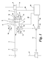
- a drive is schematically illustrated according to a first embodiment of the present invention.
- an internal-combustion engine 1 (or a crankshaft of the internal-combustion engine) is propulsively connected to the input shaft 3 of a power branched planetary transmission 4 by means of a clutch 2.
- the planetary transmission 4 is constructed in the form of a planetary gear-box and splits the power which is delivered via the input shaft 3 into a hydrostatic and into a mechanical power branch.
- a first output shaft 5 of the planetary transmission 4 directly drives a differential gear 6 of a rear axle H of the utility vehicle and thereby forms the mechanical power branch.
- a second output shaft 7 of the planetary transmission 4 drives an adjustable hydraulic pump 10 via a gear wheel stage 8, 9 and thereby forms the hydrostatic power branch.
- the hydraulic pump 10 in turn drives two parallel switched hydraulic motors 11, 12 via (not illustrated) hydraulic lines.
- the hydraulic motors 11, 12 in the case of this embodiment are formed as adjustable hydraulic motors in each case.
- the hydraulic motors 11, 12 comprise output shafts 13, 14 aligned flush with one another in each case.
- the output shaft 13 of the hydraulic motor 11 drives the first output shaft 5 of the planetary transmission 4 and thus the differential gear 6 of the rear axle H of the utility vehicle via a gear wheel stage 15, 16.
- the output shaft 14 of the hydraulic motor 12 drives the power train 17 leading to the front axle V via a gear wheel stage 18, 19. Both output shafts 13, 14 can be coupled together by means of a clutch 20.
- the hydraulic pump 10 is adjusted as a function of the power demand, which the driver sets by corresponding movement of the accelerator pedal and/or a driving speed lever. Furthermore, driving states of the vehicle, such as for example standstill of the vehicle with the engine running, reverse and forward gear, can be adjusted and changed in a simple manner by regulating the hydraulic pump.
- the hydraulic motors 11, 12 are regulated via a (not illustrated) control unit.
- the clutch 20 comprising a number of interleaved clutch plates clamped together by a hydraulic pressure, is adjustable with regard to its torque transmission capacity.
- a reduction in the hydraulic clamping pressure reduces the grip therebetween and introduces a degree of slippage.
- the greater the slippage the lesser the torque transmitted by the clutch 20.
- the hydraulic clamping pressure can be varied between a level at which the clutch 20 is fully engaged with no slippage and a level at which the clutch 20 is fully disengaged with no torque transmitted.
- a control unit 30 which via sensors 32, 34 detects a driving state of the vehicle.
- the sensors 32 and 34 via signal wires 36, 38 are connected to the control unit 30 and convey data thereto concerning the driving state of the vehicle.
- the sensor 32 detects the rotational speed of the output shaft 5 of the planetary transmission 4. From this in turn the rotational speed of the rear axle H can be determined.
- the sensor 34 detects the rotational speed of the gear wheel 19. From this in turn the rotational speed of the front axle V can be determined.
- a control line 40 leads from the control unit 30 to the clutch 20.
- the control unit 30 can actuate the clutch 20 in such a manner that the clutch 20 is fully disengaged, fully engaged, or however transmits a certain torque or a certain amount of the applied torque.
- the control unit 30 actuates the clutch 20 in such a manner that its torque transmission capacity is adjusted as a function of a driving state of the vehicle, which is detected in the present embodiment by the sensors 32 and 34.
- the control unit 30 in this case carries out one or more regulating steps, which are indicated above.
- the driving states explained below result as a function of the degree of engagement or disengagement.
- both vehicle axles H and V can be driven temporarily at constant rotational speed ratio and up to 100% of the possible transmission output torque can be transmitted via an axle H or V.
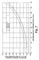
- Fig. 2 With the solid line the optimum rotational speed ratio of a steerable vehicle axle to a non-steerable vehicle axle of a utility vehicle is plotted over the steering angle of the steerable vehicle axle. This optimum rotational speed ratio is reached if the vehicle rounds a bend with the respective steering angle and with no slip developing on the wheels of the vehicle. This optimum rotational speed ratio is called the ideal value below.
- the ideal value is indicated as 1.0 for a steering angle of 0°, that is to say, when travelling straight ahead.
- This ideal value of 1.0 is applicable to such vehicles, wherein the diameters of the front wheels and the rear wheels are the same. If the diameters of the front wheels and the rear wheels are different, the rotational speed ratio must be adapted accordingly.
- the wheels of a steerable vehicle axle cover a larger distance than the wheels of the non-steerable vehicle axle.
- the front axle V is designed as a steerable vehicle axle. Accordingly the ideal value for the rotational speed ratio increments with an increasing steering angle of the steerable vehicle axle, as illustrated by the solid line in the diagram of Fig. 2 .
- the progression of an upper limit value for the rotational speed ratio is drawn as a broken line and the progression of a lower limit value of the rotational speed ratio is drawn as a dash-dotted line.
- the curve for the upper limit value in this case continuously runs above the curve for the optimum rotational speed ratio.
- the upward gradient of the curve corresponds to a large extent to the upward gradient for the optimum rotational speed ratio.
- the distance between the curve of the upper limit value and the curve of the optimum rotational speed ratio in the vertical direction amounts to approximately 0.05.
- the curve for the lower limit value continuously runs below the curve for the optimum rotational speed ratio. In the present case the curve for the lower limit value runs constantly at approximately 0.95.
- Data tables corresponding to such a diagram can be stored for example in a memory of the control unit 30.
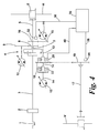
- a disconnection clutch 21 is additionally provided in the power train 17 of the front axle V.
- the front axle V can be disconnected from the drive by the hydraulic motor 12. If the clutch 20 is partly or fully engaged, the front axle V by disengaging the disconnection clutch 21 is additionally disconnected from the drive by the hydraulic motor 11 and from the mechanical branch of the planetary transmission 4.
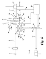
- a further switchable clutch 22 is provided on the output shaft 14 of the hydraulic motor 12 in relation to the first embodiment illustrated in Fig. 1 .
- the hydraulic motor 12 is designed accordingly as a de-connectable hydraulic motor.
- this further clutch 22 can be disengaged and engaged independently from the position of the clutch 20.
- a propulsive connection can be selectively made and broken between the front axle V and the rear axle H.
- the further clutch 22 is also actuated by the control unit 30.
- the hydraulic motor 11 can be propulsively connected via the clutch 20 and the gear wheel stage 18, 19 to the power train 17 of the front axle V.
- the de-connectable hydraulic motor 12 is not propulsively connected via the further clutch 22 to the gear wheel stage 18, 19 but connected to a separately formed gear wheel stage 23, 24.
- the gear wheel stage 23, 24 in this case has a large translation, so that high torque can be transferred from the hydraulic motor 12 to the front axle V.
- high torque can be transmitted to the front axle V by the de-connectable hydraulic motor 12 in particular at low driving speeds.
- the de-connectable hydraulic motor 12 is preferably disconnected from the power train 17 by the further clutch 22.
- the present invention is not limited to the exemplary embodiments illustrated in the figures.
- different motors such as for example electric motors
- the drive power, delivered by an internal-combustion engine 1 in this case can be branched off at a planetary transmission 4, wherein a generator, which is provided in place of the hydraulic pump 10, can be driven by a branched part of the drive power.
- the electric energy produced by the generator in turn can be fed to the two electric motors, which are provided in place of the hydraulic motors 11 and 12.
- the at least two electric motors, which are provided in place of the hydraulic motors 11 and 12 can also be directly fed with electric energy, which is supplied by a battery or a fuel cell, etc.
- the steering angle of a steerable vehicle axle, the total transmitted torque of the drive system, the driving speed of the vehicle, the rotational speeds of the wheels and/or of the vehicle axles and the slip on at least one of the wheels of the vehicle are defined as driving state parameters.
- the control unit 30 can actuate the clutch 20 as a function of one or more of these parameters mentioned.
- the torque transmission capacity of the clutch can be controlled by further parameters of the driving state in addition to or alternatively to the parameters mentioned above.
- sensors 32 and 34 by which the rotational speeds of the front axle and the rear axle can be determined, are illustrated.
- further sensors for example for detecting the total transmitted torque, the driving speed of the vehicle, the steering angle of a steerable vehicle axle or the slip on one or more of the wheels of the vehicle, can also be provided.
Landscapes
- Engineering & Computer Science (AREA)
- Mechanical Engineering (AREA)
- Chemical & Material Sciences (AREA)
- Combustion & Propulsion (AREA)
- Transportation (AREA)
- General Engineering & Computer Science (AREA)
- Arrangement And Driving Of Transmission Devices (AREA)
- Arrangement And Mounting Of Devices That Control Transmission Of Motive Force (AREA)
Applications Claiming Priority (1)
| Application Number | Priority Date | Filing Date | Title |
|---|---|---|---|
| DE102007021732A DE102007021732A1 (de) | 2007-05-09 | 2007-05-09 | Antriebssystem für Fahrzeuge mit mindestens zwei antreibbaren Fahrzeugachsen |
Publications (3)
| Publication Number | Publication Date |
|---|---|
| EP1990230A2 true EP1990230A2 (de) | 2008-11-12 |
| EP1990230A3 EP1990230A3 (de) | 2009-01-28 |
| EP1990230B1 EP1990230B1 (de) | 2013-07-10 |
Family
ID=39709102
Family Applications (1)
| Application Number | Title | Priority Date | Filing Date |
|---|---|---|---|
| EP08008404.9A Active EP1990230B1 (de) | 2007-05-09 | 2008-05-05 | Antriebssystem für Fahrzeuge mit mindestens zwei antreibbaren Fahrzeugachsen |
Country Status (3)
| Country | Link |
|---|---|
| US (1) | US8281890B2 (de) |
| EP (1) | EP1990230B1 (de) |
| DE (1) | DE102007021732A1 (de) |
Cited By (6)
| Publication number | Priority date | Publication date | Assignee | Title |
|---|---|---|---|---|
| WO2011027212A1 (en) * | 2009-09-04 | 2011-03-10 | Agco Gmbh | Tractors |
| EP2743115A4 (de) * | 2011-08-10 | 2015-09-23 | Honda Motor Co Ltd | Vorrichtung zur antriebskraftsteuerung für ein fahrzeug mit allradantrieb |
| EP3626502A1 (de) * | 2018-09-18 | 2020-03-25 | CLAAS Tractor S.A.S. | Antriebsstrang für ein landwirtschaftliches fahrzeug |
| WO2022157572A1 (en) | 2021-01-19 | 2022-07-28 | Agco International Gmbh | Trailer brake control system |
| WO2023031216A1 (de) * | 2021-08-31 | 2023-03-09 | Zf Friedrichshafen Ag | Achsantrieb eines einen vorderachsantrieb und einen hinterachsantrieb aufweisenden fahrzeugs |
| WO2023100004A1 (en) | 2021-12-03 | 2023-06-08 | Agco International Gmbh | Mobile machine and method |
Families Citing this family (17)
| Publication number | Priority date | Publication date | Assignee | Title |
|---|---|---|---|---|
| US8158833B2 (en) * | 2008-12-17 | 2012-04-17 | Bp Biofuels Uk Ltd. | Process, plant and butanol from lignocellulosic feedstock |
| DE102012211021B4 (de) * | 2012-06-27 | 2025-01-30 | Zf Friedrichshafen Ag | Verfahren zum Betreiben eines Getriebes und Getriebesteuerungseinrichtung |
| WO2014018503A1 (en) * | 2012-07-25 | 2014-01-30 | Fisker Automotive, Inc. | All wheel drive system for hybrid vehicle |
| GB201223536D0 (en) | 2012-12-21 | 2013-02-13 | Agco Int Gmbh | Agricultural vehicle transmission |
| US9103425B2 (en) * | 2013-08-26 | 2015-08-11 | Caterpillar Inc. | Cost configurable hystat drive system |
| DE102013224383A1 (de) | 2013-11-28 | 2015-05-28 | Zf Friedrichshafen Ag | Leistungsverzweigter Achsantrieb für Arbeitsmaschinen |
| US9579975B2 (en) | 2014-05-05 | 2017-02-28 | Arvinmeritor Technology, Llc | System and method of controlling a drive axle system |
| US9605756B1 (en) * | 2015-12-08 | 2017-03-28 | Caterpillar Inc. | Hybrid hydrostatic-direct drive transmission |
| DE102016218159A1 (de) | 2016-09-21 | 2018-03-22 | Zf Friedrichshafen Ag | Antriebsanordnung mit einer leistungsverzweigten Getriebevorrichtung |
| DE102018104230B4 (de) * | 2017-03-29 | 2019-08-29 | Christian Hilpert | Verfahren zum Antrieb eines Fahrzeugs mit einer Antriebsanordnung |
| DE102017118858A1 (de) * | 2017-08-18 | 2019-02-21 | Claas Selbstfahrende Erntemaschinen Gmbh | Antriebsstrang zum Antreiben eines Arbeitsaggregates einer selbstfahrenden Erntemaschine |
| US11174926B2 (en) * | 2018-11-29 | 2021-11-16 | Deere & Company | Vehicle transmission |
| DE102021209229A1 (de) | 2021-08-23 | 2023-02-23 | Zf Friedrichshafen Ag | Antriebsvorrichtung für einen Fahrantrieb einer Arbeitsmaschine |
| EP4516554A3 (de) | 2022-01-19 | 2025-05-07 | Deere & Company | Leistungsverzweigter achsantrieb und landwirtschaftliches fahrzeug |
| EP4215392B1 (de) | 2022-01-19 | 2024-09-25 | Deere & Company | Leistungsverzweigter achsantrieb und landwirtschaftliches fahrzeug |
| DE102022101166A1 (de) | 2022-01-19 | 2023-07-20 | Deere & Company | Leistungsverzweigter Achsantrieb und landwirtschaftliches Fahrzeug |
| DE102024102491A1 (de) | 2024-01-29 | 2025-07-31 | Deere & Company | Leistungsverzweigter Achsantrieb, landwirtschaftliches Zugfahrzeug und Verfahren zum Betreiben eines leistungsverzweigten Achsantriebs |
Citations (2)
| Publication number | Priority date | Publication date | Assignee | Title |
|---|---|---|---|---|
| DE4209950C2 (de) | 1992-03-27 | 1994-08-25 | Fendt Xaver Gmbh & Co | Antrieb für zweiachsige land- und/oder bauwirtschaftlich nutzbare Fahrzeuge |
| EP1364824A2 (de) | 2002-05-20 | 2003-11-26 | Deere & Company | Steuervorrichtung für ein Zwischenachs-Differentialgetriebe |
Family Cites Families (8)
| Publication number | Priority date | Publication date | Assignee | Title |
|---|---|---|---|---|
| DE4121629A1 (de) * | 1991-06-29 | 1993-01-14 | Walterscheid Gmbh Jean | Verfahren und antriebsanordnung zur ausuebung des verfahrens zur steuerung der zu- und abschaltung des vierradantriebs eines fahrzeuges, insbesondere eines traktors |
| DE10060679B4 (de) * | 2000-12-06 | 2009-08-13 | Linde Material Handling Gmbh | Hydrostatischer Fahrantrieb |
| JP3642041B2 (ja) * | 2001-06-26 | 2005-04-27 | 日産自動車株式会社 | 4輪駆動車の駆動力制御装置 |
| DE10260196A1 (de) * | 2002-12-20 | 2004-07-01 | Bayerische Motoren Werke Ag | Verfahren zum Steuern einer schaltbaren Kupplung in einem Antriebsstrang eines Kraftfahrzeugs mit Vierradantrieb |
| DE10333650A1 (de) * | 2003-07-24 | 2005-02-24 | Bayerische Motoren Werke Ag | Steuersystem für ein zumindest zeitweise vierradgetriebenes Kraftfahrzeug |
| US6997299B2 (en) * | 2003-07-28 | 2006-02-14 | Magna Powertrain, Inc. | Hydraulic clutch actuation system |
| JP3998016B2 (ja) * | 2004-11-12 | 2007-10-24 | トヨタ自動車株式会社 | 車両用駆動装置 |
| DE102007021733B4 (de) * | 2007-05-09 | 2011-03-10 | Agco Gmbh | Antriebsanordnung für Fahrzeuge mit mindestens zwei antreibbaren Fahrzeugachsen |
-
2007
- 2007-05-09 DE DE102007021732A patent/DE102007021732A1/de not_active Ceased
-
2008
- 2008-05-05 EP EP08008404.9A patent/EP1990230B1/de active Active
- 2008-05-07 US US12/116,809 patent/US8281890B2/en active Active
Patent Citations (2)
| Publication number | Priority date | Publication date | Assignee | Title |
|---|---|---|---|---|
| DE4209950C2 (de) | 1992-03-27 | 1994-08-25 | Fendt Xaver Gmbh & Co | Antrieb für zweiachsige land- und/oder bauwirtschaftlich nutzbare Fahrzeuge |
| EP1364824A2 (de) | 2002-05-20 | 2003-11-26 | Deere & Company | Steuervorrichtung für ein Zwischenachs-Differentialgetriebe |
Cited By (14)
| Publication number | Priority date | Publication date | Assignee | Title |
|---|---|---|---|---|
| WO2011027212A1 (en) * | 2009-09-04 | 2011-03-10 | Agco Gmbh | Tractors |
| EP2743115A4 (de) * | 2011-08-10 | 2015-09-23 | Honda Motor Co Ltd | Vorrichtung zur antriebskraftsteuerung für ein fahrzeug mit allradantrieb |
| US9389616B2 (en) | 2011-08-10 | 2016-07-12 | Honda Motor Co., Ltd. | Driving force control device for four-wheel-drive vehicle |
| EP3626502A1 (de) * | 2018-09-18 | 2020-03-25 | CLAAS Tractor S.A.S. | Antriebsstrang für ein landwirtschaftliches fahrzeug |
| WO2022157572A1 (en) | 2021-01-19 | 2022-07-28 | Agco International Gmbh | Trailer brake control system |
| WO2022157576A1 (en) | 2021-01-19 | 2022-07-28 | Agco International Gmbh | Trailer brake control system |
| WO2022157571A1 (en) | 2021-01-19 | 2022-07-28 | Agco International Gmbh | Trailer brake control system |
| WO2022157574A1 (en) | 2021-01-19 | 2022-07-28 | Agco International Gmbh | Trailer brake control system |
| WO2022157573A1 (en) | 2021-01-19 | 2022-07-28 | Agco International Gmbh | Trailer brake control system |
| WO2022157577A1 (en) | 2021-01-19 | 2022-07-28 | Agco International Gmbh | Trailer brake control system |
| WO2022157575A1 (en) | 2021-01-19 | 2022-07-28 | Agco International Gmbh | Trailer brake control system |
| WO2022157578A1 (en) | 2021-01-19 | 2022-07-28 | Agco International Gmbh | Trailer brake control system |
| WO2023031216A1 (de) * | 2021-08-31 | 2023-03-09 | Zf Friedrichshafen Ag | Achsantrieb eines einen vorderachsantrieb und einen hinterachsantrieb aufweisenden fahrzeugs |
| WO2023100004A1 (en) | 2021-12-03 | 2023-06-08 | Agco International Gmbh | Mobile machine and method |
Also Published As
| Publication number | Publication date |
|---|---|
| EP1990230B1 (de) | 2013-07-10 |
| US8281890B2 (en) | 2012-10-09 |
| US20080277182A1 (en) | 2008-11-13 |
| EP1990230A3 (de) | 2009-01-28 |
| DE102007021732A1 (de) | 2008-11-20 |
Similar Documents
| Publication | Publication Date | Title |
|---|---|---|
| EP1990230B1 (de) | Antriebssystem für Fahrzeuge mit mindestens zwei antreibbaren Fahrzeugachsen | |
| EP1990229B1 (de) | Antriebsanordnung für Fahrzeuge mit mindestens zwei antreibbaren Fahrzeugachsen | |
| US8452504B2 (en) | Control system and method for automatic control of selection of on-demand all-wheel drive assembly for a vehicle drivetrain | |
| EP2401188B1 (de) | Rückwärtsantriebsachse mit direktantrieb | |
| US8900086B2 (en) | Hydraulic vehicle clutch system, drivetrain for a vehicle including same, and method | |
| US8639419B2 (en) | Agricultural vehicle with a continuously variable transmission | |
| CN102844591B (zh) | 集成的传动装置和辅助变速箱控制装置 | |
| US9598068B2 (en) | Control system for four-wheel-drive vehicle | |
| US7779953B2 (en) | Biasing drive torque to an axle in a motor vehicle | |
| US7125358B2 (en) | Distributor transmission having at least three shafts | |
| EP3720760B1 (de) | Bremsung eines nutzfahrzeugs | |
| US10661800B2 (en) | Agricultural vehicle driveline | |
| US8478496B2 (en) | Transmission synchronisation method and device for at least two transmissions | |
| US11834095B2 (en) | Utility vehicle braking | |
| US20040216557A1 (en) | Power split transmission with at least two input shafts | |
| CN112879554A (zh) | 一种单钢轮压路机的起步换挡控制方法、系统及存储介质 | |
| US20090093333A1 (en) | Axle assembly with electro-hydraulic clutch control system | |
| JP2536497B2 (ja) | 4輪駆動型車両用無段変速機の制御装置 | |
| JPS62275840A (ja) | 自動車用自動変速機の動力分配装置 | |
| US20180202548A1 (en) | Vehicle drive train and method for operating a drive train | |
| JPH0692156A (ja) | 4輪駆動車のトルク伝達量制御装置 | |
| EP4572967A1 (de) | Fahrzeug mit steuerbarer kupplung zwischen vorder- und hinterachse und verfahren zur steuerung des variablen kupplungseinrückverhältnisses der kupplung | |
| JP2000142163A (ja) | 車両の動力配分装置 | |
| Деркачев et al. | USE THE TRANSFER BOX WITH AUTOMATIC CONNECTION OF THE FRONT AXLE | |
| JPH0737211B2 (ja) | 4輪駆動車用動力伝達装置 |
Legal Events
| Date | Code | Title | Description |
|---|---|---|---|
| PUAI | Public reference made under article 153(3) epc to a published international application that has entered the european phase |
Free format text: ORIGINAL CODE: 0009012 |
|
| AK | Designated contracting states |
Kind code of ref document: A2 Designated state(s): AT BE BG CH CY CZ DE DK EE ES FI FR GB GR HR HU IE IS IT LI LT LU LV MC MT NL NO PL PT RO SE SI SK TR |
|
| AX | Request for extension of the european patent |
Extension state: AL BA MK RS |
|
| PUAL | Search report despatched |
Free format text: ORIGINAL CODE: 0009013 |
|
| AK | Designated contracting states |
Kind code of ref document: A3 Designated state(s): AT BE BG CH CY CZ DE DK EE ES FI FR GB GR HR HU IE IS IT LI LT LU LV MC MT NL NO PL PT RO SE SI SK TR |
|
| AX | Request for extension of the european patent |
Extension state: AL BA MK RS |
|
| 17P | Request for examination filed |
Effective date: 20090728 |
|
| AKX | Designation fees paid |
Designated state(s): DE FR GB IT |
|
| 17Q | First examination report despatched |
Effective date: 20090907 |
|
| GRAP | Despatch of communication of intention to grant a patent |
Free format text: ORIGINAL CODE: EPIDOSNIGR1 |
|
| GRAS | Grant fee paid |
Free format text: ORIGINAL CODE: EPIDOSNIGR3 |
|
| GRAA | (expected) grant |
Free format text: ORIGINAL CODE: 0009210 |
|
| AK | Designated contracting states |
Kind code of ref document: B1 Designated state(s): DE FR GB IT |
|
| REG | Reference to a national code |
Ref country code: GB Ref legal event code: FG4D |
|
| REG | Reference to a national code |
Ref country code: DE Ref legal event code: R096 Ref document number: 602008025861 Country of ref document: DE Effective date: 20130905 |
|
| PLBE | No opposition filed within time limit |
Free format text: ORIGINAL CODE: 0009261 |
|
| STAA | Information on the status of an ep patent application or granted ep patent |
Free format text: STATUS: NO OPPOSITION FILED WITHIN TIME LIMIT |
|
| 26N | No opposition filed |
Effective date: 20140411 |
|
| REG | Reference to a national code |
Ref country code: DE Ref legal event code: R097 Ref document number: 602008025861 Country of ref document: DE Effective date: 20140411 |
|
| REG | Reference to a national code |
Ref country code: FR Ref legal event code: PLFP Year of fee payment: 9 |
|
| REG | Reference to a national code |
Ref country code: FR Ref legal event code: PLFP Year of fee payment: 10 |
|
| REG | Reference to a national code |
Ref country code: FR Ref legal event code: PLFP Year of fee payment: 11 |
|
| PGFP | Annual fee paid to national office [announced via postgrant information from national office to epo] |
Ref country code: SE Payment date: 20180529 Year of fee payment: 14 |
|
| PGFP | Annual fee paid to national office [announced via postgrant information from national office to epo] |
Ref country code: GB Payment date: 20180518 Year of fee payment: 11 |
|
| GBPC | Gb: european patent ceased through non-payment of renewal fee |
Effective date: 20190505 |
|
| PG25 | Lapsed in a contracting state [announced via postgrant information from national office to epo] |
Ref country code: GB Free format text: LAPSE BECAUSE OF NON-PAYMENT OF DUE FEES Effective date: 20190505 Ref country code: IT Free format text: LAPSE BECAUSE OF NON-PAYMENT OF DUE FEES Effective date: 20190505 |
|
| REG | Reference to a national code |
Ref country code: DE Ref legal event code: R084 Ref document number: 602008025861 Country of ref document: DE |
|
| PGFP | Annual fee paid to national office [announced via postgrant information from national office to epo] |
Ref country code: FR Payment date: 20220523 Year of fee payment: 15 |
|
| P01 | Opt-out of the competence of the unified patent court (upc) registered |
Effective date: 20230518 |
|
| PG25 | Lapsed in a contracting state [announced via postgrant information from national office to epo] |
Ref country code: FR Free format text: LAPSE BECAUSE OF NON-PAYMENT OF DUE FEES Effective date: 20230531 |
|
| PGFP | Annual fee paid to national office [announced via postgrant information from national office to epo] |
Ref country code: DE Payment date: 20250521 Year of fee payment: 18 |