EP1990277A2 - Station pour encapsuler des produits avec un boîtier tubulaire - Google Patents
Station pour encapsuler des produits avec un boîtier tubulaire Download PDFInfo
- Publication number
- EP1990277A2 EP1990277A2 EP08007891A EP08007891A EP1990277A2 EP 1990277 A2 EP1990277 A2 EP 1990277A2 EP 08007891 A EP08007891 A EP 08007891A EP 08007891 A EP08007891 A EP 08007891A EP 1990277 A2 EP1990277 A2 EP 1990277A2
- Authority
- EP
- European Patent Office
- Prior art keywords
- casing
- zone
- grippers
- capping
- station according
- Prior art date
- Legal status (The legal status is an assumption and is not a legal conclusion. Google has not performed a legal analysis and makes no representation as to the accuracy of the status listed.)
- Withdrawn
Links
- 238000009825 accumulation Methods 0.000 claims abstract description 24
- 238000007664 blowing Methods 0.000 claims abstract description 11
- 230000007306 turnover Effects 0.000 claims description 2
- 239000002985 plastic film Substances 0.000 description 8
- 229920006255 plastic film Polymers 0.000 description 8
- 238000004806 packaging method and process Methods 0.000 description 3
- 238000012856 packing Methods 0.000 description 3
- 238000003780 insertion Methods 0.000 description 2
- 230000037431 insertion Effects 0.000 description 2
- 230000005540 biological transmission Effects 0.000 description 1
- 230000000903 blocking effect Effects 0.000 description 1
- 239000011449 brick Substances 0.000 description 1
- 239000004566 building material Substances 0.000 description 1
- 230000003247 decreasing effect Effects 0.000 description 1
- 230000000916 dilatatory effect Effects 0.000 description 1
- 239000004033 plastic Substances 0.000 description 1
- 238000004804 winding Methods 0.000 description 1
Images


Classifications
-
- B—PERFORMING OPERATIONS; TRANSPORTING
- B65—CONVEYING; PACKING; STORING; HANDLING THIN OR FILAMENTARY MATERIAL
- B65B—MACHINES, APPARATUS OR DEVICES FOR, OR METHODS OF, PACKAGING ARTICLES OR MATERIALS; UNPACKING
- B65B7/00—Closing containers or receptacles after filling
- B65B7/16—Closing semi-rigid or rigid containers or receptacles not deformed by, or not taking-up shape of, contents, e.g. boxes or cartons
- B65B7/28—Closing semi-rigid or rigid containers or receptacles not deformed by, or not taking-up shape of, contents, e.g. boxes or cartons by applying separate preformed closures, e.g. lids, covers
-
- B—PERFORMING OPERATIONS; TRANSPORTING
- B65—CONVEYING; PACKING; STORING; HANDLING THIN OR FILAMENTARY MATERIAL
- B65B—MACHINES, APPARATUS OR DEVICES FOR, OR METHODS OF, PACKAGING ARTICLES OR MATERIALS; UNPACKING
- B65B11/00—Wrapping, e.g. partially or wholly enclosing, articles or quantities of material, in strips, sheets or blanks, of flexible material
- B65B11/58—Applying two or more wrappers, e.g. in succession
- B65B11/585—Applying two or more wrappers, e.g. in succession to stacked articles, e.g. pallettised loads
Definitions
- This invention relates to a station for capping articles by means of a tubular casing made of plastic film, especially for capping articles stacked in an orderly manner on pallets.
- a general object of this invention is to obviate the above-mentioned drawbacks by supplying a capping station for products, especially stacked on pallets, by means of a tubular casing of plastic film, that allow rapid, efficient and reliable capping.
- a further object of the invention is to provide a capping station of relatively reduced overall dimensions.
- a station for capping an article set in a capping zone by means of a flexible tubular casing comprising means of gripping the outside of the casing that are mobile to grip an edge of the end of the casing fed to them and they are equipped with means of traction and curling the wall of the casing starting from this end edge to accommodate the curly part in a zone of accumulation within the gripping means.
- the gripping means being moreover mobile to insert the casing on the article in the capping zone gradually releasing the curled portion in the zone of accumulation, characterized in that the gripping means comprise blowing means to form a cushion of air between a sliding wall of the zone of accumulation and the curled portion of the casing to help unwind the casing from the zone of accumulation during capping.
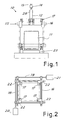
- FIG 1 there is schematically shown a station, indicated generally with 10, for capping articles 11 with a tubular casing of plastic film 12.
- the article to package can be composed of a stack of items set orderly on a pallet to form a parallelepiped.
- the tube of plastic film is of a relatively elastic known type to allow its elastic expansion by traction during the packaging of the product and better adhesion to the walls of the product after release.
- the film could be of an elasto-plastic type.
- the item to be packed might not have the shape of a parallelepiped, still being able to be packaged all the same by using very elastic film.
- the traction of the film during packaging can be conducted both vertically and horizontally (radially).
- the tubular casing can be obtained from a continuous pipe 13 fed to the machine (for instance, in a flattened condition) and joined and cut crossways by known means of joining and cutting 14, so as to obtain a sack-shaped cap facing downward to hang above the zone for receiving the product to package.
- a capping unit 15 is made sliding vertically with motorized control to move between a high position (shown with a solid line in figure 1 ) for receiving the casing and a low position (shown with a dotted line) for complete capping of the product.
- the unit 15 advantageously has a frame structure 16 to surround the zone for receiving the product so as to slide along the side walls of the product.
- the unit includes means 17 for gripping the outside of the casing and curling it starting from the lower edge of the end to accumulate the wall of the casing inside a zone of accumulation in these means.
- the gripping means are in the form of four grippers that each comes near an edge of a rectangle (as shown again in figure 2 ).
- the gripping means 17 are mobile to turn over the curled casing on them and then to unroll it on the article to cap, so as to bring it back "straight.”
- the grippers have therefore initially the mouth facing upward to grip the lower edge of the hanging casing, while they have the mouth facing downward while they slide along the vertical walls of the product being packaged.
- the station can include a horizontal conveyor 23 (for instance, a conveyor belt, rollers or similar) that transits in the capping zone of the station to bring an article 11 in and out of this zone.
- a horizontal conveyor 23 for instance, a conveyor belt, rollers or similar
- the gripping and curling means are mobile to pull and dilate the casing toward the outside before putting it on the article.
- the frame 16 advantageously includes motorized controlled means of moving the grippers to move the grippers horizontally so as to form a rectangle of pre-arranged dimensions.
- the solid line shows the near position of the grippers to receive the edge of the casing as it arrives from the feeder.
- the dotted line instead shows the grippers in the far position after curling and stretching the film, ready to begin the phase of turning over and moving down.
- guiding means or positioning grippers 28 can be included at the corners of the casing to aid an initial opening of the tubular casing so as to position its mouth correctly on the vertical of the four grippers.
- the frame is advantageously formed with four guides, arranged according to the sides of a rectangle and with a motorized system of symmetrical movement away and near for each pair of parallel guides.
- the system of motorization can advantageously include a male-female screw transmission 18, 19 moved by a corresponding motor 20, 21.
- the grippers are directed on the plane so as to grip each casing on a different side of the rectangle near to a different edge.
- the grippers are in any case shown simply as a pair of grippers facing each other.
- the horizontal movement of the grippers permits dilating the casing stretching the elastic film so as to bring it to a greater size than that of the product to package and allow its easy insertion.
- the real extent of the movement will depend on the dimensions of the product to package.
- the machine can in this way receive and treat articles of different size.
- FIG. 3 shows two grippers 17 in the near position in greater detail.
- Each gripper that can be opened is advantageously equipped with a fixed jaw 24 and a mobile jaw 25 to control opening and closing by an appropriate actuator (not shown).
- the gripper also includes motorized means to pull the casing toward the inside of the gripper and to curl it between the jaws in a zone of accumulation 30, made sufficiently long.
- These motorized means advantageously include a motorized roller 26 near the gripping end of the gripper on the fixed jaw.
- An idle counter-roller 27 is correspondingly present on the end of the mobile jaw.
- the gripping means 17 are provided with blowing means 40 in correspondence with the zone of accumulation 30, suited to create a cushion of air between the wall of the casing 12 collected in the zone of accumulation 30 and a wall 41 of the zone of accumulation, so as in the capping phase to aid the release of the casing from the gripper 17.
- the blowing means are, preferably, made with a plurality of nozzles 40 arranged on the sliding face 41, formed on the jaw 24 that, as will be seen, keeps the tubular film dilated under tension during capping.
- Figure 3 shows the first phase of a capping cycle, with the grippers open and near and the casing 12 not yet dilated and held by positioning grippers 28 to insert its mouth in the grippers.
- the grippers close and the motorized means curl the casing in the zone of accumulation of the grippers, as shown in figure 4 .
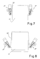
- the grippers are made to turn opposite to each other around the axis 29 to tip over downwards so as to overturn the casing ( figures 5 and 6 ).
- the grippers can be moved appropriately outwards to avoid reciprocal interference.
- the casing 12 is kept gripped by keeping the motorized rollers stationary.
- the bag of the casing keeps the join facing upward but the grippers are above the bag.
- the motorized winding wheel goes inside the perimeter of the bag and the pressing roller outside.
- the four grippers are made to move away symmetrically ( figure 6 ) to stretch the four sides of the tubular casing uniformly to a sufficient size to put it on the product that has reached the capping zone.
- the motorized roller inside facilitates the following operation of stretching while keeping the film firmly blocked.
- the capping unit After reaching the correct expansion, the capping unit begins to come down onto the pack gradually unrolling the curled casing between the grippers ( figure 7 ). In this phase the blowing means 40 are operated, so as to help the casing unroll as the grippers come down.
- Figure 9 shows an enlargement of a gripper 17 with the operated blowing means 40.
- the emission of air by the nozzles 40 forms a cushion of air that makes the wall of the casing 12 move away from the sliding wall 41 in the zone of accumulation 30. This makes it possible to have optimal film unrolling, decreasing friction and, as a result, the risk of the casing getting broken or stuck.
- the nozzles 40 on the wall 41 are advantageously spaced apart in a regular manner to reduce the friction uniformly all over the jaw 24 that keeps the film under tension as it unwinds.
- the blowing air could be fed to the nozzles 40 through a special hose (not shown in the figure) that feeds a circuit inside the gripper 17.
- the capping unit 15 can raise up again and the packaged product can be evacuated from the station, with the contracted film firmly blocking it.
- the unrolling of the film on the package is more uniform and the grippers can even reach the base of the package without any need for them to have a gap under the base level of the package. This allows having a reduced height of the station and using a conveyor with no need for vertical lifters.
- the positioning means and the exact structure of the grippers can vary according to specific requirements.
- the grippers can also be directly set on the diagonals of the rectangle.
- the grippers need not even be able to be overturned, but move along the product to be capped always maintaining the same orientation in relation to the article to cap.
- the blowing means of the gripper need not necessarily be made with a plurality of nozzles, as described above.
- to produce the desired cushion of air straight channels could be obtained on the sliding wall of the gripper, or holes that can form a manifold.
Landscapes
- Engineering & Computer Science (AREA)
- Mechanical Engineering (AREA)
- Basic Packing Technique (AREA)
- Apparatus For Disinfection Or Sterilisation (AREA)
- Devices For Medical Bathing And Washing (AREA)
Applications Claiming Priority (1)
| Application Number | Priority Date | Filing Date | Title |
|---|---|---|---|
| IT000905A ITMI20070905A1 (it) | 2007-05-07 | 2007-05-07 | "stazione di incappucciamento di prodotti mediante un involucro tubolare" |
Publications (1)
| Publication Number | Publication Date |
|---|---|
| EP1990277A2 true EP1990277A2 (fr) | 2008-11-12 |
Family
ID=39683594
Family Applications (1)
| Application Number | Title | Priority Date | Filing Date |
|---|---|---|---|
| EP08007891A Withdrawn EP1990277A2 (fr) | 2007-05-07 | 2008-04-24 | Station pour encapsuler des produits avec un boîtier tubulaire |
Country Status (2)
| Country | Link |
|---|---|
| EP (1) | EP1990277A2 (fr) |
| IT (1) | ITMI20070905A1 (fr) |
Cited By (2)
| Publication number | Priority date | Publication date | Assignee | Title |
|---|---|---|---|---|
| ITUB20159526A1 (it) * | 2015-12-18 | 2017-06-18 | Messersi Packaging Srl | Macchina incappucciatrice |
| EP4631869A1 (fr) | 2024-04-10 | 2025-10-15 | Officina Meccanica Sestese S.p.A. | Appareil de hissage cumulatif et méthode de hissage relative |
-
2007
- 2007-05-07 IT IT000905A patent/ITMI20070905A1/it unknown
-
2008
- 2008-04-24 EP EP08007891A patent/EP1990277A2/fr not_active Withdrawn
Cited By (2)
| Publication number | Priority date | Publication date | Assignee | Title |
|---|---|---|---|---|
| ITUB20159526A1 (it) * | 2015-12-18 | 2017-06-18 | Messersi Packaging Srl | Macchina incappucciatrice |
| EP4631869A1 (fr) | 2024-04-10 | 2025-10-15 | Officina Meccanica Sestese S.p.A. | Appareil de hissage cumulatif et méthode de hissage relative |
Also Published As
| Publication number | Publication date |
|---|---|
| ITMI20070905A1 (it) | 2008-11-08 |
Similar Documents
| Publication | Publication Date | Title |
|---|---|---|
| US10703518B2 (en) | Wrapping machine | |
| EP3105124B1 (fr) | Appareil d'emballage utilisant un film d'étirement comportant un dispositif de retenue amélioré | |
| CN105492327B (zh) | 用可伸缩膜包裹物品的冷加工收缩包裹机及相关方法 | |
| CN107848642A (zh) | 包装机 | |
| US8117806B2 (en) | Vertical bagging machine | |
| US7937910B2 (en) | Method and machine for preparing and depositing a stretch-film packaging sleeve on a palletized load | |
| EP3215421B2 (fr) | Système d'emballage par enveloppement agencé horizontalement | |
| CN111094134B (zh) | 包装系统和包装物体的方法 | |
| CN109415174B (zh) | 用于包装产品的机器和方法 | |
| EP1990277A2 (fr) | Station pour encapsuler des produits avec un boîtier tubulaire | |
| FI111530B (fi) | Menetelmä ja laite pakkauksen varustamiseksi päällyskalvolla käärintäpakkauskoneessa | |
| GB1274038A (en) | Device for mounting flexible tube heat shrinkable material over stacked articles | |
| EP1762493B1 (fr) | Procédé et installation pour disposer une gaine tubulaire sur un objet | |
| JP4358047B2 (ja) | 包装装置 | |
| EP2431279B1 (fr) | Machine pour appliquer une housse d'emballage sur un objet | |
| JP2707187B2 (ja) | 食品を収容した被包装体のフィルム包装方法及びその装置 | |
| JPH0616212U (ja) | フィルム包装装置 | |
| JPH06345053A (ja) | フィルム袋の拡げ方法 | |
| JPH0542004Y2 (fr) | ||
| CN119032048A (zh) | 包裹机器和包裹方法 | |
| JPH0558981B2 (fr) | ||
| JP2707194B2 (ja) | 包装装置 | |
| JPH09301314A (ja) | 胴巻き装置 | |
| GB2405133A (en) | Packaging delicate items in tubular wrapping |
Legal Events
| Date | Code | Title | Description |
|---|---|---|---|
| PUAI | Public reference made under article 153(3) epc to a published international application that has entered the european phase |
Free format text: ORIGINAL CODE: 0009012 |
|
| AK | Designated contracting states |
Kind code of ref document: A2 Designated state(s): AT BE BG CH CY CZ DE DK EE ES FI FR GB GR HR HU IE IS IT LI LT LU LV MC MT NL NO PL PT RO SE SI SK TR |
|
| AX | Request for extension of the european patent |
Extension state: AL BA MK RS |
|
| STAA | Information on the status of an ep patent application or granted ep patent |
Free format text: STATUS: THE APPLICATION IS DEEMED TO BE WITHDRAWN |
|
| 18D | Application deemed to be withdrawn |
Effective date: 20121101 |