EP1990292B1 - Element support d'un outil a bords - Google Patents
Element support d'un outil a bords Download PDFInfo
- Publication number
- EP1990292B1 EP1990292B1 EP07714955A EP07714955A EP1990292B1 EP 1990292 B1 EP1990292 B1 EP 1990292B1 EP 07714955 A EP07714955 A EP 07714955A EP 07714955 A EP07714955 A EP 07714955A EP 1990292 B1 EP1990292 B1 EP 1990292B1
- Authority
- EP
- European Patent Office
- Prior art keywords
- sheet
- opening
- support member
- edged tool
- scissors
- Prior art date
- Legal status (The legal status is an assumption and is not a legal conclusion. Google has not performed a legal analysis and makes no representation as to the accuracy of the status listed.)
- Not-in-force
Links
- 230000002093 peripheral effect Effects 0.000 claims abstract description 17
- 230000008878 coupling Effects 0.000 claims description 39
- 238000010168 coupling process Methods 0.000 claims description 39
- 238000005859 coupling reaction Methods 0.000 claims description 39
- 210000002105 tongue Anatomy 0.000 claims description 37
- 230000004308 accommodation Effects 0.000 claims description 17
- 230000001747 exhibiting effect Effects 0.000 claims description 10
- 230000037431 insertion Effects 0.000 claims description 8
- 238000003780 insertion Methods 0.000 claims description 8
- 238000000926 separation method Methods 0.000 abstract 1
- 101100008049 Caenorhabditis elegans cut-5 gene Proteins 0.000 description 4
- 101100008050 Caenorhabditis elegans cut-6 gene Proteins 0.000 description 4
- 238000005516 engineering process Methods 0.000 description 3
- 239000000725 suspension Substances 0.000 description 3
- 239000000463 material Substances 0.000 description 2
- 229920003023 plastic Polymers 0.000 description 2
- 208000019300 CLIPPERS Diseases 0.000 description 1
- 208000021930 chronic lymphocytic inflammation with pontine perivascular enhancement responsive to steroids Diseases 0.000 description 1
Images


Classifications
-
- B—PERFORMING OPERATIONS; TRANSPORTING
- B26—HAND CUTTING TOOLS; CUTTING; SEVERING
- B26B—HAND-HELD CUTTING TOOLS NOT OTHERWISE PROVIDED FOR
- B26B29/00—Guards or sheaths or guides for hand cutting tools; Arrangements for guiding hand cutting tools
- B26B29/04—Guards or sheaths for scissors, e.g. combined with manicuring appliances
-
- A—HUMAN NECESSITIES
- A47—FURNITURE; DOMESTIC ARTICLES OR APPLIANCES; COFFEE MILLS; SPICE MILLS; SUCTION CLEANERS IN GENERAL
- A47F—SPECIAL FURNITURE, FITTINGS, OR ACCESSORIES FOR SHOPS, STOREHOUSES, BARS, RESTAURANTS OR THE LIKE; PAYING COUNTERS
- A47F5/00—Show stands, hangers, or shelves characterised by their constructional features
- A47F5/0006—Hangers for hanging articles on bars, tringles, bracket arms or the like
-
- A—HUMAN NECESSITIES
- A47—FURNITURE; DOMESTIC ARTICLES OR APPLIANCES; COFFEE MILLS; SPICE MILLS; SUCTION CLEANERS IN GENERAL
- A47F—SPECIAL FURNITURE, FITTINGS, OR ACCESSORIES FOR SHOPS, STOREHOUSES, BARS, RESTAURANTS OR THE LIKE; PAYING COUNTERS
- A47F7/00—Show stands, hangers, or shelves, adapted for particular articles or materials
- A47F7/0021—Show stands, hangers, or shelves, adapted for particular articles or materials for long or non-stable articles, e.g. fishing rods, pencils, lipsticks or the like; Compartments or recesses as stabilising means
- A47F7/0028—Show stands, hangers, or shelves, adapted for particular articles or materials for long or non-stable articles, e.g. fishing rods, pencils, lipsticks or the like; Compartments or recesses as stabilising means with one compartment or recess for each article
-
- B—PERFORMING OPERATIONS; TRANSPORTING
- B65—CONVEYING; PACKING; STORING; HANDLING THIN OR FILAMENTARY MATERIAL
- B65D—CONTAINERS FOR STORAGE OR TRANSPORT OF ARTICLES OR MATERIALS, e.g. BAGS, BARRELS, BOTTLES, BOXES, CANS, CARTONS, CRATES, DRUMS, JARS, TANKS, HOPPERS, FORWARDING CONTAINERS; ACCESSORIES, CLOSURES, OR FITTINGS THEREFOR; PACKAGING ELEMENTS; PACKAGES
- B65D73/00—Packages comprising articles attached to cards, sheets or webs
- B65D73/0007—Packages comprising articles attached to cards, sheets or webs the articles being attached to the plane surface of a single card
- B65D73/0014—Packages comprising articles attached to cards, sheets or webs the articles being attached to the plane surface of a single card by means of separate fixing elements, e.g. clips, clamps, bands
Definitions
- the present invention relates to a support member used in exhibiting edged tools such as scissors.
- Patent Document 1 discloses a technology in which a bridge part, a retaining cord, or a retaining sheet is used to support western scissors on a mounting sheet, in such a manner that the scissors can be opened and closed. In this instance, the cutting edges of the scissors on the mounting sheet may be touched inadvertently.
- Patent Document 2 Japanese Laid-Open Utility Model Publication No. 5-35743
- Patent Document 2 Japanese Laid-Open Patent Publication No. 2005-187004
- An objective of the present invention is to provide a support member for exhibiting an edged tool which is capable of preventing sheets constituting a support body from being separated from each other.
- a support member used in exhibiting an edged tool having a cutting edge and a handle.
- the support member is provided with a support body and retaining means.
- the support body is formed by a first sheet and a second sheet being superimposed on each other so as to form an accommodation chamber between the first sheet and the second sheet.
- the second sheet is provided inside of the outer peripheral edges with an opening which allows the cutting edge of the edged tool to be inserted.
- the cutting edge of the edged tool which has been inserted into the opening is accommodated in the accommodation chamber so as to be covered with the first sheet and the second sheet.
- the handle of the edged tool of which the cutting edge has been accommodated in the accommodation chamber is arranged so as to be superimposed on the second sheet.
- the retaining means supports on the support body the edged tool, the cutting edge of which has been accommodated in the accommodation chamber. According to this configuration, since the second sheet is pressed against the first sheet by the handle of the edged tool, the cutting edge of which has been accommodated in the accommodation chamber, it is possible to prevent the second sheet from being separated from the first sheet.
- the support body is formed by coupling the separately formed first and second sheets to each other by coupling means.
- the first sheet and the second sheet can be formed of different materials.
- the coupling means includes a pair of first coupling portions and a pair of second coupling portions.
- first coupling portions are located in front in the insertion direction from the second coupling portions.
- the first coupling portions are arranged on both sides of the cutting edge which has been inserted into the opening.
- Each of the first coupling portions includes a cut disposed on one of the first sheet and the second sheet and a tongue disposed on the other of the first sheet and the second sheet and inserted into the cut.
- Each of the cuts and each of the tongues are respectively provided with a locking portion.
- the first sheet or the second sheet is deformed so that the tongues are inserted into the cuts, and thereafter, with the tongues inserted into the cuts, the locking portions of the tongues are locked at the locking portions of the cuts, thereby preventing the tongues from being removed from the cuts.
- an interval between the locking portions of the cuts is made smaller than an interval between the locking portions of the tongues, by which the first sheet or the second sheet is deflected and deformed between the first coupling portions so that the accommodation chamber is formed between the first sheet and the second sheet.
- the second coupling portions are disposed between the opening and the handle of the edged tool and also closer to the opening than to the handle. In this instance, the second sheet is prevented more reliably from being separated from the first sheet.
- the cutting edge of the edged tool accommodated in the accommodation chamber is visible from outside of the first sheet through the first sheet or from outside of the second sheet through the second sheet.
- the edged tool is preferably a pair of scissors.
- the retaining means includes an inner peripheral edge of the opening, and the inner peripheral edge acts so as to lock the opening/closing pivot of scissors.
- the opening/closing pivot of the scissors can be used to support the scissors on the support body.
- the retaining means includes a retaining hole disposed on the first sheet for locking the opening/closing pivot of scissors.
- the opening/closing pivot of the scissors can be used to support the scissors on the support body.
- the retaining means includes a binding band for bonding the handle of scissors to the support body.
- the binding band can be used to support the scissors on the support body more reliably.
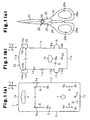
- a mounting sheet 1 as a first sheet shown in Fig. 1(a) is formed of an opaque cardboard in a shape longer in the vertical direction Z (the up and down direction in Figs. 1(a) and 1(b) ).
- the mounting sheet 1 is composed of a front face 2 and a back face 3 (refer to Fig. 2(b) ) enclosed by the outer peripheral edges including an upper edge 1a, a lower edge 1b, a left edge 1c, and a right edge 1d.
- a suspension hole 4 is formed so as to open both in the front face 2 and the back face 3 at a position that is slightly below the upper edge 1a and in the center in the lateral direction Y (the left and right direction shown in Figs.
- Streak-like first cuts 5, 6 are formed so as to open both in the front face 2 and the back face 3 at positions slightly inside from the left edge 1c and the right edge 1d on both left and right sides below the suspension hole 4.
- a circular retaining hole 7 is formed so as to open both in the front face 2 and the back face 3 at the center of the lower half part of the mounting sheet 1 in the lateral direction Y.
- Streak-like second cuts 8, 9 are formed so as to open both in the front face 2 and the back face 3 at positions slightly inside from the left edge 1c and the right edge 1d on both left and right sides slightly below the retaining hole 7.
- a pair of band holes 10 are formed so as to open both in the front face 2 and the back face 3 below the retaining hole 7 and also between both cuts 8, 9.
- a covering sheet 11 as a second sheet is formed of a transparent plastic plate in a shape longer in the vertical direction Z.
- the covering sheet 11 is composed of a front face 12 and a back face 13 (refer to Fig. 2(c) ) enclosed by the outer peripheral edges including an upper edge 11a, a lower edge 11b, a left edge 11c, and a right edge 11d.
- First tongues 14, 15 extend respectively from the left edge 11c and the right edge 11d at positions slightly below the upper edge 11a at the upper half part of the covering sheet 11.
- An opening 16 is formed so as to open both in the front face 12 and the back face 13 at the center of the lower half part of the covering sheet 11 in the lateral direction Y.
- Second tongues 17, 18 extend respectively from the left edge 11c and the right edge 11d at positions slightly below the opening 16.
- a pair of band holes 19 are formed so as to open both in the front face 12 and the back face 13 below the opening 16 and also between both the tongues 17, 18.
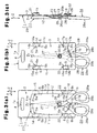
- the mounting sheet 1 and the covering sheet 11, which are formed separately, are superimposed on each other in a state in which the front face 2 of the mounting sheet 1 is made to face the back face 13 of the covering sheet 11 as shown in Figs. 2(a) to 2(c) , thereby forming a support body 20.
- the first tongues 14, 15 of the upper half part of the covering sheet 11 are inserted into the first cuts 5, 6 of the upper half part of the mounting sheet 1 and the second tongues 17, 18 of the lower half part of the covering sheet 11 are inserted into the second cuts 8, 9 of the lower half part of the mounting sheet 1.
- the first cut 5 and the first tongue 14 as well as the first cut 6 and the first tongue 15 constitute respectively the first coupling portions 21.
- the second cut 8 and the second tongue 17 as well as the second cut 9 and the second tongue 18 respectively constitute the second coupling portions 22.
- the first coupling portions 21 and the second coupling portions 22 constitute coupling means (couplers) for coupling the mounting sheet 1 to the covering sheet 11.
- Locking portions 8a, 8b are formed respectively at the upper end and the lower end of the second cut 8, and locking portions 9a, 9b are formed respectively at the upper end and the lower end of the second cut 9.
- Locking portions 17a, 17b are formed respectively at the upper end and the lower end of the second tongue 17, and locking portions 18a, 18b are formed respectively at the upper end and the lower end of the second tongue 18.
- the locking portions 17a, 17b of the second tongue 17 lock respectively with the locking portions 8a, 8b of the second cut 8, and the locking portions 18a, 18b of the second tongue 18 lock respectively with the locking portions 9a, 9b of the second cut 9, by which the covering sheet 11 is positioned with respect to the mounting sheet 1 so as not to move along the vertical direction Z.
- Locking portion 5a, 5b are formed respectively at the upper end and the lower end of the first cut 5, and locking portions 6a, 6b are formed respectively at the upper end and the lower end of the first cut 6.
- the L-shaped first tongue 14 is provided with a locking arm portion 14a extending upward along the left edge 11c
- the L-shaped first tongue 15 is provided with a locking arm portion 15a extending upward along the right edge 11d.
- a locking groove portion 14b as a locking portion is disposed between the locking arm portion 14a and the left edge 11c
- a locking groove portion 15b as a locking portion is disposed between the locking arm portion 15a and the right edge 11d.
- An interval A (refer to Fig.
- the locking portions 5a, 6a of the cuts 5, 6 are locked into the locking groove portions 14b, 15b of the covering sheet 11, thereby preventing the tongues 14, 15 from being removed from the cuts 5, 6.
- the covering sheet 11 is deflected and deformed between the first coupling portions 21, thereby forming an accommodation chamber 23 between the mounting sheet 1 and the covering sheet 11.
- a pair of western scissors 24 as an edged tool shown in Fig. 1(c) are provided with a pair of scissor pieces 25 supported by an opening/closing pivot 26 so as to move rotationally.
- Each of the scissor pieces 25 is provided with a cutting edge 27 formed at the distal end from the opening/closing pivot 26 and a handle 28 formed at the proximal end from the opening/closing pivot 26.
- Each of the handles 28 is provided with a grip ring 28a.
- a contact part actually touched by the fingers in gripping the edged tool with a hand is an inner peripheral part 28b of the grip ring 28a in the case of the western scissors 24.
- the opening/closing pivot 26 is provided with a bolt 26a and a nut 26b. The bolt 26a and the nut 26b are projected from the main faces of the scissor pieces 25.
- the cutting edges 27 of the scissors 24 are inserted into the opening 16 from the front face 12 of the covering sheet 11. Then, as shown in Figs. 3(a) to 3(c) , the cutting edges 27 are accommodated in the accommodation chamber 23 between the mounting sheet 1 and the covering sheet 11 so as to be covered by the mounting sheet 1 and the covering sheet 11.
- the upper half parts of the handles 28 of the scissors 24 are located on the front face 12 of the covering sheet 11, while the lower half parts of the handles 28, more specifically, parts of the grip rings 28a, are located below the lower edge 1b of the mounting sheet 1.
- a binding band 29 is made to pass through the band hole 10 on the mounting sheet 1 and the band hole 19 on the covering sheet 11, and one of the handles 28 of the scissors 24 is bonded to the support body 20 by using the binding band 29.
- the retaining hole 7, the inner peripheral edge 16a of the opening 16, and the binding band 29 constitute retaining means (a retainer) for supporting the scissors 24 on the support body 20.
- the second coupling portions 22 are located between a plane orthogonal to the vertical direction Z and also passing through the inner peripheral edge 16a of the opening 16 and a plane orthogonal to the vertical direction Z and also passing through the inner peripheral parts 28b of the grip rings 28a of the handles 28 of the scissors 24 in a closed state.
- the second coupling portions 22 are located between the opening 16 and the inner peripheral parts 28b (contact parts) of the grip rings 28a. Further, the second coupling portions 22 are located closer to the opening 16 rather than to the inner peripheral parts 28b of the grip rings 28a.
- the second coupling portions 22 are located in front in the insertion direction from an intermediate point between the inner peripheral parts 28b of the grip rings 28a and the opening 16.
- the support member for supporting the scissors 24 is exhibited, while being suspended by the suspension hole 4.
- the cutting edges 27 of the thus exhibited scissors 24 are visible through the transparent covering sheet 11. Further, the handles 28 of the scissors 24 can be directly touched to open and close the handles 28.
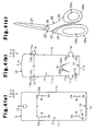
- Figs. 4(a) to 5(c) show a support member for exhibiting an edged tool according to a second embodiment of the present invention.
- Figs. 4(a) to 5(c) correspond respectively to Figs. 1(a) to 1(c) and 3(a) to 3(c).
- the support member for exhibiting an edged tool of the second embodiment is different from that of the first embodiment in the following points.
- the retaining hole 7 on the mounting sheet 1 is omitted.
- the opening/closing pivot 26 of the scissors 24 is not projected from the main faces of the scissor pieces 25, but is substantially flush with the main faces of the scissor pieces 25.
- a tongue 30b is formed on the opening 16 by a reverse U-shaped cut 30a formed on the covering sheet 11.
- Locking groove portions 18a, 18b are formed at the base part of the right tongue 18 of the tongues 17, 18 on the covering sheet 11.
- the locking groove portions 18a, 18b are respectively locked by the locking portions 9a, 9b disposed on the right cut 9 of the cuts 8, 9 on the mounting sheet 1, thereby the tongue 18 is prevented from being removed from the cut 9 inadvertently.
- the present invention may also be applicable to a support member used in exhibiting scissors other than western scissors, for example, grip scissors, and edged tools other than scissors, for example, kitchen knives, knives, medical scalpels, razors, nail clippers, and peelers.
- the covering sheet 11 may be formed of transparent plastics.
- the lower edge of the covering sheet 11 may be adhered to the lower edge of the mounting sheet 1.
- a sheet may folded to form integrally the mounting sheet and the covering sheet.
- the lower edge of the mounting sheet may be joined to the lower edge of the covering sheet.
- the left edge of the mounting sheet may be joined to the left edge of the covering sheet.
- the right edge of the mounting sheet may be joined to the right edge of the covering sheet.
- the interval A between the locking portion 5a of the first cut 5 and the locking portion 6a of the first cut 6 may be made larger than the interval B between the locking groove portion 14b of the first tongue 14 and locking groove portion 15b of the first tongue 15, by which the mounting sheet 1 is deflected and deformed between the first coupling portions 21 so that the accommodation chamber 23 is formed between the mounting sheet 1 and the covering sheet 11.
- the entire handles 28 may be located above the front face 12 of the covering sheet 11.
- the mounting sheet 1 and the covering sheet 11 may be changed in material, shape, or dimension, whenever necessary.
- Product information may be printed on the mounting sheet 1 and the covering sheet 11.
Landscapes
- Engineering & Computer Science (AREA)
- Mechanical Engineering (AREA)
- Life Sciences & Earth Sciences (AREA)
- Forests & Forestry (AREA)
- Scissors And Nippers (AREA)
- Packages (AREA)
- Knives (AREA)
- Packaging Of Annular Or Rod-Shaped Articles, Wearing Apparel, Cassettes, Or The Like (AREA)
Abstract
Claims (7)
- Élément de support utilisé pour présenter un outil tranchant (24) comprenant un bord tranchant (27) et une poignée (28), l'élément de support comprenant un corps de support (20) formé par une première feuille (1) et une seconde feuille (11) superposées l'une sur l'autre de sorte qu'une chambre de logement (23) soit formée entre la première feuille et la seconde feuille, dans lequel la seconde feuille est pourvue, à l'intérieur de bords périphériques extérieurs (11a, 11b, 11c, 11d), d'une ouverture (16) qui permet au bord tranchant de l'outil tranchant d'être inséré, le bord tranchant de l'outil tranchant inséré dans l'ouverture est logé dans la chambre de logement de sorte à être recouvert par la première feuille et la seconde feuille, la poignée de l'outil tranchant dont le bord tranchant a été logé dans la chambre de logement est agencée de sorte à être superposée sur la seconde feuille,
l'élément de support étant caractérisé en ce qu'il comprend des moyens de retenue (7, 16a, 29) pour supporter, sur le corps de support, l'outil tranchant, dont le bord tranchant a été logé dans la chambre de logement,
et en ce que le corps de support est formé en raccordant les première et seconde feuilles formées séparément l'une avec l'autre par l'intermédiaire de moyens de raccordement (21, 22), lesdits moyens de raccordement comprenant une paire de premières portions de raccordement (21) et une paire de secondes portions de raccordement (22),
dans lequel, lorsqu'une direction dans laquelle le bord tranchant de l'outil tranchant est inséré dans l'ouverture est appelée direction d'insertion (ZU), les premières portions de raccordement sont positionnées à l'avant dans la direction d'insertion à partir des secondes portions de raccordement,
dans lequel les premières portions de raccordement sont agencées sur les deux côtés du bord tranchant qui est inséré dans l'ouverture,
dans lequel chacune des premières portions de raccordement comprend une découpe (5, 6) disposée sur l'une parmi la première feuille et la seconde feuille et une languette (14, 15) disposée sur l'autre feuille et insérée dans la découpe, chacune des découpes et chacune des languettes sont respectivement pourvues d'une portion de verrouillage (5a, 5b, 6a, 6b, 14b, 15b), lorsque chacune des languettes est insérée dans la découpe correspondante, la portion de verrouillage (14b, 15b) de la languette se verrouille dans la portion de verrouillage (5a, 5b, 6a, 6b) de la découpe, empêchant ainsi la languette d'être retirée de la découpe, et
dans lequel un intervalle (A) entre les portions de verrouillage des découpes est plus petit qu'un intervalle (B) entre les portions de verrouillage des languettes, ainsi la première feuille ou la seconde feuille est défléchie et déformée entre les premières portions de raccordement de sorte que la chambre de logement soit formée entre la première feuille et la seconde feuille. - Élément de support selon la revendication 1, caractérisé en ce que les secondes portions de raccordement sont disposées entre l'ouverture et la poignée de l'outil tranchant et également disposées plus près de l'ouverture que de la poignée.
- Élément de support selon la revendication 1 ou 2, caractérisé en ce que le bord tranchant de l'outil tranchant logé dans la chambre de logement est visible à partir de l'extérieur de la première feuille à travers la première feuille ou à partir de l'extérieur de la seconde feuille à travers la seconde feuille.
- Élément de support selon une quelconque des revendications 1 à 3, caractérisé en ce que l'outil tranchant est une paire de ciseaux (24).
- Élément de support selon la revendication 4, caractérisé en ce que les moyens de retenue comprennent un bord périphérique intérieur (16a) de l'ouverture, et le bord périphérique intérieur agit de sorte à verrouiller le pivot d'ouverture/de fermeture (26) des ciseaux.
- Élément de support selon la revendication 4 ou 5, caractérisé en ce que les moyens de retenue comprennent un trou de retenue (7) disposé sur la première feuille pour verrouiller le pivot d'ouverture/de fermeture (26) des ciseaux.
- Élément de support selon une quelconque des revendications 4 à 6, caractérisé en ce que les moyens de retenue comprennent une bande de liaison (29) pour lier les poignées des ciseaux au corps de support.
Applications Claiming Priority (2)
| Application Number | Priority Date | Filing Date | Title |
|---|---|---|---|
| JP2006053244A JP4837397B2 (ja) | 2006-02-28 | 2006-02-28 | 刃物陳列用支持部材 |
| PCT/JP2007/053562 WO2007099923A1 (fr) | 2006-02-28 | 2007-02-27 | Element support d'un outil a bords |
Publications (3)
| Publication Number | Publication Date |
|---|---|
| EP1990292A1 EP1990292A1 (fr) | 2008-11-12 |
| EP1990292A4 EP1990292A4 (fr) | 2009-12-23 |
| EP1990292B1 true EP1990292B1 (fr) | 2012-07-18 |
Family
ID=38459029
Family Applications (1)
| Application Number | Title | Priority Date | Filing Date |
|---|---|---|---|
| EP07714955A Not-in-force EP1990292B1 (fr) | 2006-02-28 | 2007-02-27 | Element support d'un outil a bords |
Country Status (4)
| Country | Link |
|---|---|
| US (1) | US20090065386A1 (fr) |
| EP (1) | EP1990292B1 (fr) |
| JP (1) | JP4837397B2 (fr) |
| WO (1) | WO2007099923A1 (fr) |
Families Citing this family (15)
| Publication number | Priority date | Publication date | Assignee | Title |
|---|---|---|---|---|
| US7789234B2 (en) * | 2007-02-08 | 2010-09-07 | Wayne Clark | Display package for scissors |
| US10160126B2 (en) * | 2009-12-16 | 2018-12-25 | Laura Ranieri | Protective sheath for securing a blade of a cutlery implement |
| US8322531B2 (en) | 2010-05-05 | 2012-12-04 | Stanley Black & Decker, Inc. | Twin blade knife package |
| KR101487280B1 (ko) * | 2013-12-07 | 2015-01-28 | 박수형 | 수동공구 노출포장 케이스 |
| KR101478481B1 (ko) * | 2014-01-20 | 2014-12-31 | 이랄라 | 방수팩용 포장케이스 |
| US9480347B2 (en) * | 2014-08-28 | 2016-11-01 | B&G Plastics, Inc. | Jewelry display hanger with cable tie |
| US10220995B2 (en) * | 2015-01-07 | 2019-03-05 | Westrock Mwv, Llc | Blister card with flange strap |
| US20160303731A1 (en) * | 2015-04-14 | 2016-10-20 | James Edwin Barlow | Hand Tool and Retainer |
| EP3288729B1 (fr) * | 2015-04-30 | 2019-06-26 | Husqvarna AB | Dispositif de coupe sous emballage |
| US11203476B2 (en) * | 2018-11-02 | 2021-12-21 | Westrock Mwv, Llc | Product package, display card, clip and blank therefor |
| GB2583554A (en) * | 2019-04-30 | 2020-11-04 | Monument Tools Ltd | Pipe cutter |
| US11717371B2 (en) * | 2020-02-03 | 2023-08-08 | SterileBits, Inc. | Instrument protector backer card |
| FI3981705T3 (fi) * | 2020-10-06 | 2024-06-28 | Husqvarna Ab | Pakkaus leikkaustyökalua varten |
| EP4169850A1 (fr) * | 2021-10-20 | 2023-04-26 | Husqvarna Ab | Emballage pour outil de coupe |
| US20230211942A1 (en) * | 2021-12-30 | 2023-07-06 | RMX Industries | Weather resistant plastic packaging |
Family Cites Families (16)
| Publication number | Priority date | Publication date | Assignee | Title |
|---|---|---|---|---|
| JPS5119276Y2 (fr) * | 1972-10-11 | 1976-05-20 | ||
| JPS4988363A (fr) * | 1972-12-28 | 1974-08-23 | ||
| JPS52114984U (fr) * | 1976-02-26 | 1977-08-31 | ||
| US4165805A (en) * | 1978-06-01 | 1979-08-28 | Fiskars Manufacturing Corporation | Blister packages for scissors, pliers and other hand tools |
| US4179029A (en) * | 1978-06-01 | 1979-12-18 | Fiskars Manufacturing Corporation | Functional blister package for snipper-type scissors |
| FI72480C (sv) * | 1985-08-29 | 1987-06-08 | Fiskars Ab Oy | Förpackning för saxar. |
| US5279417A (en) * | 1992-07-14 | 1994-01-18 | Fiskars Oy Ab | Package for hand tools |
| US5291996A (en) * | 1993-01-15 | 1994-03-08 | Fiskars Oy Ab | Reusable display sheath with frangible latch means |
| JPH0685269U (ja) * | 1993-05-19 | 1994-12-06 | 協永産業株式会社 | 商品の包装体 |
| US5435447A (en) * | 1994-02-22 | 1995-07-25 | Acme United Corporation | Product holding and displaying member |
| US5477964A (en) * | 1994-12-27 | 1995-12-26 | The Stanley Works | Package for an elongated tool |
| US20020100704A1 (en) * | 2001-01-26 | 2002-08-01 | Hp Intellectual Corp. | Mounting and display card for hand operated tool |
| US6854184B2 (en) * | 2002-02-26 | 2005-02-15 | Ek Success, Ltd. | Blade cover for cutting device |
| JP4399247B2 (ja) * | 2003-12-25 | 2010-01-13 | 株式会社貝印刃物開発センター | 鋏陳列用支持部材 |
| US20060113205A1 (en) * | 2004-12-01 | 2006-06-01 | Cheng-Chih Liu | Display package |
| US7789234B2 (en) * | 2007-02-08 | 2010-09-07 | Wayne Clark | Display package for scissors |
-
2006
- 2006-02-28 JP JP2006053244A patent/JP4837397B2/ja not_active Expired - Fee Related
-
2007
- 2007-02-27 EP EP07714955A patent/EP1990292B1/fr not_active Not-in-force
- 2007-02-27 US US12/224,493 patent/US20090065386A1/en not_active Abandoned
- 2007-02-27 WO PCT/JP2007/053562 patent/WO2007099923A1/fr not_active Ceased
Also Published As
| Publication number | Publication date |
|---|---|
| US20090065386A1 (en) | 2009-03-12 |
| JP4837397B2 (ja) | 2011-12-14 |
| EP1990292A4 (fr) | 2009-12-23 |
| EP1990292A1 (fr) | 2008-11-12 |
| JP2007230594A (ja) | 2007-09-13 |
| WO2007099923A1 (fr) | 2007-09-07 |
Similar Documents
| Publication | Publication Date | Title |
|---|---|---|
| EP1990292B1 (fr) | Element support d'un outil a bords | |
| US11577412B2 (en) | Utility knife | |
| EP1888305B1 (fr) | Dispositif de decoupage de support | |
| EP2701884B1 (fr) | Protection pour lame de scie circulaire | |
| USD464851S1 (en) | Egg slicer | |
| USD1023717S1 (en) | Multi-tool knife | |
| US12528217B2 (en) | Cutter tool | |
| USD460334S1 (en) | Combined box cutter and scissors | |
| USD523701S1 (en) | Sandwich holder | |
| US7100794B2 (en) | Paper container | |
| JP5698073B2 (ja) | 包装媒体収納容器 | |
| USD525390S1 (en) | Straight razor | |
| USD558553S1 (en) | Cutting tool | |
| US20020041789A1 (en) | Binders with inside and outside pockets and methods for constructing same | |
| JP2018117863A (ja) | 納豆パックカッター | |
| USD461384S1 (en) | Scissors | |
| WO2024116423A1 (fr) | Rasoir | |
| WO2004041487A1 (fr) | Ouvre boite pour emballage de vinyle | |
| JP2017149459A (ja) | チャック付き袋 | |
| EP3746374B1 (fr) | Ensemble d'emballage d'outil de coupe | |
| JP3142448U (ja) | 包装箱 | |
| JP2002029191A (ja) | ホルダー | |
| USD528396S1 (en) | Blade opener for a folding knife | |
| EP3981705A1 (fr) | Emballage pour outil de coupe | |
| JP4975988B2 (ja) | ラップフィルム巻物収納箱 |
Legal Events
| Date | Code | Title | Description |
|---|---|---|---|
| PUAI | Public reference made under article 153(3) epc to a published international application that has entered the european phase |
Free format text: ORIGINAL CODE: 0009012 |
|
| 17P | Request for examination filed |
Effective date: 20080911 |
|
| AK | Designated contracting states |
Kind code of ref document: A1 Designated state(s): DE FR GB |
|
| DAX | Request for extension of the european patent (deleted) | ||
| RBV | Designated contracting states (corrected) |
Designated state(s): DE FR GB |
|
| A4 | Supplementary search report drawn up and despatched |
Effective date: 20091125 |
|
| 17Q | First examination report despatched |
Effective date: 20100308 |
|
| GRAP | Despatch of communication of intention to grant a patent |
Free format text: ORIGINAL CODE: EPIDOSNIGR1 |
|
| GRAS | Grant fee paid |
Free format text: ORIGINAL CODE: EPIDOSNIGR3 |
|
| GRAA | (expected) grant |
Free format text: ORIGINAL CODE: 0009210 |
|
| AK | Designated contracting states |
Kind code of ref document: B1 Designated state(s): DE FR GB |
|
| REG | Reference to a national code |
Ref country code: GB Ref legal event code: FG4D |
|
| REG | Reference to a national code |
Ref country code: DE Ref legal event code: R096 Ref document number: 602007024065 Country of ref document: DE Effective date: 20120913 |
|
| PLBE | No opposition filed within time limit |
Free format text: ORIGINAL CODE: 0009261 |
|
| STAA | Information on the status of an ep patent application or granted ep patent |
Free format text: STATUS: NO OPPOSITION FILED WITHIN TIME LIMIT |
|
| 26N | No opposition filed |
Effective date: 20130419 |
|
| REG | Reference to a national code |
Ref country code: DE Ref legal event code: R097 Ref document number: 602007024065 Country of ref document: DE Effective date: 20130419 |
|
| REG | Reference to a national code |
Ref country code: FR Ref legal event code: PLFP Year of fee payment: 10 |
|
| REG | Reference to a national code |
Ref country code: FR Ref legal event code: PLFP Year of fee payment: 11 |
|
| PGFP | Annual fee paid to national office [announced via postgrant information from national office to epo] |
Ref country code: FR Payment date: 20170105 Year of fee payment: 11 |
|
| PGFP | Annual fee paid to national office [announced via postgrant information from national office to epo] |
Ref country code: GB Payment date: 20170224 Year of fee payment: 11 |
|
| GBPC | Gb: european patent ceased through non-payment of renewal fee |
Effective date: 20180227 |
|
| REG | Reference to a national code |
Ref country code: FR Ref legal event code: ST Effective date: 20181031 |
|
| PG25 | Lapsed in a contracting state [announced via postgrant information from national office to epo] |
Ref country code: GB Free format text: LAPSE BECAUSE OF NON-PAYMENT OF DUE FEES Effective date: 20180227 Ref country code: FR Free format text: LAPSE BECAUSE OF NON-PAYMENT OF DUE FEES Effective date: 20180228 |
|
| PGFP | Annual fee paid to national office [announced via postgrant information from national office to epo] |
Ref country code: DE Payment date: 20200227 Year of fee payment: 14 |
|
| REG | Reference to a national code |
Ref country code: DE Ref legal event code: R119 Ref document number: 602007024065 Country of ref document: DE |
|
| PG25 | Lapsed in a contracting state [announced via postgrant information from national office to epo] |
Ref country code: DE Free format text: LAPSE BECAUSE OF NON-PAYMENT OF DUE FEES Effective date: 20210901 |