EP1990320A2 - Extraction d'ammonium des eaux usées et conversion électrolytique en gaz azote - Google Patents
Extraction d'ammonium des eaux usées et conversion électrolytique en gaz azote Download PDFInfo
- Publication number
- EP1990320A2 EP1990320A2 EP08103930A EP08103930A EP1990320A2 EP 1990320 A2 EP1990320 A2 EP 1990320A2 EP 08103930 A EP08103930 A EP 08103930A EP 08103930 A EP08103930 A EP 08103930A EP 1990320 A2 EP1990320 A2 EP 1990320A2
- Authority
- EP
- European Patent Office
- Prior art keywords
- ammonia
- water
- circuit
- wastewater
- station
- Prior art date
- Legal status (The legal status is an assumption and is not a legal conclusion. Google has not performed a legal analysis and makes no representation as to the accuracy of the status listed.)
- Withdrawn
Links
- 239000002351 wastewater Substances 0.000 title claims abstract description 53
- QGZKDVFQNNGYKY-UHFFFAOYSA-O Ammonium Chemical compound [NH4+] QGZKDVFQNNGYKY-UHFFFAOYSA-O 0.000 title claims abstract description 37
- IJGRMHOSHXDMSA-UHFFFAOYSA-N Atomic nitrogen Chemical compound N#N IJGRMHOSHXDMSA-UHFFFAOYSA-N 0.000 title claims abstract description 19
- 229910001873 dinitrogen Inorganic materials 0.000 title claims description 17
- 238000000605 extraction Methods 0.000 title description 10
- 238000006243 chemical reaction Methods 0.000 title description 4
- QGZKDVFQNNGYKY-UHFFFAOYSA-N Ammonia Chemical compound N QGZKDVFQNNGYKY-UHFFFAOYSA-N 0.000 claims abstract description 246
- XLYOFNOQVPJJNP-UHFFFAOYSA-N water Substances O XLYOFNOQVPJJNP-UHFFFAOYSA-N 0.000 claims abstract description 165
- 229910021529 ammonia Inorganic materials 0.000 claims abstract description 113
- 239000012528 membrane Substances 0.000 claims abstract description 26
- 238000000034 method Methods 0.000 claims abstract description 6
- 239000000463 material Substances 0.000 claims abstract description 5
- 238000012546 transfer Methods 0.000 claims abstract description 4
- HEMHJVSKTPXQMS-UHFFFAOYSA-M Sodium hydroxide Chemical compound [OH-].[Na+] HEMHJVSKTPXQMS-UHFFFAOYSA-M 0.000 claims description 45
- 230000003647 oxidation Effects 0.000 claims description 13
- 238000007254 oxidation reaction Methods 0.000 claims description 13
- XKMRRTOUMJRJIA-UHFFFAOYSA-N ammonia nh3 Chemical compound N.N XKMRRTOUMJRJIA-UHFFFAOYSA-N 0.000 claims description 6
- 230000007423 decrease Effects 0.000 claims description 6
- 238000005342 ion exchange Methods 0.000 claims description 5
- 238000012545 processing Methods 0.000 claims description 5
- 239000012267 brine Substances 0.000 claims description 3
- 239000007789 gas Substances 0.000 claims description 3
- HPALAKNZSZLMCH-UHFFFAOYSA-M sodium;chloride;hydrate Chemical compound O.[Na+].[Cl-] HPALAKNZSZLMCH-UHFFFAOYSA-M 0.000 claims description 3
- 239000007788 liquid Substances 0.000 claims description 2
- 239000000126 substance Substances 0.000 claims 4
- 238000007599 discharging Methods 0.000 claims 3
- 230000001131 transforming effect Effects 0.000 claims 3
- 150000002500 ions Chemical class 0.000 claims 1
- 230000009466 transformation Effects 0.000 claims 1
- 238000004886 process control Methods 0.000 abstract description 12
- 238000011282 treatment Methods 0.000 abstract description 11
- 230000002209 hydrophobic effect Effects 0.000 abstract description 4
- 229910052757 nitrogen Inorganic materials 0.000 abstract 1
- 238000005516 engineering process Methods 0.000 description 13
- 238000005868 electrolysis reaction Methods 0.000 description 10
- 238000011068 loading method Methods 0.000 description 10
- 229910000069 nitrogen hydride Inorganic materials 0.000 description 9
- QGZKDVFQNNGYKY-OUBTZVSYSA-N Ammonia-15N Chemical compound [15NH3] QGZKDVFQNNGYKY-OUBTZVSYSA-N 0.000 description 8
- VEXZGXHMUGYJMC-UHFFFAOYSA-N Hydrochloric acid Chemical compound Cl VEXZGXHMUGYJMC-UHFFFAOYSA-N 0.000 description 7
- 238000005259 measurement Methods 0.000 description 6
- 238000010586 diagram Methods 0.000 description 5
- 230000005611 electricity Effects 0.000 description 5
- 239000002253 acid Substances 0.000 description 4
- 239000010432 diamond Substances 0.000 description 4
- 230000008901 benefit Effects 0.000 description 3
- 238000010924 continuous production Methods 0.000 description 3
- 230000003247 decreasing effect Effects 0.000 description 3
- QWPPOHNGKGFGJK-UHFFFAOYSA-N hypochlorous acid Chemical compound ClO QWPPOHNGKGFGJK-UHFFFAOYSA-N 0.000 description 3
- 230000007935 neutral effect Effects 0.000 description 3
- DGAQECJNVWCQMB-PUAWFVPOSA-M Ilexoside XXIX Chemical compound C[C@@H]1CC[C@@]2(CC[C@@]3(C(=CC[C@H]4[C@]3(CC[C@@H]5[C@@]4(CC[C@@H](C5(C)C)OS(=O)(=O)[O-])C)C)[C@@H]2[C@]1(C)O)C)C(=O)O[C@H]6[C@@H]([C@H]([C@@H]([C@H](O6)CO)O)O)O.[Na+] DGAQECJNVWCQMB-PUAWFVPOSA-M 0.000 description 2
- FAPWRFPIFSIZLT-UHFFFAOYSA-M Sodium chloride Chemical compound [Na+].[Cl-] FAPWRFPIFSIZLT-UHFFFAOYSA-M 0.000 description 2
- 239000003513 alkali Substances 0.000 description 2
- 239000002585 base Substances 0.000 description 2
- 238000010923 batch production Methods 0.000 description 2
- 230000001351 cycling effect Effects 0.000 description 2
- 238000003487 electrochemical reaction Methods 0.000 description 2
- 230000008030 elimination Effects 0.000 description 2
- 238000003379 elimination reaction Methods 0.000 description 2
- 230000000737 periodic effect Effects 0.000 description 2
- -1 polyethylene Polymers 0.000 description 2
- 230000003134 recirculating effect Effects 0.000 description 2
- 230000008929 regeneration Effects 0.000 description 2
- 238000011069 regeneration method Methods 0.000 description 2
- 239000011734 sodium Substances 0.000 description 2
- 229910052708 sodium Inorganic materials 0.000 description 2
- ZAMOUSCENKQFHK-UHFFFAOYSA-N Chlorine atom Chemical compound [Cl] ZAMOUSCENKQFHK-UHFFFAOYSA-N 0.000 description 1
- UFHFLCQGNIYNRP-UHFFFAOYSA-N Hydrogen Chemical compound [H][H] UFHFLCQGNIYNRP-UHFFFAOYSA-N 0.000 description 1
- 239000004698 Polyethylene Substances 0.000 description 1
- 230000002378 acidificating effect Effects 0.000 description 1
- 239000000460 chlorine Substances 0.000 description 1
- 229910052801 chlorine Inorganic materials 0.000 description 1
- 125000004122 cyclic group Chemical group 0.000 description 1
- 230000001419 dependent effect Effects 0.000 description 1
- 230000008021 deposition Effects 0.000 description 1
- 238000011161 development Methods 0.000 description 1
- 230000018109 developmental process Effects 0.000 description 1
- 238000002474 experimental method Methods 0.000 description 1
- 239000004811 fluoropolymer Substances 0.000 description 1
- 229920002313 fluoropolymer Polymers 0.000 description 1
- 238000010438 heat treatment Methods 0.000 description 1
- 238000002156 mixing Methods 0.000 description 1
- 239000000203 mixture Substances 0.000 description 1
- 238000012986 modification Methods 0.000 description 1
- 230000004048 modification Effects 0.000 description 1
- 229920000573 polyethylene Polymers 0.000 description 1
- 230000001172 regenerating effect Effects 0.000 description 1
- 229920006395 saturated elastomer Polymers 0.000 description 1
- 239000011780 sodium chloride Substances 0.000 description 1
- 229910001415 sodium ion Inorganic materials 0.000 description 1
- 239000000243 solution Substances 0.000 description 1
- 238000011269 treatment regimen Methods 0.000 description 1
- 230000001960 triggered effect Effects 0.000 description 1
- 239000002699 waste material Substances 0.000 description 1
Images




Classifications
-
- C—CHEMISTRY; METALLURGY
- C02—TREATMENT OF WATER, WASTE WATER, SEWAGE, OR SLUDGE
- C02F—TREATMENT OF WATER, WASTE WATER, SEWAGE, OR SLUDGE
- C02F9/00—Multistage treatment of water, waste water or sewage
- C02F9/20—Portable or detachable small-scale multistage treatment devices, e.g. point of use or laboratory water purification systems
-
- B—PERFORMING OPERATIONS; TRANSPORTING
- B01—PHYSICAL OR CHEMICAL PROCESSES OR APPARATUS IN GENERAL
- B01D—SEPARATION
- B01D61/00—Processes of separation using semi-permeable membranes, e.g. dialysis, osmosis or ultrafiltration; Apparatus, accessories or auxiliary operations specially adapted therefor
-
- C—CHEMISTRY; METALLURGY
- C02—TREATMENT OF WATER, WASTE WATER, SEWAGE, OR SLUDGE
- C02F—TREATMENT OF WATER, WASTE WATER, SEWAGE, OR SLUDGE
- C02F1/00—Treatment of water, waste water, or sewage
- C02F1/20—Treatment of water, waste water, or sewage by degassing, i.e. liberation of dissolved gases
-
- C—CHEMISTRY; METALLURGY
- C02—TREATMENT OF WATER, WASTE WATER, SEWAGE, OR SLUDGE
- C02F—TREATMENT OF WATER, WASTE WATER, SEWAGE, OR SLUDGE
- C02F1/00—Treatment of water, waste water, or sewage
- C02F1/46—Treatment of water, waste water, or sewage by electrochemical methods
- C02F1/461—Treatment of water, waste water, or sewage by electrochemical methods by electrolysis
- C02F1/46104—Devices therefor; Their operating or servicing
-
- C—CHEMISTRY; METALLURGY
- C02—TREATMENT OF WATER, WASTE WATER, SEWAGE, OR SLUDGE
- C02F—TREATMENT OF WATER, WASTE WATER, SEWAGE, OR SLUDGE
- C02F1/00—Treatment of water, waste water, or sewage
- C02F1/58—Treatment of water, waste water, or sewage by removing specified dissolved compounds
- C02F1/586—Treatment of water, waste water, or sewage by removing specified dissolved compounds by removing ammoniacal nitrogen
-
- C—CHEMISTRY; METALLURGY
- C02—TREATMENT OF WATER, WASTE WATER, SEWAGE, OR SLUDGE
- C02F—TREATMENT OF WATER, WASTE WATER, SEWAGE, OR SLUDGE
- C02F9/00—Multistage treatment of water, waste water or sewage
-
- B—PERFORMING OPERATIONS; TRANSPORTING
- B01—PHYSICAL OR CHEMICAL PROCESSES OR APPARATUS IN GENERAL
- B01D—SEPARATION
- B01D2311/00—Details relating to membrane separation process operations and control
- B01D2311/04—Specific process operations in the feed stream; Feed pretreatment
-
- B—PERFORMING OPERATIONS; TRANSPORTING
- B01—PHYSICAL OR CHEMICAL PROCESSES OR APPARATUS IN GENERAL
- B01D—SEPARATION
- B01D2311/00—Details relating to membrane separation process operations and control
- B01D2311/06—Specific process operations in the permeate stream
-
- C—CHEMISTRY; METALLURGY
- C02—TREATMENT OF WATER, WASTE WATER, SEWAGE, OR SLUDGE
- C02F—TREATMENT OF WATER, WASTE WATER, SEWAGE, OR SLUDGE
- C02F1/00—Treatment of water, waste water, or sewage
- C02F1/26—Treatment of water, waste water, or sewage by extraction
-
- C—CHEMISTRY; METALLURGY
- C02—TREATMENT OF WATER, WASTE WATER, SEWAGE, OR SLUDGE
- C02F—TREATMENT OF WATER, WASTE WATER, SEWAGE, OR SLUDGE
- C02F1/00—Treatment of water, waste water, or sewage
- C02F1/44—Treatment of water, waste water, or sewage by dialysis, osmosis or reverse osmosis
- C02F1/444—Treatment of water, waste water, or sewage by dialysis, osmosis or reverse osmosis by ultrafiltration or microfiltration
-
- C—CHEMISTRY; METALLURGY
- C02—TREATMENT OF WATER, WASTE WATER, SEWAGE, OR SLUDGE
- C02F—TREATMENT OF WATER, WASTE WATER, SEWAGE, OR SLUDGE
- C02F1/00—Treatment of water, waste water, or sewage
- C02F1/46—Treatment of water, waste water, or sewage by electrochemical methods
- C02F1/461—Treatment of water, waste water, or sewage by electrochemical methods by electrolysis
-
- C—CHEMISTRY; METALLURGY
- C02—TREATMENT OF WATER, WASTE WATER, SEWAGE, OR SLUDGE
- C02F—TREATMENT OF WATER, WASTE WATER, SEWAGE, OR SLUDGE
- C02F1/00—Treatment of water, waste water, or sewage
- C02F1/46—Treatment of water, waste water, or sewage by electrochemical methods
- C02F1/461—Treatment of water, waste water, or sewage by electrochemical methods by electrolysis
- C02F1/467—Treatment of water, waste water, or sewage by electrochemical methods by electrolysis by electrochemical disinfection; by electrooxydation or by electroreduction
-
- C—CHEMISTRY; METALLURGY
- C02—TREATMENT OF WATER, WASTE WATER, SEWAGE, OR SLUDGE
- C02F—TREATMENT OF WATER, WASTE WATER, SEWAGE, OR SLUDGE
- C02F1/00—Treatment of water, waste water, or sewage
- C02F1/66—Treatment of water, waste water, or sewage by neutralisation; pH adjustment
-
- C—CHEMISTRY; METALLURGY
- C02—TREATMENT OF WATER, WASTE WATER, SEWAGE, OR SLUDGE
- C02F—TREATMENT OF WATER, WASTE WATER, SEWAGE, OR SLUDGE
- C02F2101/00—Nature of the contaminant
- C02F2101/10—Inorganic compounds
- C02F2101/16—Nitrogen compounds, e.g. ammonia
-
- C—CHEMISTRY; METALLURGY
- C02—TREATMENT OF WATER, WASTE WATER, SEWAGE, OR SLUDGE
- C02F—TREATMENT OF WATER, WASTE WATER, SEWAGE, OR SLUDGE
- C02F2209/00—Controlling or monitoring parameters in water treatment
- C02F2209/005—Processes using a programmable logic controller [PLC]
-
- C—CHEMISTRY; METALLURGY
- C02—TREATMENT OF WATER, WASTE WATER, SEWAGE, OR SLUDGE
- C02F—TREATMENT OF WATER, WASTE WATER, SEWAGE, OR SLUDGE
- C02F2209/00—Controlling or monitoring parameters in water treatment
- C02F2209/02—Temperature
-
- C—CHEMISTRY; METALLURGY
- C02—TREATMENT OF WATER, WASTE WATER, SEWAGE, OR SLUDGE
- C02F—TREATMENT OF WATER, WASTE WATER, SEWAGE, OR SLUDGE
- C02F2209/00—Controlling or monitoring parameters in water treatment
- C02F2209/06—Controlling or monitoring parameters in water treatment pH
Definitions
- ammonia is extracted from wastewater at an ammonia-extraction station.
- the ammonia extracted from the wastewater is transferred into a body of secondary-water.
- the secondary-water is then subjected to electrolysis, done in such manner as to transform the dissolved ammonium directly to nitrogen gas.
- the new ammonia-extraction station makes use of a hydrophobic gas-permeable membrane.
- a hydrophobic gas-permeable membrane allows (gaseous) ammonia, NH3, to pass through the membrane, but is impermeable to water.
- -ammonia- should be understood generically as including ammonia, NH3, in both gaseous and dissolved form, and also as including the ionised form, ammonium, NH4+.
- ammonia-extraction station makes use of the following properties of ammonia in water.
- high pH e.g pH of ten to twelve
- high temperature e.g thirty to sixty degC
- ammonia in water takes the form predominantly of ammonia itself, NH3.
- ammonia in water typically is in the form of a mixture of dissolved ammonia gas and dissolved (ionised) ammonium, NH4+.
- ammonia gas which, being of low solubility in high-pH water, is readily extracted from the water.
- the water is at low pH (e.g a pH of two), nearly all the ammonia is in the form of ionised ammonium.
- the designers' intent is to extract the ammonia from the wastewater, and transfer it into the secondary-water.
- the temperature and pH of the wastewater are raised, whereby ammonia NH3 is the predominant form.
- the high-pH / high-temperature wastewater then passes into a membrane chamber.
- the ammonia NH3 passes through the membrane, but the liquid water does not.
- the secondary-water is of a low pH. Therefore, as the ammonia, NH3, having passed through the membrane, and upon entering the low-pH secondary-water, goes into solution as ionised ammonium, NH4+.
- the secondary-water circulates through the electrolysis station, where the ammonium is oxidised to nitrogen gas.
- one of the benefits of using the membrane system for transferring ammonia from the wastewater to the secondary-water, as compared with the acid-alkali system or the ion-exchange system, is in a now-enabled simplification of the electrochemical reactor and the secondary circuit.
- measurements are taken of the pH of the secondary-water, to aid in the process-control of the secondary-water as it passes through the electrochemical-reactor.
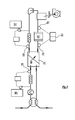
- wastewater enters the apparatus at inlet port 23 at a temperature of twenty degC and a pH of seven.
- the wastewater is contaminated with ammonium at a concentration of 1000 ppm.
- the wastewater travels through the membrane-chamber 25, and around the wastewater circuit 27, and is discharged through the outlet port 29.
- the wastewater enters the wastewater-subchamber 30 of a membrane-chamber 25. Prior to entering the membrane-chamber 25, the wastewater is heated to a temperature of about fifty degC by heater 34. The wastewater circulates around the wastewater-subchamber, and then exits from the wastewater outlet port.
- the pH of the wastewater is also raised, prior to the wastewater entering the membrane-chamber 25.
- Sodium hydroxide (or other suitable base material) is stored in alkali-reservoir 36.
- the NaOH is dosed into the wastewater, under the control of pH-sensor 38 and controller 40.
- the wastewater is raised to a pH of about eleven, prior to entering the membrane-chamber.
- the apparatus as described in Fig.1 would be used on streams that are heavily contaminated (e.g between 500 and 3000 ppm).
- the discharged wastewater is still contaminated, containing e.g fifty or a hundred ppm of ammonia-N, but probably other systems would be more economical at driving that rather low ammonia concentration down to zero.
- -zero- includes: too small to be measured, and too small to matter.
- the apparatus of Fig.1 treats the wastewater, and the secondary-water, on a continuous basis; a batch-treatment system is usually preferred for driving low concentrations to zero.
- the membrane 43 in the membrane-chamber 25 is hydrophobic and gas-permeable. That is to say: a gas such as ammonia, NH3, will pass through the membrane, but water will not.
- the membrane 43 is a hydrophobic material such as polyethylene, or it can be e.g polytetrafluoroethane (PFTE) or other fluoropolymer.
- the predominant form of the ammonia-N in the wastewater-subchamber 30 is ammonia, NH3.
- the rest of the ammonia-N (less than one percent at a pH of eleven) is present as ionised (dissolved) ammonium, NH4+.
- NH4+ ionised ammonium
- the ratio of NH4+ to NH3 remains more or less constant, even though the concentration changes, the ratio being dependent on the pH and redox voltage (and temperature) of the water.
- the more predominantly the ammonia-N in the wastewater is in the form of NH3 the more efficiently and readily the ammonia will pass through the membrane 25 -- hence the expenditure of resources to raise the pH to eleven and the temperature to fifty degC.
- Ammonia emerging through the membrane 43 enters the secondary-water circulating around the secondary circuit 45.
- the secondary-water is at a low pH (e.g a pH of two) as it passes through the secondary-subchamber 47 of the membrane-chamber 25.
- a low pH e.g a pH of two
- the ammonia NH3 that has passed through the membrane 43 now transforms (almost) completely and immediately to ammonium NH4+.
- the ammonium-laden secondary-water then passes into an electrochemical reactor, which includes an electrolytic cell 49.
- the reactor also includes a power unit 50, which supplies suitable current and voltage to the cell.
- the oxidised secondary-water, now with nitrogen gas, is conveyed to a holding tank 52, where the nitrogen gas (along with other products of ammonia oxidation, such as hydrogen gas) is allowed to escape and vent to the atmosphere, aided by an exhaust blower 53.
- the secondary-water, having given up its ammonium, continues around the secondary-circuit 45.
- the secondary-water should be kept at a low pH, and hydrochloric acid, HCl, is stored, for make-up purposes, in acid-reservoir 54.
- the secondary-water is basically hydrochloric acid.
- a pH-sensor 56 and controller 58 (and in-line mixer 60) maintain the acidity of the secondary-water at e.g pH two; however, the secondary-water, in passing through the cell 49, undergoes a drop in pH, and often there is only a minimal requirement for more acid to be added.
- the secondary-water -- with its acidity restored -- can be used over again, and simply circulates and recirculates around the secondary-circuit 45. Another acid can be used, rather than HCl.
- the secondary-water is not heated per se, but gains heat as it passes through the membrane-chamber 25, from the hot wastewater.
- the preferred temperature at which the wastewater should enter the membrane-chamber is about fifty degC. Below that temperature, the ammonia does not pass so easily through the membrane, and about thirty degC should be regarded as the lower limit. As to an upper limit, no further benefit accrues from taking the wastewater much above fifty degC, and sixty degC should be regarded as the limit beyond which the extra heating brings no return.
- the upper limit though, is a commercial one, of balancing the extra expenditure on heat against the savings in membrane efficiency.
- the electrochemical reactor is designed with a series of alternating anode and cathode electrodes, and is operated so as to oxidise the ammonia to nitrogen gas.
- the main electrochemical reactions that occur at the anode are: 2NH4+ --> N2 + 8H+ + 6e 2C1 --> C12 + 2e
- the resulting chemical reactions include: C12 + H2O --> HOCl + HCl 2NH4+ + 3HOCL --> N2 + 3H2O + 5H+ + 3C1
- the overall result is the oxidation of the ammonia to N2 gas.
- the power unit typically supplies DC power at a constant current, with a typical current density range of one hundred to one thousand amps/sq.metre.
- the secondary-circuit was a two-loop circuit.
- the secondary-circuit was divided basically into two parallel flow-streams.
- the secondary-water collected ammonia from the ammonia-extraction station, and in the other flow-stream the secondary-water was conveyed through the electrolysis station.
- the two flow-streams were mixed together by passing through a common tank.
- the secondary circuit is a simple one-loop circuit. That is to say, all the secondary-water passing from the membrane chamber is conveyed to the electrolytic cell, and then all the water is returned to the membrane chamber, in a continuous loop.
- the secondary-water emerging from the membrane-chamber 25 does now have (or can have) some residual pressure, which is (or can be) enough to drive the secondary-water through the electrolysis-station -- hence, in Fig.1 , only one pump is needed for the function of circulating the whole body of secondary-water, being the pump 61 in Fig.1 .
- the present technology briefly: the combination of electrolysis treatment with the extraction of ammonia from the wastewater stream by the use of the membrane -- can, if desired, be used with the kind of two-loop secondary-circuit as was disclosed in US-7,160,430 .
- Fig.2 illustrates one manner in which the two-loop secondary-circuit can be implemented. (In Fig.2 , the wastewater circuit is not illustrated.)
- the secondary-water acquires ammonia from the membrane-chamber 25, in a first loop 63 of the secondary circuit.
- the first loop 63 then conveys the ammonium-laden water into and through an intermediate tank 65.
- pump 67 creates the flow in the first loop.
- a second pump 69 creates the flow of secondary-water around the second loop 79 of the secondary-circuit, conveying the water through the electrolysis cell 49 and through the intermediate tank 65.
- a motorised mixer 72 ensures an absence of differences or gradients of concentration (and of pH, temperature, etc) in the tank 65.
- the ammonia concentration in the secondary-water entering the tank 65 from the first loop 63 is quite different from the concentration in the secondary-water entering the tank from the second loop 70; and yet the secondary-water entering the membrane chamber 25 is the same as the secondary-water entering the cell 49.
- This constant mixing and separating of the secondary-water, via the tank 65, can be effective to increase the efficiency of the disposal of the ammonia-N.
- One advantage of the two-loop circuit as shown in Fig.2 is that the two pumps 67,69 can be set to operate at different flowrates. This can be useful in that the designer might find it difficult to equate the flowrate requirements of the secondary-water as it passes through the ammonium-extraction-station and as it passes through the electrolysis-station -- which must needs be equal in the Fig.1 single-loop secondary-circuit arrangement.
- Fig.3 shows the apparatus of Fig.1 , but now also illustrates pH-sensors 76,78, and controller 80. These elements of Fig.3 are used to enable an efficient, but inexpensive, manner of automated process-control of the operation of the electrochemical-reactor, which will now be described.
- the new manner of process-control involves measuring the pH of the water, instead of measuring the concentration of ammonia in the water, as the basis for process-control. It will be understood that measuring the actual ammonia content of the secondary-water (or of any water) cannot (practically /commercially) be done directly, in real time, nor can it be done cheaply. On the other hand, inexpensive instruments for measuring pH are simple, reliable, and rapidly responsive. The system as described enables the removal of ammonia to be controlled reliably, and at low cost, simply by measuring the pH of the secondary-water.
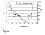
- Fig.3a includes a line-with-circles.
- This line is a graph of ammonia-N concentration in the secondary-water over a period of time.
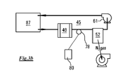
- the line-with-circles was not constructed from measurements taken from the continuous-process system as shown in Fig.3 ; rather, the line-with-circles was constructed using an in-laboratory batch-process treatment system, using the apparatus illustrated in Fig.3b .
- the body of secondary-water occupies a simple vessel 87, which contains no source of further ammonia.
- the secondary-water contains ammonia-N at a concentration of 990 mg/litre.
- the secondary-water is brine, i.e contains NaCl.
- the secondary-water is recirculated through the secondary-circuit, by the pump 52, the secondary-water passing through the cell 49 of the electrochemical reactor.
- the concentration of ammonium in the secondary-water gradually decreases.
- the line-with-circles in Fig.3a represents the decreasing concentration, and shows that the ammonium-N content dropped to zero after about forty-six minutes.
- Fig.3a also includes a line-with-diamonds.
- This line represents the pH of the recirculating secondary-water, measured at intervals, as the concentration of ammonia was falling.
- the pH fell i.e the secondary-water became more acidic
- This fall in pH was due to the electrochemical reactions -- no further acid was added in the in-lab apparatus of Fig.3b .
- the fall in pH started to level off. The pH reached a minimum (actually at a pH of 2.1) just before the ammonia was all gone.
- point C once the ammonia is completely removed, excess chlorine as NaOC1 is formed, and this drives the pH back to (almost) neutral.
- minimum pH of the kind as described with reference to Figs.3a , 3b would be repeated for different ammonia loadings, and different water chemistries. In some cases, the minimum pH can be determined by modelling.
- adjusting the flowrate in the secondary-circuit 45 is usually not an option, since the flowrate is dictated by the requirements of receiving the ammonia from the wastewater.
- the operators will prefer, rather, to adjust the electrical current supplied to the cell 49, as the way of lowering the concentration of ammonium remaining in the secondary-water -- and thereby of changing the pH of the secondary-water.
- the pH as measured at the pH-sensor 78 showed a reading of 2.1, the operators would increase the amperage supplied to the cell. That being done, the residence-time that the secondary-water spends in the cell would be utilised a little more intensely, thereby oxidising the ammonium a little more thoroughly, and the pH would rise again to 2.2.
- the operators start by choosing (i.e guessing) an operating current for the cell, based on the expected ammonia load. Then, the pH-sensor 78 is monitored, and adjustments made to the current so as to drive the pH to 2.2, or other desired target value.
- the same target level of the pH as measured at pH-sensor 78 might apply to a wide range of ammonia loadings.
- the supplied current needed to achieve that target pH would decrease, of course, if the ammonia loading decreased, but the target itself might not change.
- a change in ammonia loading might signal the need for a change in the target pH.
- Experiments would determine whether, and to what extent, changes in target pH should follow changes in ammonia loading.
- ammonia loading can be monitored, not by direct measurement of ammonia content, but by using simple pH sensors.
- the pH-sensors 56 and 76 can be used to determine the magnitude of the lowering of the pH of the secondary-water as the secondary-water passes through the membrane-chamber 25, and picks up its ammonium load. It is recognised that the ammonium concentration in the secondary-water is more or less proportional to the difference in pH between sensor 56 and sensor 76. If a change in this pH drop is detected, the control system can be programmed to move to a new setpoint pH, i.e to a new target pH level for the reading from pH-sensor 78, based on the derived new ammonia-loading. (The reason for a change in the ammonia-load in the body of secondary-water would normally be a change in the ammonia concentration in the incoming contaminated wastewater.)
- the prudent operators will probably carry out e.g periodic checks to determine whether the target pH, with which the control system is directly concerned, is actually achieving the desired degree of elimination of ammonia -- and is achieving that desired degree of elimination by the most economical usage of electrical power and other resources. So, although, as mentioned, it is not desirable to base on-going process-control on on-going direct measurements of ammonia-concentration, nevertheless it is desirable that such measurements should be taken from time to time, as an overall check on the correctness of the indirect parameters used by the control system.
- the apparatus of Fig.4 is, in some respects, similar to that shown in Fig.1 of US-7,160,430 .
- the Fig.4 apparatus is being used for regenerating the column 90, which has become saturated with adsorbed ammonia extracted from the wastewater stream.
- the column is being regenerated to exchange the ammonia ions by sodium ions.
- the column is taken out of service, from the wastewater stream, while the regeneration operation is conducted.
- the regeneration system uses a two-loop secondary-circuit as was described with reference to Fig.2 , and like numerals are used.
- the secondary-water is brine.
- Fig.4a is a graph showing a line-with-circles, which is a plot of the decreasing concentration of ammonia, over a period of time, as the dissolved ammonium is electrolysed and oxidised. ( Fig.4a may be compared with Fig.3a , in this respect.) Both pumps 67,69 are kept running throughout the oxidation treatment described in Fig.4a , circulating and recirculating the secondary-water through the two loops of the secondary circuit, i.e through the column 90 and through the cell 49.
- the pH-control-system operates in two phases.
- a constant current is applied to the cell.
- the operators set the time period of the first phase in that they aim to end the first phase as the concentration of ammonium drops down below e.g ten mg/litre.
- the second phase then commences.
- the aim is to ensure that all the ammonia is gone from the column, and to ensure that that result was accomplished with a minimum expenditure of resources.
- the designer can arrange for the first phase to end and the second phase to start by a simple timer.
- the first phase might last for a period of e.g thirty minutes.
- the pH of the secondary-water in the tank 65 is monitored. If and when the pH, as measured at sensor 56 in Fig.4 , drops below the target level, in this case below a pH of 6.8, the controller 58 signals the reservoir 54 to add a dose of NaOH into the secondary-water in the tank 65. The added alkalinity brings the pH back up above 6.8. Each time the pH falls below 6.8, the controller 58 triggers a new dose of NaOH to be added into the tank 65.
- Fig.4a The wavy line in Fig.4a indicates the fluctuations of pH, following the periodic dosings of NaOH.
- the controller 58 is so programmed that, if/when the pH of the secondary-water goes below 6.8, the controller 58 deposits a dose of NaOH into the tank 65.
- the pH of the secondary-water falls due to the oxidation of the ammonium in the secondary-water, in the cell. (The reaction of the ammonium with the HOCl in the secondary-water also depresses the pH.)
- the deposition of a dose of NaOH into the secondary-water causes the pH to rise.
- the pH of the secondary-water starts to rise again, i.e to rise back up above 6.8.
- the on-going oxidation is causing the pH to fall again; when the pH falls below 6.8, that triggers another dose of NaOH to be added to the tank 49.
- the pH moves up/down, above and below the target-pH, cyclically.
- the amount of the NaOH in the dose is set, by the operators, to procure a manageable cycle time period. For example, a cycle period around five minutes typically is advantageous, to give a good balance between cycle period and magnitude of the variations in pH, in a case where the total time to dispose of (nearly) all the ammonium is e.g forty or fifty minutes, as in the example shown in Fig.4a .
- the size of the dose should be set so that the pH up/down cycle time period is between about two minutes and ten minutes, for example, in practical terms.
- the cycle period can be adjusted by adjusting the amount of NaOH added, per dose, to the tank 65.
- Phase two of the treatment strategy is aimed at reducing the amount of electrical energy fed to the cell during the after-period, being the period in which the last traces of ammonia are being slowly captured from the column.
- the controller 54 includes a timer, and in phase two, the timer is used to determine whether the pH of the secondary-water remains above 6.8 continuously for longer than, for example, about two minutes. If it does, that fact serves to trigger the act of switching the power off to the cell 49.
- the operators can leave the secondary-water circulating around the two loops of the secondary circuit (the pumps 67,69 draw comparatively little electricity) during the after-period, but they can switch off the (large amounts of) power to the cell during the after-period.
- the operators can be confident that, if any more traces of ammonia should be drawn out of the column, the system will detect that fact, and will re-start the pH cycling sequence until it is gone.
Landscapes
- Chemical & Material Sciences (AREA)
- Engineering & Computer Science (AREA)
- Water Supply & Treatment (AREA)
- Organic Chemistry (AREA)
- Hydrology & Water Resources (AREA)
- Environmental & Geological Engineering (AREA)
- Life Sciences & Earth Sciences (AREA)
- Chemical Kinetics & Catalysis (AREA)
- Clinical Laboratory Science (AREA)
- Health & Medical Sciences (AREA)
- Electrochemistry (AREA)
- General Chemical & Material Sciences (AREA)
- Water Treatment By Electricity Or Magnetism (AREA)
- Treatment Of Water By Oxidation Or Reduction (AREA)
- Separation Using Semi-Permeable Membranes (AREA)
- Removal Of Specific Substances (AREA)
- Physical Water Treatments (AREA)
Applications Claiming Priority (1)
| Application Number | Priority Date | Filing Date | Title |
|---|---|---|---|
| GBGB0709109.3A GB0709109D0 (en) | 2007-05-11 | 2007-05-11 | Wastewater ammonium extraction and electrolytic conversion to nitrogen gas |
Publications (2)
| Publication Number | Publication Date |
|---|---|
| EP1990320A2 true EP1990320A2 (fr) | 2008-11-12 |
| EP1990320A3 EP1990320A3 (fr) | 2009-03-11 |
Family
ID=38219260
Family Applications (1)
| Application Number | Title | Priority Date | Filing Date |
|---|---|---|---|
| EP08103930A Withdrawn EP1990320A3 (fr) | 2007-05-11 | 2008-05-12 | Extraction d'ammonium des eaux usées et conversion électrolytique en gaz azote |
Country Status (4)
| Country | Link |
|---|---|
| US (2) | US20080277289A1 (fr) |
| EP (1) | EP1990320A3 (fr) |
| CA (1) | CA2631080A1 (fr) |
| GB (3) | GB0709109D0 (fr) |
Families Citing this family (8)
| Publication number | Priority date | Publication date | Assignee | Title |
|---|---|---|---|---|
| US9527010B2 (en) | 2009-09-25 | 2016-12-27 | Ge Healthcare Bio-Sciences Corp. | Separation system and method |
| US9560839B2 (en) | 2010-11-17 | 2017-02-07 | Technion Research And Development Foundation Ltd. | Physico-chemical process for removal of nitrogen species from recirculated aquaculture systems |
| CN102107977B (zh) * | 2011-01-18 | 2013-05-08 | 南京大学 | 一种含高浓度氨氮废水的资源化方法 |
| US9005333B1 (en) * | 2011-06-20 | 2015-04-14 | The United States Of America, As Represented By The Secretary Of Agriculture | Systems and methods for reducing ammonia emissions from and for recovering the ammonia liquid effluents |
| JP5928070B2 (ja) * | 2012-03-28 | 2016-06-01 | 住友金属鉱山株式会社 | アンモニア含有排水からのアンモニア除去方法 |
| CA3016844C (fr) | 2016-03-08 | 2023-09-26 | Technion Research & Development Foundation Limited | Desinfection et elimination d'especes azotees de systemes d'aquaculture saline |
| CN111196655A (zh) * | 2020-03-13 | 2020-05-26 | 东莞市亿霖环保科技有限公司 | 一种去除氨氮的工业废水处理方法 |
| IL318443B1 (en) * | 2025-01-16 | 2026-03-01 | Purammon Ltd | Electrochemical systems for wastewater treatment and methods of using them |
Citations (1)
| Publication number | Priority date | Publication date | Assignee | Title |
|---|---|---|---|---|
| US7160430B2 (en) | 2002-09-16 | 2007-01-09 | Enpar Technologies Inc. | Electrochemical treatment of ammonia in waste-water |
Family Cites Families (11)
| Publication number | Priority date | Publication date | Assignee | Title |
|---|---|---|---|---|
| US3929600A (en) * | 1974-04-09 | 1975-12-30 | Iwao Engineering Co Inc | Process of removing ammoniacal nitrogen from waste water |
| US4997569A (en) * | 1984-08-28 | 1991-03-05 | The Trustees Of The Stevens Institute Of Technology | Immobilized-interface solute-transfer process |
| JP3235800B2 (ja) * | 1992-12-17 | 2001-12-04 | 東北電力株式会社 | 液中のアンモニウムイオンの除去方法 |
| JPH06182111A (ja) * | 1992-12-17 | 1994-07-05 | Tohoku Electric Power Co Inc | アンモニアガスの脱気方法 |
| JP3235801B2 (ja) * | 1992-12-17 | 2001-12-04 | 東北電力株式会社 | アンモニウムイオンの除去方法 |
| JPH08126886A (ja) * | 1994-10-28 | 1996-05-21 | Japan Organo Co Ltd | 超純水の製造方法及び装置 |
| DE19853182A1 (de) * | 1998-11-19 | 2000-05-25 | Univ Dresden Tech | Verfahren zur elektrochemisch vermittelten Umsetzung von Ammonium aus salzhaltigen Lösungen |
| JP2000317451A (ja) * | 1999-05-10 | 2000-11-21 | Matsushita Electric Ind Co Ltd | アルカリイオン整水器 |
| JP2003001069A (ja) * | 2001-06-18 | 2003-01-07 | Mitsubishi Heavy Ind Ltd | ガス透過膜型前処理装置 |
| US6872296B2 (en) * | 2002-07-30 | 2005-03-29 | INVISTA North America S.à.r.l. | Method for removing ammonia from a gas comprising hydrogen cyanide, ammonia and water |
| WO2008026214A1 (fr) * | 2006-08-31 | 2008-03-06 | Technion Research & Development Foundation Ltd. | Liaison et dissociation commandables d'entités chimiques et dispositif d' électrodes à cet effet |
-
2007
- 2007-05-11 GB GBGB0709109.3A patent/GB0709109D0/en not_active Ceased
-
2008
- 2008-05-12 CA CA002631080A patent/CA2631080A1/fr not_active Abandoned
- 2008-05-12 US US12/118,932 patent/US20080277289A1/en not_active Abandoned
- 2008-05-12 GB GB1203151.4A patent/GB2485710B/en not_active Expired - Fee Related
- 2008-05-12 GB GB0808542.5A patent/GB2449180B/en not_active Expired - Fee Related
- 2008-05-12 EP EP08103930A patent/EP1990320A3/fr not_active Withdrawn
-
2012
- 2012-04-12 US US13/445,081 patent/US20120247973A1/en not_active Abandoned
Patent Citations (1)
| Publication number | Priority date | Publication date | Assignee | Title |
|---|---|---|---|---|
| US7160430B2 (en) | 2002-09-16 | 2007-01-09 | Enpar Technologies Inc. | Electrochemical treatment of ammonia in waste-water |
Also Published As
| Publication number | Publication date |
|---|---|
| GB2485710B (en) | 2012-07-25 |
| GB2449180B (en) | 2012-06-13 |
| CA2631080A1 (fr) | 2008-11-11 |
| GB201203151D0 (en) | 2012-04-11 |
| GB0709109D0 (en) | 2007-06-20 |
| GB2449180A (en) | 2008-11-12 |
| GB0808542D0 (en) | 2008-06-18 |
| EP1990320A3 (fr) | 2009-03-11 |
| US20080277289A1 (en) | 2008-11-13 |
| GB2485710A (en) | 2012-05-23 |
| US20120247973A1 (en) | 2012-10-04 |
Similar Documents
| Publication | Publication Date | Title |
|---|---|---|
| US20120247973A1 (en) | Wastewater ammonium extraction and electrolytic conversion to nitrogen gas | |
| Hashim et al. | Iron removal, energy consumption and operating cost of electrocoagulation of drinking water using a new flow column reactor | |
| Cui et al. | Electrolysis-electrodialysis process for removing chloride ion in wet flue gas desulfurization wastewater (DW): influencing factors and energy consumption analysis | |
| CA2945366C (fr) | Systemes d'administration de traitement et procede pour traiter un plan d'eau | |
| US7160430B2 (en) | Electrochemical treatment of ammonia in waste-water | |
| KR100909209B1 (ko) | 물 처리장치 | |
| WO2014150792A1 (fr) | Système et procédé de traitement électrochimique de l'eau | |
| Lu et al. | Recovery of nickel ions from simulated electroplating rinse water by electrodeionization process | |
| KR20190004789A (ko) | 주기적 회분식 모드로 농축 재순환을 이용하는 전기 화학 시스템 | |
| KR102155238B1 (ko) | 하수 재이용 공정에서 멤브레인 컨텍터를 이용한 암모니아 제거 시스템 및 제어 방법 | |
| WO2015066321A1 (fr) | Appareils et procédés pour conditionnement d'eau, et systèmes et processus les incorporant | |
| WO2009133550A1 (fr) | Procédé électrolytique et chimique intégré pour la production d'eau traitée propre dans laquelle la concentration en l'espèce cyanure est inférieure à 1 milligramme par litre | |
| JP4408706B2 (ja) | 窒素除去方法および装置 | |
| KR101545245B1 (ko) | 알지비 컬러센서와 오알피 센서를 이용한 에칭액 재생 및 구리 회수 장치 | |
| CN110078179A (zh) | 一种火力发电厂废水中氨氮和cod的协同脱除方法及设备 | |
| CN210367089U (zh) | 一种高浓度含氨废水循环电解处理设备 | |
| US20250353770A1 (en) | Systems and methods for wastewater recycling and recovery | |
| CN113388866B (zh) | 线路板含钯废液组合回收系统及方法 | |
| CN115776971A (zh) | 电解水生成装置以及电解水生成装置的控制方法 | |
| HK1239651A1 (en) | Delivery system and method for the treatment of a body of water held in a reservoir | |
| KR20130099386A (ko) | 알칼리성 용액의 오염물질 제거장치 및 방법 |
Legal Events
| Date | Code | Title | Description |
|---|---|---|---|
| PUAI | Public reference made under article 153(3) epc to a published international application that has entered the european phase |
Free format text: ORIGINAL CODE: 0009012 |
|
| AK | Designated contracting states |
Kind code of ref document: A2 Designated state(s): AT BE BG CH CY CZ DE DK EE ES FI FR GB GR HR HU IE IS IT LI LT LU LV MC MT NL NO PL PT RO SE SI SK TR |
|
| AX | Request for extension of the european patent |
Extension state: AL BA MK RS |
|
| RIC1 | Information provided on ipc code assigned before grant |
Ipc: C02F 1/467 20060101ALN20081113BHEP Ipc: C02F 1/461 20060101ALN20081113BHEP Ipc: C02F 1/44 20060101ALN20081113BHEP Ipc: C02F 9/00 20060101AFI20080818BHEP |
|
| PUAL | Search report despatched |
Free format text: ORIGINAL CODE: 0009013 |
|
| AK | Designated contracting states |
Kind code of ref document: A3 Designated state(s): AT BE BG CH CY CZ DE DK EE ES FI FR GB GR HR HU IE IS IT LI LT LU LV MC MT NL NO PL PT RO SE SI SK TR |
|
| AX | Request for extension of the european patent |
Extension state: AL BA MK RS |
|
| 17P | Request for examination filed |
Effective date: 20090911 |
|
| 17Q | First examination report despatched |
Effective date: 20090930 |
|
| AKX | Designation fees paid |
Designated state(s): AT BE BG CH CY CZ DE DK EE ES FI FR GB GR HR HU IE IS IT LI LT LU LV MC MT NL NO PL PT RO SE SI SK TR |
|
| RAP1 | Party data changed (applicant data changed or rights of an application transferred) |
Owner name: ENPAR TECHNOLOGIES INC. |
|
| STAA | Information on the status of an ep patent application or granted ep patent |
Free format text: STATUS: THE APPLICATION IS DEEMED TO BE WITHDRAWN |
|
| 18D | Application deemed to be withdrawn |
Effective date: 20131203 |