EP1990534B1 - Einteiliger aluminium-/hartbeschichteter eloxierter Rotor für Anlasser - Google Patents
Einteiliger aluminium-/hartbeschichteter eloxierter Rotor für Anlasser Download PDFInfo
- Publication number
- EP1990534B1 EP1990534B1 EP08153037.0A EP08153037A EP1990534B1 EP 1990534 B1 EP1990534 B1 EP 1990534B1 EP 08153037 A EP08153037 A EP 08153037A EP 1990534 B1 EP1990534 B1 EP 1990534B1
- Authority
- EP
- European Patent Office
- Prior art keywords
- rotor
- engine
- integral
- starter
- motive fluid
- Prior art date
- Legal status (The legal status is an assumption and is not a legal conclusion. Google has not performed a legal analysis and makes no representation as to the accuracy of the status listed.)
- Active
Links
Images
Classifications
-
- F—MECHANICAL ENGINEERING; LIGHTING; HEATING; WEAPONS; BLASTING
- F02—COMBUSTION ENGINES; HOT-GAS OR COMBUSTION-PRODUCT ENGINE PLANTS
- F02N—STARTING OF COMBUSTION ENGINES; STARTING AIDS FOR SUCH ENGINES, NOT OTHERWISE PROVIDED FOR
- F02N7/00—Starting apparatus having fluid-driven auxiliary engines or apparatus
- F02N7/08—Starting apparatus having fluid-driven auxiliary engines or apparatus the engines being of rotary type
-
- F—MECHANICAL ENGINEERING; LIGHTING; HEATING; WEAPONS; BLASTING
- F02—COMBUSTION ENGINES; HOT-GAS OR COMBUSTION-PRODUCT ENGINE PLANTS
- F02N—STARTING OF COMBUSTION ENGINES; STARTING AIDS FOR SUCH ENGINES, NOT OTHERWISE PROVIDED FOR
- F02N15/00—Other power-operated starting apparatus; Component parts, details, or accessories, not provided for in, or of interest apart from groups F02N5/00 - F02N13/00
-
- Y—GENERAL TAGGING OF NEW TECHNOLOGICAL DEVELOPMENTS; GENERAL TAGGING OF CROSS-SECTIONAL TECHNOLOGIES SPANNING OVER SEVERAL SECTIONS OF THE IPC; TECHNICAL SUBJECTS COVERED BY FORMER USPC CROSS-REFERENCE ART COLLECTIONS [XRACs] AND DIGESTS
- Y10—TECHNICAL SUBJECTS COVERED BY FORMER USPC
- Y10T—TECHNICAL SUBJECTS COVERED BY FORMER US CLASSIFICATION
- Y10T29/00—Metal working
- Y10T29/49—Method of mechanical manufacture
- Y10T29/49229—Prime mover or fluid pump making
- Y10T29/49236—Fluid pump or compressor making
- Y10T29/49238—Repairing, converting, servicing or salvaging
Definitions
- the present invention relates to rotors for air engine starters for internal combustion engines.
- Starter systems as for example disclosed in US6533541 B1 or US6318958 B1 often include an air motor driven by pressurized air and a gear system. Pressurized air is introduced to the air motor, causing a rotor to rotate.
- the rotor which has a higher number of revolutions per minute (rpm) than what is needed to start the engine, is connected to the gear system, which includes one or more speed reducing gears configured to match the air motor rpm to the engine rpm.
- the reducing gears drive an output device such as a pinion, which is coupled to the engine. Rotation of the pinion in turn rotates the engine, initiating operation of the engine.
- the invention provides a starter for moving a movable portion of an engine to start the engine.
- the starter includes a gear housing having first and second opposite ends, a gear assembly within the gear housing and including a plurality of speed-reducing gears, an output member at the first end of the gear assembly aligned with the movable portion of the engine and adapted to operably couple to the movable portion of the engine, a motor housing having a first end mounted to the second end of the gear housing and a second end opposite the first end, a motive fluid inlet adapted to permit a flow of motive fluid into the motor housing, a rotor rotatably mounted within the motor housing and a motive fluid outlet mounted to the second end of the motor housing, and adapted to exhaust the motive fluid to a desired destination after the motive fluid has flown through the motor housing.
- the rotor has a shaft portion and a vane portion that are an integral, unitary piece.
- the shaft portion has splines for mating with the gear assembly. The splines prevent relative rotational movement between the rotor and the gear assembly and permit relative axial movement.
- the rotor is formed from aluminum and at least a portion of the rotor includes an anodized coating.
- the rotor can further include a stub portion on an opposite side of the vane portion as the shaft portion, the stub portion being integrally formed with the vane portion and the shaft portion.
- substantially the entire surface of the rotor includes an anodized coating.
- the anodized coating can be a hard anodized coating, and can have a thickness of from about 0.0005 - 0.0045 inches.
- the rotor can be a solid member.
- the invention provides a method of servicing a starter for moving a movable portion of an engine to start the engine.
- the method includes accessing a service aperture in the starter, removing a rotor from the starter through the service aperture, removing an air motor shaft from the starter through the service aperture and replacing the rotor and the air motor shaft with an integral rotor.
- the integral rotor has a shaft portion and a vane portion that are an integral, unitary piece.
- the shaft portion has splines for coupling to a movable portion of the engine in which the splines prevent relative rotational movement between the integral rotor and the movable portion and permit relative axial movement.
- the integral rotor is formed from aluminum and at least a portion of the integral rotor includes an anodized coating.
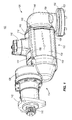
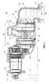
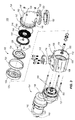
- Figs. 1 - 3 illustrate a starter system 100 according to one embodiment of the invention.
- Starter system 100 can couple to an engine 101 ( Fig. 2 ) for providing start-up cranking of the engine 101.
- Starter system 100 can be used with any type of engine, including but not limited to, internal combustion engines, diesel engines, and turbine and microturbine engines.
- Starter system 100 can include an air motor module 102, a gear assembly 104 and motive fluid outlet 106.
- the gear assembly 104 is at the front of the starter system 100 oriented towards the engine 101 while the motive fluid outlet 106 is at the rear of the starter system 100 away from the engine 101.
- the air motor module 102 can include an air motor housing 108 with a motive fluid inlet 110 for receiving a motive fluid, such as pressurized air or natural gas, into the air motor housing 108, and a service aperture 112 at one end of the housing 108.
- the air motor housing 108 can define an air motor chamber 114 in fluid communication with the motive fluid inlet 110 via a channel 116.
- the air motor module 102 can further include a rotor 122, a stator 124, a stator housing 128 and a containment ring 130 arranged along the longitudinal axis 125.
- the stator 124 can be secured to the stator housing128 against rotation by way of fasteners 129.
- the stator 124 can direct the flow of motive fluid against the rotor 122 to cause rotation of the rotor 122 with respect to the stator 124.
- the motive fluid may be provided in the range of 30 - 150 psig
- the stator 124 may act as a supersonic nozzle
- the rotor 122 may be designed to have a free turbine or "run away" speed of 65,000 rpm.
- the rotor 122 can be interconnected with the gear assembly 104 via, for example, an air motor shaft 134.
- the air motor shaft 134 is supported for rotation by bearings in the motor housing 108.
- the gear assembly 104 can include one or more speed reducing gears 136 and a planetary gear 137 within a gear housing 138.
- Mounted at opposite ends of the reducing gears 136 and the planetary gear 137 are the air motor shaft 134 and an output member 140.
- the reducing gears 136 and the planetary gear 137 cause rotation of the output member 140 in response to rotation of the air motor shaft 134, while reducing speed and increasing torque of the output member 140 compared to the air motor shaft 134.
- the reducing gears 136 and/or the planetary gear 137 may be excluded from the starter system 100. As shown in Fig.
- the gear housing 136 is offset from the longitudinal axis 125 so that the output member 140 is offset from the longitudinal axis 125. In other embodiments, however, the gear housing 136 and/or the output member 140 is arranged along the longitudinal axis 125 as well.
- the output member 140 can be, for example, a pinion.
- the output member 140 can interface (e.g., through direct meshing with a gear, or through a belt, a chain, a plurality of gears, or any other suitable means for transferring rotation and torque) with a movable portion, mechanism, or member 141 of the engine 101 and can be operable to move the movable portion 141 of the engine 101 in response to rotation of the reducing gears 136 in the gear housing 138.
- the movable portion 141 of the engine 101 may include, for example, a crankshaft, a gear or other torque transfer member, and other movable parts.
- the rotor 122 rotates at a first speed in response to the flow of motive fluid through the channel 116 and chamber 114 of the motor housing 108.
- the planetary gear 137 rotates in response to rotation of the rotor 122 via the air motor shaft 134 and drives the speed-reducing gears 136.
- the output member 140 rotates at a second speed slower than the first speed in response to rotation of the speed-reducing gears 136 to cause the movable portion 141 of the engine 101 to move and start the engine 101.
- the output member 140 can be said to transfer torque from the starter system 100 to the engine 101. This movement of the movable portion 141 of the engine 101 by the output member 140 can effectively start the engine 101.
- the gear housing 138 can include a flange 142 at an end opposite the air motor shaft 134. The flange 142 facilitates mounting the gear assembly 104 to the engine 101 or near the engine 101 to engage the output member 140 with the movable portion 141 of the engine 101.
- the motive fluid outlet 106 can provide an exhaust system for the motive fluid from the starter system 100.
- the motive fluid outlet 106 can direct the flow of motive fluid out of the air motor housing 108 after the motive fluid has flown past the rotor 122.
- the motive fluid outlet 106 can include an exhaust cap 143 mounted to the air motor housing 108 over the service aperture 112.
- the output member 140 and mounting flange 142 are at a first end of the gear housing 138, a second end of the gear housing 138 (opposite the first end) is mounted to a first end of the motor housing 108, a second end of the motor housing 108 (opposite the first end) defines the service aperture 112 and has mounted thereon the exhaust cap 143.
- a debris screen 144 can be positioned between the air motor housing 108 and the exhaust cap 143 for trapping debris.
- An O-ring seal 146 can also be positioned between the air motor housing 108 and the exhaust cap 143 to prevent motive fluid leakage.
- the exhaust cap 143, debris screen 144 and O-ring seal 146 can be arranged along the longitudinal axis 125 as well.
- the motive fluid outlet 106 can further include a conduit 148 for directing exhaust motive fluid away from the starter system 100.
- the conduit 148 can be, for example, an elbow.
- the conduit 148 can include a pipe flange 150 for mounting the conduit 148 to a pipe coupling 152 to facilitate securing the conduit 148 to a pipe or other structure for directing the exhaust motive fluid to a remote location.
- the elbow version of the conduit 148 illustrated in the drawings may be employed in applications that use natural gas or another combustible gaseous fuel as the motive fluid, as for example, at a site that has a ready supply of such fuel for the engine 101 or another device.
- the pipe to which the conduit 148 is secured through the pipe coupling 152 may direct the natural gas or other combustible gaseous fuel to a flare or the combustion chamber of another device for immediate combustion, or may recapture the natural gas or other combustible gaseous fuel for future use.
- the conduit 148 may be replaced with a diffuser mounted to the exhaust cap 143.
- the diffuser would lower the pressure of the motive fluid prior to venting the motive fluid to the atmosphere or ambient surroundings. Such diffuser may be particularly useful in applications using compressed air as the motive fluid.
- the term "desired destination" is used herein to refer to the atmosphere, conduits, flares, combustion chambers, or any other destination for the motive fluid upon flowing out of the motive fluid outlet 106.
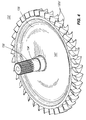
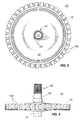
- Figs. 4-6 illustrate a rotor 122' according to an embodiment of the invention.
- the rotor 122' includes an air motor shaft portion 134', a vane portion 135' and a stub portion 137'.
- the rotor 122' can replace the rotor 122 and air motor shaft 134 of the embodiment shown generally in Figs. 1-3 .
- the air motor shaft portion 134' can be supported for rotation on bearings on a forward side of the rotor 122', while the stub portion 137' can be supported for rotation on bearings on a rear side of the rotor 122' (bearings not shown).
- the flow of motive fuel over the vane portion 135' drives rotation of the rotor 122', including rotation of the air motor shaft portion 134'.
- the rotor 122' is a unitary member, in that the air motor shaft portion 134', the vane portion 135' and the stub portion 137' are integrally formed with one another as a single, unitary piece. Because the air motor shaft portion 134', the vane portion 135' and the stub portion 137' are integral with one another, connectors, fasteners or other mechanical or non-mechanical connectors for connecting the vane portion 135' to the air motor shaft portion 134' and to the stub portion 137' are not required.
- the rotor 122' is formed of a lightweight material such as aluminum. All or a portion of an outer surface 141' of the rotor 122' is anodized to provide the rotor 122' with an outer anodic coating.
- the process of forming an anodic coating on aluminum is well known in the art of materials processing, and may be accomplished according to various methods so as to produce anodic coatings having varying strength, wear and finish characteristics. In general, however, the anodic coating provides the rotor 122' with improved strength and wear characteristics in relation to non-anodized aluminum.
- all or a portion of the outer surface 141' of the rotor 122' can be hard anodized.
- the rotor 122' can have a hard anodic coating that is at least approximately 25 microns thick. In one embodiment, at least a portion of the rotor 122' includes an anodic coating substantially equivalent to a type III, Mil-A-8625F, hard anodic coating.
- a type III, Mil-A-8625F hard anodic coating has a nominal thickness of from about 0.0005 - 0.0045 inches and does not vary by more than +/- 20% for coatings up to 0.002 inches thick.
- a type III, Mil-A-8625F hard anodic coating has a minimum coating weight of 4320 milligrams per square foot for 0.001 inch of coating.
- a type III, Mil-A-8625F hard anodic coating has a maximum wear index of 3.5 mg/1000 cycles on aluminum alloys having a copper content of 2% or higher.
- a type III, Mil-A-8625F hard anodic coating has a maximum wear index 1.5 mg/1000 cycles for all other alloys.
- the rotor 122' is a solid member. By solid, it is meant that the rotor 122' lacks apertures, openings, internal hollows, cavities, voids or other discontinuities. This does not include individual spaced apart vanes 135'a formed about a periphery of the vane portion 135' acted on by the motive fluid to rotate the rotor 122'. Openings for receiving fasteners for connecting the air motor shaft 134 to the rotor 122 are eliminated because the rotor 122' is a unitary, single piece with the vane portion 135 integrally formed with the air motor shaft portion 134'.
- the lack of apertures and other voids in the rotor 122' (i.e., that the rotor 122' is a solid member) provides a more uniform distribution of rotational stresses throughout the rotor 122', especially at takeoff. Because rotational stresses are distributed more uniformly, the rotor 122' need not be formed of a heavy duty material, such as steel, as would be necessary to withstand localized rotational stresses caused by apertures, discontinuities or voids.
- the air motor shaft portion 134' includes a plurality of splines or axially oriented ribs and grooves 139'.
- the splines 139' of the air motor shaft portion 134' can mate with a component (not shown) of the gear assembly 104 having complementary splining in a male to female relationship.
- the rotor 122' can be interconnected with the gear assembly 104 via the air motor shaft portion 134'.
- the mated splines 139' permit the rotor 122' to impart torque output or rotational energy to the gear assembly 104 via the air motor shaft portion 134'.
- the splining arrangement permits relative axial movement between the air motor shaft portion 134' and the gear assembly 104.
- the air motor shaft portion 134' can slide in a rearward and forward direction relative to the gear assembly 104.
- This axial play is useful in aligning the air motor shaft portion 134' with the input side of the gear assembly 104, and relieves the need for precise axial positioning of the input side of the gear assembly 104 with the air motor shaft portion 134'.
- the flow of motive fluid over the rotor 122' induces an axial thrust force on the rotor 122'.
- Wave springs or other biasing members may be provided between the air motor shaft portion 134' and the motor housing 102 for absorbing the axial thrust force.
- the splining arrangement permits some axial play of the rotor 122' as such biasing members collapse. This reduces localized stresses and wear on the rotor 122' due to the axial thrust force not borne by the gear assembly 104.
- the rotor 122' is illustrated and described as a component of the engine starter 100.
- the rotor 122' can, however, be sized and shaped for use with other types of engine starters, and for other types of air motors in general.
- the engine starter 100 can be serviced by accessing the service aperture 112 and removing the rotor 122 and the air motor shaft 134 from the starter 100 through the service aperture 112.
- the rotor 122 and the air motor shaft 134 can be replaced with the rotor 122'.
- the invention provides a method for retro-fitting an existing air starter with a single piece rotor/output shaft part.
- the invention provides, among other things, an air motor engine starter having a unitary rotor construction.
Landscapes
- Engineering & Computer Science (AREA)
- Chemical & Material Sciences (AREA)
- Combustion & Propulsion (AREA)
- Mechanical Engineering (AREA)
- General Engineering & Computer Science (AREA)
- Connection Of Motors, Electrical Generators, Mechanical Devices, And The Like (AREA)
- Hydraulic Motors (AREA)
Claims (14)
- Rotor für einen Motoranlasser zum Bewegen eines beweglichen Abschnitts eines Motors, um den Motor zu starten, wobei der Rotor Folgendes aufweist:einen Rotor mit einem Wellenabschnitt und einem Leitschaufelabschnitt, wobei der Wellenabschnitt und der Leitschaufelabschnitt miteinander integral sind, um so ein integrales, einziges Teil zu sein, wobei der Wellenabschnitt Keile zur Kopplung an einen beweglichen Abschnitt des Motors aufweist, wobei die Keile eine relative Drehbewegung zwischen dem Rotor und dem beweglichen Abschnitt verhindern und eine relative axiale Bewegung zulassen, wobei der Rotor aus Aluminium ausgeführt ist und mindestens ein Abschnitt des Rotors eine eloxierte Beschichtung aufweist.
- Rotor nach Anspruch 1, wobei der Rotor weiter einen Stutzenabschnitt an einer dem Wellenabschnitt gegenüber liegenden Seite des Leitschaufelabschnitts aufweist, wobei der Stutzenabschnitt integral mit dem Leitschaufelabschnitt und dem Wellenabschnitt ausgebildet ist.
- Rotor nach Anspruch 1, wobei im Wesentlichen die gesamte Oberfläche des Rotors eine eloxierte Schicht aufweist.
- Rotor nach Anspruch 1, wobei die eloxierte Schicht eine harteloxierte Schicht ist.
- Rotor nach Anspruch 1, wobei die eloxierte Schicht eine Dicke von etwa 0,0005 - 0,0045 Zoll besitzt.
- Rotor nach Anspruch 1, wobei der Rotor ein massives Bauteil ist.
- Anlasser zum Bewegen eines beweglichen Abschnitts eines Motors, um den Motor zu starten, wobei der Anlasser Folgendes aufweist:ein Getriebegehäuse mit einem ersten und zweiten gegenüberliegenden Ende;eine Getriebebaugruppe innerhalb des Getriebegehäuses, welche eine Vielzahl von Untersetzungszahnrädern aufweist;ein Ausgangsbauelement an dem ersten Ende der Getriebebaugruppe, welches dafür angepasst ist, wirksam an den beweglichen Abschnitt des Motors anzukoppeln; ein Motorgehäuse mit einem ersten Ende, welches an dem zweiten Ende des Getriebegehäuses montiert ist, und einem dem ersten Ende gegenüber liegenden zweiten Ende;einen Einlass für Antriebsfluid, welcher dafür angepasst ist, einen Strom von Antriebsfluid in das Motorgehäuse zu ermöglichen;einen Rotor gemäß einem der Ansprüche 1 bis 6, welcher innerhalb des Motorgehäuses montiert und innerhalb des Gehäuses unter der Einwirkung des Stroms von Antriebsfluid drehbar ist; undeinen Auslass für Antriebsfluid, welcher an dem zweiten Ende des Motorgehäuses montiert ist und dafür angepasst ist, um das Antriebsfluid zu einem gewünschten Zielort auszustoßen, nachdem das Antriebsfluid durch das Motorgehäuse geströmt ist.
- Verfahren zur Instandhaltung eines Starters zum Bewegen eines beweglichen Abschnitts eines Motors, um den Motor zu starten, wobei das Verfahren Folgendes aufweist:Zugang zu einer Wartungsöffnung in dem Anlasser erlangen;Entfernen eines Rotors von dem Anlasser durch die Wartungsöffnung;Entfernen einer Luftmotorwelle von dem Anlasser durch die Wartungsöffnung;Ersetzen des Rotors und der Luftmotorwelle durch einen integralen Rotor mit einem Wellenabschnitt und einem Leitschaufelabschnitt, wobei der Wellenabschnitt und der Leitschaufelabschnitt ein integrales, einziges Teil sind, wobei der Wellenabschnitt Keile zur Kopplung an einen beweglichen Abschnitt des Motors aufweist, wobei die Keile eine relative Drehbewegung zwischen dem integralen Rotor und dem beweglichen Abschnitt verhindern und eine relative axiale Bewegung zulassen, wobei der integrale Rotor aus Aluminium ausgeführt ist und mindestens ein Abschnitt des integralen Rotors eine eloxierte Beschichtung aufweist.
- Verfahren nach Anspruch 8, wobei der Rotor weiter einen Stutzenabschnitt an einer dem Wellenabschnitt gegenüber liegenden Seite des Leitschaufelabschnitts aufweist, wobei der Stutzenabschnitt ein integrales, einziges Teil mit dem Leitschaufelabschnitt und dem Wellenabschnitt ist.
- Verfahren nach Anspruch 8, wobei im Wesentlichen die gesamte Oberfläche des integralen Rotors eine eloxierte Schicht aufweist.
- Verfahren nach Anspruch 8, wobei die eloxierte Schicht eine harteloxierte Schicht ist.
- Verfahren nach Anspruch 8, wobei die eloxierte Schicht eine Dicke von etwa 0,0005 - 0,0045 Zoll besitzt.
- Verfahren nach Anspruch 8, wobei der integrale Rotor ein massives Bauteil ist.
- Verfahren nach Anspruch 8, wobei der Rotor und die Luftmotorwelle mit Befestigungsmitteln aneinander montiert werden.
Applications Claiming Priority (1)
| Application Number | Priority Date | Filing Date | Title |
|---|---|---|---|
| US11/746,758 US7665439B2 (en) | 2007-05-10 | 2007-05-10 | Single piece rotor |
Publications (3)
| Publication Number | Publication Date |
|---|---|
| EP1990534A2 EP1990534A2 (de) | 2008-11-12 |
| EP1990534A3 EP1990534A3 (de) | 2012-05-16 |
| EP1990534B1 true EP1990534B1 (de) | 2016-10-19 |
Family
ID=39608857
Family Applications (1)
| Application Number | Title | Priority Date | Filing Date |
|---|---|---|---|
| EP08153037.0A Active EP1990534B1 (de) | 2007-05-10 | 2008-03-19 | Einteiliger aluminium-/hartbeschichteter eloxierter Rotor für Anlasser |
Country Status (2)
| Country | Link |
|---|---|
| US (1) | US7665439B2 (de) |
| EP (1) | EP1990534B1 (de) |
Families Citing this family (4)
| Publication number | Priority date | Publication date | Assignee | Title |
|---|---|---|---|---|
| US20100162983A1 (en) * | 2008-12-30 | 2010-07-01 | Mcgrew Bruce | Pneumatic starting system |
| US9726132B2 (en) * | 2015-06-24 | 2017-08-08 | Phillip Pawlicki | Barring-tool system and method |
| US11459992B1 (en) * | 2021-06-15 | 2022-10-04 | Caterpillar Inc. | Delay circuit for providing natural gas to an engine and systems, assemblies, and methods thereof |
| CN115585055A (zh) * | 2022-11-04 | 2023-01-10 | 重庆金皇后新能源汽车制造有限公司 | 一种加力大环转换器、传动系统及汽车 |
Family Cites Families (52)
| Publication number | Priority date | Publication date | Assignee | Title |
|---|---|---|---|---|
| US1598820A (en) | 1923-04-07 | 1926-09-07 | Gen Motors Corp | Engine-starting apparatus |
| US1760988A (en) | 1925-11-23 | 1930-06-03 | Eclipse Machine Co | Engine starter |
| US2154572A (en) * | 1936-11-19 | 1939-04-18 | Eclipse Aviat Corp | Motor control mechanism |
| US2358445A (en) * | 1943-04-05 | 1944-09-19 | Mid Continent Supply Company | Engine starter and actuating mechanism therefor |
| US2441990A (en) | 1944-09-02 | 1948-05-25 | Evan A Calhoun | Starter mounting |
| GB643069A (en) * | 1948-04-06 | 1950-09-15 | Rolls Royce | Improvements in or relating to starting gear for internal combustion engines |
| US3010443A (en) | 1959-03-19 | 1961-11-28 | Garland E Lyvers | Engine starting device |
| US3313239A (en) * | 1965-06-30 | 1967-04-11 | Dover Corp | Vane-type pump |
| US3791365A (en) | 1972-03-20 | 1974-02-12 | Ingersoll Rand Co | Air starter |
| US3816040A (en) * | 1972-11-09 | 1974-06-11 | Stanadyne Inc | Air starter and lubricator throttle valve therefor |
| FR2331186A1 (fr) | 1975-11-07 | 1977-06-03 | Paris & Du Rhone | Perfectionnements aux demarreurs electriques |
| US4273085A (en) * | 1977-06-22 | 1981-06-16 | Janik Jr Leon P | Air starter |
| US4126113A (en) * | 1977-10-17 | 1978-11-21 | Sarro Manuel B | Engine air starter |
| US4274292A (en) * | 1979-10-11 | 1981-06-23 | Arnett Jr Robert D | Compact starter assembly |
| US4362065A (en) | 1981-10-08 | 1982-12-07 | Samar, Import And Export, Inc. | Replacement starting motor assembly |
| USRE33919E (en) * | 1985-09-26 | 1992-05-12 | Sycon Corporation | Pneumatic starter for internal combustion engine |
| US4839245A (en) * | 1985-09-30 | 1989-06-13 | Union Carbide Corporation | Zirconium nitride coated article and method for making same |
| US4830571A (en) * | 1986-02-24 | 1989-05-16 | Tech Development Inc. | Pneumatic starters |
| US4914906A (en) * | 1988-05-24 | 1990-04-10 | Allied-Signal Inc. | Turbine starter device |
| US4960085A (en) * | 1988-08-31 | 1990-10-02 | Tech Development Inc. | Pneumatic and electro-pneumatic starters |
| KR920006243B1 (ko) | 1989-02-17 | 1992-08-01 | 미쓰비시전기주식회사 | 스타터 장치 |
| JPH0317281U (de) | 1989-06-30 | 1991-02-20 | ||
| SE465527B (sv) | 1990-02-09 | 1991-09-23 | Svenska Rotor Maskiner Ab | Skruvrotormaskin med organ foer axialbalansering |
| IT220454Z2 (it) | 1990-06-20 | 1993-09-22 | Magneti Marelli Spa | Involucro di sopporto per un motore elettrico di avviamento di un motore a combustione interna, particolarmente per autoveicoli |
| JPH04183242A (ja) | 1990-11-16 | 1992-06-30 | Nippondenso Co Ltd | 始動機兼発電機 |
| US5134330A (en) | 1991-02-12 | 1992-07-28 | Milton Haas | Apparatus to replace crimp-mounted solenoids on starter motors |
| US5163335A (en) | 1991-07-15 | 1992-11-17 | Patrick D. Isom | Universal starter motor assembly |
| US5291861A (en) * | 1992-06-02 | 1994-03-08 | Ingersoll-Rand Company | Moving starter system |
| US5394681A (en) * | 1992-08-11 | 1995-03-07 | Charles Nolan | Radius roller |
| US5267539A (en) * | 1992-09-01 | 1993-12-07 | Tech Development, Inc. | Electro-pneumatic engine starter |
| US5329896A (en) | 1993-01-06 | 1994-07-19 | Ryobi Outdoor Products, Inc. | Replaceable recoil starter |
| US5767585A (en) | 1993-12-27 | 1998-06-16 | Nippondenso Co., Ltd. | Starter |
| US5387088A (en) * | 1994-01-18 | 1995-02-07 | Haemonetics Corporation | Peristaltic pump tube loading assembly |
| JP3133893B2 (ja) | 1994-04-28 | 2001-02-13 | 三菱電機株式会社 | スタータ装置 |
| US5836739A (en) | 1995-03-17 | 1998-11-17 | Rolls-Royce Plc | Gas turbine engine |
| US5831340A (en) | 1995-05-25 | 1998-11-03 | Nippondenso Co., Ltd. | Starter with high vibration resistance construction |
| JPH09203365A (ja) | 1996-01-26 | 1997-08-05 | Denso Corp | スタータ |
| JP3669532B2 (ja) | 1996-09-20 | 2005-07-06 | 株式会社デンソー | スタータ |
| DE19955061A1 (de) | 1999-11-15 | 2001-05-23 | Bosch Gmbh Robert | Startanlage für eine Verbrennungskraftmaschine |
| JP3838868B2 (ja) | 2000-12-05 | 2006-10-25 | 株式会社デンソー | エンジン始動装置 |
| US6559566B2 (en) | 2001-02-12 | 2003-05-06 | Emerson Electric Co. | End shield constructed with a separate component holder |
| US6533541B1 (en) * | 2001-12-04 | 2003-03-18 | Honeywell International, Inc. | High energy particle arrestor for air turbine starters |
| US6633099B2 (en) | 2001-12-05 | 2003-10-14 | Delco Remy America, Inc. | Engagement and disengagement mechanism for a coaxial starter motor assembly |
| JP4039208B2 (ja) | 2002-10-24 | 2008-01-30 | 株式会社デンソー | 内燃機関用スタータ |
| KR20040093588A (ko) | 2003-04-30 | 2004-11-06 | 발레오전장시스템스코리아 주식회사 | 차량용 스타터 모터의 하우징 체결구조 |
| JP4111053B2 (ja) | 2003-05-16 | 2008-07-02 | 株式会社デンソー | スタータ |
| US6969235B2 (en) | 2003-05-19 | 2005-11-29 | Honeywell International, Inc. | Air turbine starter with angular contact thrust bearing |
| US6921251B2 (en) * | 2003-09-05 | 2005-07-26 | General Electric Company | Aluminide or chromide coating of turbine engine rotor component |
| DE10347842A1 (de) * | 2003-10-10 | 2005-04-28 | Daimler Chrysler Ag | Verdichter- und Turbinenrad für eine Sekundärluftfördereinrichtung |
| US7217099B2 (en) * | 2005-05-24 | 2007-05-15 | General Electric Company | Coated forward stub shaft dovetail slot |
| JP2008074390A (ja) * | 2006-08-23 | 2008-04-03 | Yamaha Motor Co Ltd | 船舶用プロペラおよび船外機 |
| US7584676B2 (en) * | 2007-04-18 | 2009-09-08 | Ingersoll Rand Company | Rear serviceable engine starter |
-
2007
- 2007-05-10 US US11/746,758 patent/US7665439B2/en active Active
-
2008
- 2008-03-19 EP EP08153037.0A patent/EP1990534B1/de active Active
Also Published As
| Publication number | Publication date |
|---|---|
| EP1990534A3 (de) | 2012-05-16 |
| EP1990534A2 (de) | 2008-11-12 |
| US7665439B2 (en) | 2010-02-23 |
| US20080276893A1 (en) | 2008-11-13 |
Similar Documents
| Publication | Publication Date | Title |
|---|---|---|
| US7040082B2 (en) | Assistance and emergency drive for electrically-driven accessories | |
| CN100554664C (zh) | 双轴涡轮发动机、其动力输出模块和装配该发动机的方法 | |
| US9574500B2 (en) | Direct metering using a variable displacement vane pump | |
| CN107532517A (zh) | 具有悬臂压缩机和涡轮机的复合发动机组件 | |
| WO2012004516A1 (fr) | Procédé et architecture de recombinaison de puissance de turbomachine | |
| CN105392967A (zh) | 改进的涡轮机中间壳体及附件齿轮箱驱动组件 | |
| CN114076036B (zh) | 空气涡轮启动器 | |
| CA3091487A1 (en) | Oil tank for geared turbofan engine | |
| US7665439B2 (en) | Single piece rotor | |
| CN107532506A (zh) | 具有模块化压缩机和涡轮机的发动机组件 | |
| WO2015107308A1 (fr) | Ensemble d'entraînement d'accessoires pour turbomachine d'aeronef | |
| CN113090347B (zh) | 具有轴承冷却的空气起动器 | |
| EP3789594B1 (de) | Verbrennungsmotoren mit unidirektionalen kompoundierungsantrieben | |
| EP1983188B1 (de) | Motoranlasser, der von hinten wartbar ist | |
| US7806011B2 (en) | Balanced bearing assembly | |
| US11933227B2 (en) | Air starter with offset interface | |
| EP2721271B1 (de) | Zweikolben-turbinenmotordesign mit an die niederdruckturbine angeschlossenem hochdruckverdichter | |
| FR2887924A1 (fr) | Dispositif de guidage d'un flux d'air entre un compresseur et une chambre de combustion dans une turbomachine | |
| CN112610659A (zh) | 周转齿轮系统外壳组件 | |
| US11933295B2 (en) | Tapered shafts for fluid pumps | |
| EP4552973A1 (de) | Kompaktes flugzeugtriebwerk mit propeller mit variabler steigung und ölübertragungsring | |
| EP4219899A1 (de) | Turbolader | |
| EP3617518B1 (de) | Pumpe einer turbomaschine | |
| WO2025099132A1 (en) | Compact aircraft engine with variable pitch propeller and oil transfer ring | |
| RU2266419C2 (ru) | Воздушно-реактивный дизельный двигатель |
Legal Events
| Date | Code | Title | Description |
|---|---|---|---|
| PUAI | Public reference made under article 153(3) epc to a published international application that has entered the european phase |
Free format text: ORIGINAL CODE: 0009012 |
|
| AK | Designated contracting states |
Kind code of ref document: A2 Designated state(s): AT BE BG CH CY CZ DE DK EE ES FI FR GB GR HR HU IE IS IT LI LT LU LV MC MT NL NO PL PT RO SE SI SK TR |
|
| AX | Request for extension of the european patent |
Extension state: AL BA MK RS |
|
| PUAL | Search report despatched |
Free format text: ORIGINAL CODE: 0009013 |
|
| AK | Designated contracting states |
Kind code of ref document: A3 Designated state(s): AT BE BG CH CY CZ DE DK EE ES FI FR GB GR HR HU IE IS IT LI LT LU LV MC MT NL NO PL PT RO SE SI SK TR |
|
| AX | Request for extension of the european patent |
Extension state: AL BA MK RS |
|
| RIC1 | Information provided on ipc code assigned before grant |
Ipc: F02N 7/08 20060101AFI20120410BHEP Ipc: F02N 15/00 20060101ALI20120410BHEP |
|
| 17P | Request for examination filed |
Effective date: 20120731 |
|
| AKX | Designation fees paid |
Designated state(s): DE FR GB IT SE |
|
| GRAP | Despatch of communication of intention to grant a patent |
Free format text: ORIGINAL CODE: EPIDOSNIGR1 |
|
| INTG | Intention to grant announced |
Effective date: 20160509 |
|
| GRAS | Grant fee paid |
Free format text: ORIGINAL CODE: EPIDOSNIGR3 |
|
| GRAA | (expected) grant |
Free format text: ORIGINAL CODE: 0009210 |
|
| RAP1 | Party data changed (applicant data changed or rights of an application transferred) |
Owner name: INGERSOLL RAND COMPANY |
|
| RBV | Designated contracting states (corrected) |
Designated state(s): DE FR GB IT |
|
| AK | Designated contracting states |
Kind code of ref document: B1 Designated state(s): DE FR GB IT |
|
| REG | Reference to a national code |
Ref country code: GB Ref legal event code: FG4D |
|
| REG | Reference to a national code |
Ref country code: DE Ref legal event code: R096 Ref document number: 602008046869 Country of ref document: DE |
|
| REG | Reference to a national code |
Ref country code: FR Ref legal event code: PLFP Year of fee payment: 10 |
|
| REG | Reference to a national code |
Ref country code: DE Ref legal event code: R097 Ref document number: 602008046869 Country of ref document: DE |
|
| PLBE | No opposition filed within time limit |
Free format text: ORIGINAL CODE: 0009261 |
|
| STAA | Information on the status of an ep patent application or granted ep patent |
Free format text: STATUS: NO OPPOSITION FILED WITHIN TIME LIMIT |
|
| 26N | No opposition filed |
Effective date: 20170720 |
|
| REG | Reference to a national code |
Ref country code: FR Ref legal event code: PLFP Year of fee payment: 11 |
|
| REG | Reference to a national code |
Ref country code: GB Ref legal event code: 732E Free format text: REGISTERED BETWEEN 20200806 AND 20200812 |
|
| REG | Reference to a national code |
Ref country code: DE Ref legal event code: R081 Ref document number: 602008046869 Country of ref document: DE Owner name: INGERSOLL-RAND INDUSTRIAL U.S., INC. (N.D.GES., US Free format text: FORMER OWNER: INGERSOLL-RAND CO., MONTVALE, N.J., US |
|
| REG | Reference to a national code |
Ref country code: DE Ref legal event code: R082 Ref document number: 602008046869 Country of ref document: DE Representative=s name: MURGITROYD GERMANY PATENTANWALTSGESELLSCHAFT M, DE Ref country code: DE Ref legal event code: R082 Ref document number: 602008046869 Country of ref document: DE Representative=s name: HL KEMPNER PATENTANWALT, RECHTSANWALT, SOLICIT, DE Ref country code: DE Ref legal event code: R082 Ref document number: 602008046869 Country of ref document: DE Representative=s name: MURGITROYD & COMPANY, DE |
|
| REG | Reference to a national code |
Ref country code: DE Ref legal event code: R082 Ref document number: 602008046869 Country of ref document: DE Representative=s name: MURGITROYD GERMANY PATENTANWALTSGESELLSCHAFT M, DE Ref country code: DE Ref legal event code: R082 Ref document number: 602008046869 Country of ref document: DE Representative=s name: MURGITROYD & COMPANY, DE |
|
| PGFP | Annual fee paid to national office [announced via postgrant information from national office to epo] |
Ref country code: GB Payment date: 20220328 Year of fee payment: 15 |
|
| P01 | Opt-out of the competence of the unified patent court (upc) registered |
Effective date: 20230523 |
|
| GBPC | Gb: european patent ceased through non-payment of renewal fee |
Effective date: 20230319 |
|
| PG25 | Lapsed in a contracting state [announced via postgrant information from national office to epo] |
Ref country code: GB Free format text: LAPSE BECAUSE OF NON-PAYMENT OF DUE FEES Effective date: 20230319 |
|
| PG25 | Lapsed in a contracting state [announced via postgrant information from national office to epo] |
Ref country code: GB Free format text: LAPSE BECAUSE OF NON-PAYMENT OF DUE FEES Effective date: 20230319 |
|
| PGFP | Annual fee paid to national office [announced via postgrant information from national office to epo] |
Ref country code: DE Payment date: 20250331 Year of fee payment: 18 |
|
| PGFP | Annual fee paid to national office [announced via postgrant information from national office to epo] |
Ref country code: IT Payment date: 20260320 Year of fee payment: 19 |
|
| PGFP | Annual fee paid to national office [announced via postgrant information from national office to epo] |
Ref country code: FR Payment date: 20260327 Year of fee payment: 19 |