EP1990538A2 - Dispositif de freinage d'un rotor d'une éolienne - Google Patents
Dispositif de freinage d'un rotor d'une éolienne Download PDFInfo
- Publication number
- EP1990538A2 EP1990538A2 EP08015451A EP08015451A EP1990538A2 EP 1990538 A2 EP1990538 A2 EP 1990538A2 EP 08015451 A EP08015451 A EP 08015451A EP 08015451 A EP08015451 A EP 08015451A EP 1990538 A2 EP1990538 A2 EP 1990538A2
- Authority
- EP
- European Patent Office
- Prior art keywords
- rotor
- rotor blades
- power supply
- rotation
- brake
- Prior art date
- Legal status (The legal status is an assumption and is not a legal conclusion. Google has not performed a legal analysis and makes no representation as to the accuracy of the status listed.)
- Withdrawn
Links
- 230000004888 barrier function Effects 0.000 claims description 2
- 230000005484 gravity Effects 0.000 description 4
- 238000012423 maintenance Methods 0.000 description 3
- 238000009434 installation Methods 0.000 description 2
- 230000007547 defect Effects 0.000 description 1
- 238000005265 energy consumption Methods 0.000 description 1
- 230000001105 regulatory effect Effects 0.000 description 1
Images
Classifications
-
- F—MECHANICAL ENGINEERING; LIGHTING; HEATING; WEAPONS; BLASTING
- F03—MACHINES OR ENGINES FOR LIQUIDS; WIND, SPRING, OR WEIGHT MOTORS; PRODUCING MECHANICAL POWER OR A REACTIVE PROPULSIVE THRUST, NOT OTHERWISE PROVIDED FOR
- F03D—WIND MOTORS
- F03D7/00—Controlling wind motors
- F03D7/02—Controlling wind motors the wind motors having rotation axis substantially parallel to the air flow entering the rotor
- F03D7/022—Adjusting aerodynamic properties of the blades
- F03D7/0224—Adjusting blade pitch
-
- F—MECHANICAL ENGINEERING; LIGHTING; HEATING; WEAPONS; BLASTING
- F03—MACHINES OR ENGINES FOR LIQUIDS; WIND, SPRING, OR WEIGHT MOTORS; PRODUCING MECHANICAL POWER OR A REACTIVE PROPULSIVE THRUST, NOT OTHERWISE PROVIDED FOR
- F03D—WIND MOTORS
- F03D7/00—Controlling wind motors
- F03D7/02—Controlling wind motors the wind motors having rotation axis substantially parallel to the air flow entering the rotor
-
- F—MECHANICAL ENGINEERING; LIGHTING; HEATING; WEAPONS; BLASTING
- F03—MACHINES OR ENGINES FOR LIQUIDS; WIND, SPRING, OR WEIGHT MOTORS; PRODUCING MECHANICAL POWER OR A REACTIVE PROPULSIVE THRUST, NOT OTHERWISE PROVIDED FOR
- F03D—WIND MOTORS
- F03D7/00—Controlling wind motors
- F03D7/02—Controlling wind motors the wind motors having rotation axis substantially parallel to the air flow entering the rotor
- F03D7/0244—Controlling wind motors the wind motors having rotation axis substantially parallel to the air flow entering the rotor for braking
- F03D7/0248—Controlling wind motors the wind motors having rotation axis substantially parallel to the air flow entering the rotor for braking by mechanical means acting on the power train
-
- F—MECHANICAL ENGINEERING; LIGHTING; HEATING; WEAPONS; BLASTING
- F05—INDEXING SCHEMES RELATING TO ENGINES OR PUMPS IN VARIOUS SUBCLASSES OF CLASSES F01-F04
- F05B—INDEXING SCHEME RELATING TO WIND, SPRING, WEIGHT, INERTIA OR LIKE MOTORS, TO MACHINES OR ENGINES FOR LIQUIDS COVERED BY SUBCLASSES F03B, F03D AND F03G
- F05B2260/00—Function
- F05B2260/70—Adjusting of angle of incidence or attack of rotating blades
- F05B2260/75—Adjusting of angle of incidence or attack of rotating blades the adjusting mechanism not using auxiliary power sources, e.g. servos
-
- F—MECHANICAL ENGINEERING; LIGHTING; HEATING; WEAPONS; BLASTING
- F05—INDEXING SCHEMES RELATING TO ENGINES OR PUMPS IN VARIOUS SUBCLASSES OF CLASSES F01-F04
- F05B—INDEXING SCHEME RELATING TO WIND, SPRING, WEIGHT, INERTIA OR LIKE MOTORS, TO MACHINES OR ENGINES FOR LIQUIDS COVERED BY SUBCLASSES F03B, F03D AND F03G
- F05B2260/00—Function
- F05B2260/70—Adjusting of angle of incidence or attack of rotating blades
- F05B2260/76—Adjusting of angle of incidence or attack of rotating blades the adjusting mechanism using auxiliary power sources
-
- F—MECHANICAL ENGINEERING; LIGHTING; HEATING; WEAPONS; BLASTING
- F05—INDEXING SCHEMES RELATING TO ENGINES OR PUMPS IN VARIOUS SUBCLASSES OF CLASSES F01-F04
- F05B—INDEXING SCHEME RELATING TO WIND, SPRING, WEIGHT, INERTIA OR LIKE MOTORS, TO MACHINES OR ENGINES FOR LIQUIDS COVERED BY SUBCLASSES F03B, F03D AND F03G
- F05B2260/00—Function
- F05B2260/70—Adjusting of angle of incidence or attack of rotating blades
- F05B2260/78—Adjusting of angle of incidence or attack of rotating blades the adjusting mechanism driven or triggered by aerodynamic forces
-
- F—MECHANICAL ENGINEERING; LIGHTING; HEATING; WEAPONS; BLASTING
- F05—INDEXING SCHEMES RELATING TO ENGINES OR PUMPS IN VARIOUS SUBCLASSES OF CLASSES F01-F04
- F05B—INDEXING SCHEME RELATING TO WIND, SPRING, WEIGHT, INERTIA OR LIKE MOTORS, TO MACHINES OR ENGINES FOR LIQUIDS COVERED BY SUBCLASSES F03B, F03D AND F03G
- F05B2260/00—Function
- F05B2260/70—Adjusting of angle of incidence or attack of rotating blades
- F05B2260/79—Bearing, support or actuation arrangements therefor
-
- F—MECHANICAL ENGINEERING; LIGHTING; HEATING; WEAPONS; BLASTING
- F05—INDEXING SCHEMES RELATING TO ENGINES OR PUMPS IN VARIOUS SUBCLASSES OF CLASSES F01-F04
- F05B—INDEXING SCHEME RELATING TO WIND, SPRING, WEIGHT, INERTIA OR LIKE MOTORS, TO MACHINES OR ENGINES FOR LIQUIDS COVERED BY SUBCLASSES F03B, F03D AND F03G
- F05B2270/00—Control
- F05B2270/10—Purpose of the control system
- F05B2270/107—Purpose of the control system to cope with emergencies
-
- Y—GENERAL TAGGING OF NEW TECHNOLOGICAL DEVELOPMENTS; GENERAL TAGGING OF CROSS-SECTIONAL TECHNOLOGIES SPANNING OVER SEVERAL SECTIONS OF THE IPC; TECHNICAL SUBJECTS COVERED BY FORMER USPC CROSS-REFERENCE ART COLLECTIONS [XRACs] AND DIGESTS
- Y02—TECHNOLOGIES OR APPLICATIONS FOR MITIGATION OR ADAPTATION AGAINST CLIMATE CHANGE
- Y02E—REDUCTION OF GREENHOUSE GAS [GHG] EMISSIONS, RELATED TO ENERGY GENERATION, TRANSMISSION OR DISTRIBUTION
- Y02E10/00—Energy generation through renewable energy sources
- Y02E10/70—Wind energy
- Y02E10/72—Wind turbines with rotation axis in wind direction
Definitions
- the invention relates to a device for adjusting rotatably mounted on a rotor hub of a wind turbine rotor blades, with electrical devices in the rotor hub, such as a drive for rotating the rotor blades, with a connected to the rotor blades lock in case of failure of the power supply of the drive or the drive is itself activated, and which prevents in the activated state, a rotation of the rotor blades in the operating position, with a rotor brake and with an emergency power supply.
- Such a device is known from WO 99/23384 A1 known.
- a lock on the rotor blade adjustment is provided for braking the system, which is activated in case of failure of the power supply, causing the rotor blades can rotate only in the feathered position and held in this until the plant came to a standstill and restored the power supply is.
- this device ensures a safe braking of the system in case of power failure, it is a disadvantage that, for a reliable operation of this device, a relatively large sweep, ie an angle between the longitudinal axis of the rotor blade and its axis of rotation, is required, though in unfavorable cases, the rotor blades without drive, which in turn would need an emergency power supply to be turned into the feathered position.
- a large sweep also causes large loads in normal operation, which requires the use of larger adjustment drives for the rotor blades. As a result, this leads to higher installation costs and higher energy consumption and worsens the dynamics of the drives due to higher mass inertia of the drives.
- EP 1 128 064 A is a device for adjusting rotatably mounted on a rotor hub of a wind turbine rotor blades with drives for rotating the rotor blades and with an emergency power supply known.
- For emergency power supply of the drives at least one arranged on the rotor shaft permanent magnet generator is provided.
- the invention is therefore the object of a device to provide the type mentioned, in which the deceleration of the rotor works reliably even if no sweep or only a small sweep available and no own emergency power supply for each drive each rotor blade are provided.
- the invention uses the always present in wind turbines in itself rotor brake, which is used in accordance with the relevant provisions only as a holding brake in the maintenance of the wind turbine or as an emergency brake failure of a system component, in conjunction with the lock for rotating the rotor blades in the feathered position.
- the invention makes use of the fact that through the use of the rotor brake, a torque acts on the rotor blades, which rotates them in the feathered position. At the same time act on the rotor blades gravity and wind forces, which support a rotation of the rotor blades in the feathered position.
- a very fast and safe rotation of the rotor blades can be effected in the feathering without a large sweep or support required by the rotor blade drives with a necessary redundant emergency power supply in the form of batteries.
- the supply of arranged in the hub electrical devices, such as the drives for rotating the rotor blades can be done exclusively via a rotary electrical connection, such as slip rings on the rotor shaft, with an emergency power supply outside the hub, e.g. in the nacelle or in the tower of the wind turbine, for example, in short grid interruptions, ensures the continuous supply of the adjusting drives and the system can always be turned off regulated. Should, however, e.g.
- the slip ring, any connection line or the drive emergency shutdown may be required, the braking torque of the rotor brake in conjunction with the inertia of the rotor blades for rapid and reliable rotation of the rotor blades in the feathered position and thus ensures safe shutdown of the system.
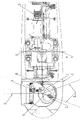
- a nacelle 1 of a wind turbine is schematically shown, on which a hub 2 is rotatably mounted.
- rotor blades 3 are rotatably supported by their axes of rotation.
- a drive consisting of motor 4 and frequency converter 5 per rotor blade 3 is provided in each case.
- Each motor 4 is equipped with a lock that prevents rotation of the rotor blades 3 in the operating position in the activated state, but allows a continuous or discontinuous rotation of the rotor blades 3 in the feathered position.
- the lock In the non-activated state, the lock is inactive, ie a rotation of the rotor blades 3 in all directions is possible.
- the lock can z. B. as in the WO 99/23384 A1 be described and work.
- the barrier can also be designed so that it only catches the rotor blades 3 in the feathered position and prevents them from turning back to the operating position.
- Each frequency converter 5 is connected via a line 6 to a motor 4.
- the power supply of the frequency converter 5 via a connecting line 7 which is connected to a slip ring 8 on the rotor shaft.
- a slip ring 8 is gondola side via a further connecting line 9, an emergency power supply 10, z. B. with a battery or an accumulator connected.
- a rotor brake 11 is provided, which serves for braking and for holding the rotor or the rotor hub 2.
- the control of the system and the lock on the engine 4 are designed so that when an interruption of the power supply, for. B. by a failure of the motor 4, the slip ring 8 or a breakage of the lines 6, 7, 9 or a defect in the frequency converter 5, which makes an emergency shutdown of the system with the fastest possible braking of the rotor required, the rotor brake 11 and the lock be activated on the drive 4. As a result, the rotor is braked by the rotor brake 11 and at the same time the lock prevents rotation of the rotor blades 3 in the operating position.
- Mass inertia of the rotor blades 3 and the position of the center of gravity outside its axis of rotation are rotated by the braking torque of the rotor brake 11 in the feathered position, with wind forces and gravity support this rotation of the rotor blades 3 in the feathered position at least temporarily or at intervals. It is not required by the braking torque of the rotor brake 11 additional measures, such as an emergency power supply of the drives 4, 5 or provide a large sweep of the rotor blades 3, as provided by the rotor brake 11 sufficiently high torques for rapid rotation of the rotor blades 3 in the feathered position be put.
- the drives 4 for controlled shutdown of the system as needed, for example, in case of failure of the electrical connection between the system and the network, in which it feeds power to provide emergency power, if a functioning power / control connection between system control, frequency converter 5 and motor 4 consists.
- the rotor brake 11 may be designed as a more powerful brake, this can be dimensioned in the invention only as an emergency and maintenance brake, because the rotor brake 11 must be used only in an emergency, that is, in case of failure of one of the components and the rotor blades 3 in conjunction with the lock not go through the sweep or a lying outside the axis of rotation of the rotor blades 3 center of gravity of the rotor blades 3 alone in the feathered position and when the rotor reaches a supercritical speed.
Landscapes
- Engineering & Computer Science (AREA)
- Life Sciences & Earth Sciences (AREA)
- Sustainable Development (AREA)
- Sustainable Energy (AREA)
- Chemical & Material Sciences (AREA)
- Combustion & Propulsion (AREA)
- Mechanical Engineering (AREA)
- General Engineering & Computer Science (AREA)
- Physics & Mathematics (AREA)
- Fluid Mechanics (AREA)
- Wind Motors (AREA)
Applications Claiming Priority (2)
| Application Number | Priority Date | Filing Date | Title |
|---|---|---|---|
| AT0046805A AT500843B8 (de) | 2005-03-18 | 2005-03-18 | Verfahren und vorrichtung zum abbremsen des rotors einer windkraftanlage |
| EP06704743A EP1866543B1 (fr) | 2005-03-18 | 2006-03-09 | Procédé et dispositif permettant de faire freiner le rotor d'une éolienne |
Related Parent Applications (1)
| Application Number | Title | Priority Date | Filing Date |
|---|---|---|---|
| EP06704743A Division EP1866543B1 (fr) | 2005-03-18 | 2006-03-09 | Procédé et dispositif permettant de faire freiner le rotor d'une éolienne |
Publications (2)
| Publication Number | Publication Date |
|---|---|
| EP1990538A2 true EP1990538A2 (fr) | 2008-11-12 |
| EP1990538A3 EP1990538A3 (fr) | 2009-11-11 |
Family
ID=36096722
Family Applications (2)
| Application Number | Title | Priority Date | Filing Date |
|---|---|---|---|
| EP06704743A Expired - Lifetime EP1866543B1 (fr) | 2005-03-18 | 2006-03-09 | Procédé et dispositif permettant de faire freiner le rotor d'une éolienne |
| EP08015451A Withdrawn EP1990538A3 (fr) | 2005-03-18 | 2006-03-09 | Dispositif de freinage d'un rotor d'une éolienne |
Family Applications Before (1)
| Application Number | Title | Priority Date | Filing Date |
|---|---|---|---|
| EP06704743A Expired - Lifetime EP1866543B1 (fr) | 2005-03-18 | 2006-03-09 | Procédé et dispositif permettant de faire freiner le rotor d'une éolienne |
Country Status (13)
| Country | Link |
|---|---|
| US (1) | US20110058943A9 (fr) |
| EP (2) | EP1866543B1 (fr) |
| JP (1) | JP4953469B2 (fr) |
| KR (1) | KR100961732B1 (fr) |
| CN (1) | CN101142404A (fr) |
| AT (1) | AT500843B8 (fr) |
| AU (1) | AU2006225057B2 (fr) |
| BR (1) | BRPI0608534A2 (fr) |
| CA (1) | CA2601675C (fr) |
| DK (1) | DK1866543T3 (fr) |
| ES (1) | ES2386310T3 (fr) |
| MX (1) | MX2007011442A (fr) |
| WO (1) | WO2006096895A1 (fr) |
Cited By (1)
| Publication number | Priority date | Publication date | Assignee | Title |
|---|---|---|---|---|
| DE102017102375B3 (de) | 2017-02-07 | 2018-06-28 | Hoerbiger Automatisierungstechnik Holding Gmbh | Windkraftanlage |
Families Citing this family (3)
| Publication number | Priority date | Publication date | Assignee | Title |
|---|---|---|---|---|
| AT507394B1 (de) * | 2008-10-09 | 2012-06-15 | Gerald Dipl Ing Hehenberger | Windkraftanlage |
| US8018082B2 (en) * | 2009-11-25 | 2011-09-13 | General Electric Company | Method and apparatus for controlling a wind turbine |
| CN112253386B (zh) * | 2020-10-15 | 2024-07-12 | 华能酒泉风电有限责任公司 | 风力发电设备及其叶片自变桨控制方法、系统和装置 |
Citations (2)
| Publication number | Priority date | Publication date | Assignee | Title |
|---|---|---|---|---|
| WO1999023384A1 (fr) | 1997-11-04 | 1999-05-14 | Gerald Hehenberger | Entrainement pour pales de rotor d'installations eoliennes |
| EP1128064A2 (fr) | 2000-02-28 | 2001-08-29 | Norbert Hennchen | Dispositif électrique pour changer l'angle d'attaque des aubes d'une éolienne |
Family Cites Families (21)
| Publication number | Priority date | Publication date | Assignee | Title |
|---|---|---|---|---|
| US4297075A (en) * | 1979-05-14 | 1981-10-27 | Jacobs Marcellus L | Automatic storm protection control for wind energy system |
| US4490093A (en) * | 1981-07-13 | 1984-12-25 | U.S. Windpower, Inc. | Windpower system |
| NL8204845A (nl) * | 1982-03-26 | 1983-10-17 | Fdo Techn Adviseurs | Bladverstelmechanisme voor de rotorbladen van een windmolen. |
| US4692093A (en) * | 1982-05-28 | 1987-09-08 | The Garrett Corporation | Ram air turbine |
| US4474531A (en) * | 1982-12-27 | 1984-10-02 | U.S. Windpower, Inc. | Windmill with direction-controlled feathering |
| JPS6045787A (ja) * | 1983-08-22 | 1985-03-12 | Matsushita Seiko Co Ltd | 風力原動機の非常停止装置 |
| DE9015887U1 (de) * | 1990-11-22 | 1991-04-18 | Mroz, Franz, 4408 Dülmen | Windkraftmaschine |
| DE29722109U1 (de) * | 1997-12-16 | 1998-03-26 | aerodyn Engineering GmbH, 24768 Rendsburg | Windenergieanlage |
| US6327957B1 (en) * | 1998-01-09 | 2001-12-11 | Wind Eagle Joint Venture | Wind-driven electric generator apparatus of the downwind type with flexible changeable-pitch blades |
| DE19811952A1 (de) * | 1998-03-15 | 1999-09-16 | Tacke Windenergie Gmbh | Verfahren zur Verstellung der Rotorblätter einer Windkraftanlage |
| WO2000009885A1 (fr) * | 1998-08-13 | 2000-02-24 | Neg Micon A/S | Procede et dispositif de reglage du pas et d'arret de la rotation des pales d'une eolienne |
| US6265785B1 (en) * | 1998-11-30 | 2001-07-24 | Zond Systems, Inc. | Non-volatile over speed control system for wind turbines |
| DE19948997B4 (de) * | 1999-10-11 | 2005-04-14 | Aerodyn Engineering Gmbh | Einzelblattverstellung für Windenergieanlagen |
| NZ513769A (en) * | 2001-08-24 | 2001-09-28 | William Currie | A wind turbine |
| DE10145414B4 (de) * | 2001-09-14 | 2013-09-12 | Aloys Wobben | Verfahren zur Errichtung einer Windenergieanlage, Windenergieanlage |
| CN1284928C (zh) * | 2001-12-28 | 2006-11-15 | 三菱重工业株式会社 | 逆风型风力涡轮机及其操作方法 |
| ES2266833T3 (es) * | 2002-04-26 | 2007-03-01 | General Electric Company | Dispositivo para ajustar las palas del rotor de una turbina de energia eolica. |
| DE10338127C5 (de) * | 2003-08-15 | 2015-08-06 | Senvion Se | Windenergieanlage mit einem Rotor |
| WO2007098759A2 (fr) * | 2006-02-28 | 2007-09-07 | Vestas Wind Systems A/S | Rotor d'éolienne, mécanisme de commande de rotation et procédé de commande d'au moins une pale d'un rotor d'éolienne |
| DE102006015511A1 (de) * | 2006-03-31 | 2007-10-04 | Robert Bosch Gmbh | Windkraftanlage |
| US7218012B1 (en) * | 2006-05-31 | 2007-05-15 | General Electric Company | Emergency pitch drive power supply |
-
2005
- 2005-03-18 AT AT0046805A patent/AT500843B8/de not_active IP Right Cessation
-
2006
- 2006-03-09 WO PCT/AT2006/000101 patent/WO2006096895A1/fr not_active Ceased
- 2006-03-09 KR KR1020077023734A patent/KR100961732B1/ko not_active Expired - Lifetime
- 2006-03-09 ES ES06704743T patent/ES2386310T3/es not_active Expired - Lifetime
- 2006-03-09 EP EP06704743A patent/EP1866543B1/fr not_active Expired - Lifetime
- 2006-03-09 CA CA2601675A patent/CA2601675C/fr not_active Expired - Fee Related
- 2006-03-09 AU AU2006225057A patent/AU2006225057B2/en not_active Ceased
- 2006-03-09 MX MX2007011442A patent/MX2007011442A/es active IP Right Grant
- 2006-03-09 DK DK06704743.1T patent/DK1866543T3/da active
- 2006-03-09 CN CNA2006800088247A patent/CN101142404A/zh active Pending
- 2006-03-09 BR BRPI0608534-2A patent/BRPI0608534A2/pt not_active IP Right Cessation
- 2006-03-09 US US11/908,570 patent/US20110058943A9/en not_active Abandoned
- 2006-03-09 JP JP2008501103A patent/JP4953469B2/ja not_active Expired - Fee Related
- 2006-03-09 EP EP08015451A patent/EP1990538A3/fr not_active Withdrawn
Patent Citations (2)
| Publication number | Priority date | Publication date | Assignee | Title |
|---|---|---|---|---|
| WO1999023384A1 (fr) | 1997-11-04 | 1999-05-14 | Gerald Hehenberger | Entrainement pour pales de rotor d'installations eoliennes |
| EP1128064A2 (fr) | 2000-02-28 | 2001-08-29 | Norbert Hennchen | Dispositif électrique pour changer l'angle d'attaque des aubes d'une éolienne |
Cited By (2)
| Publication number | Priority date | Publication date | Assignee | Title |
|---|---|---|---|---|
| DE102017102375B3 (de) | 2017-02-07 | 2018-06-28 | Hoerbiger Automatisierungstechnik Holding Gmbh | Windkraftanlage |
| WO2018145948A1 (fr) | 2017-02-07 | 2018-08-16 | Hoerbiger Automatisierungstechnik Holding Gmbh | Aérogénérateur |
Also Published As
| Publication number | Publication date |
|---|---|
| CA2601675A1 (fr) | 2006-09-21 |
| US20090304506A1 (en) | 2009-12-10 |
| KR20070116111A (ko) | 2007-12-06 |
| JP2008533364A (ja) | 2008-08-21 |
| CN101142404A (zh) | 2008-03-12 |
| US20110058943A9 (en) | 2011-03-10 |
| BRPI0608534A2 (pt) | 2010-01-12 |
| AU2006225057A2 (en) | 2008-02-28 |
| AT500843B8 (de) | 2007-02-15 |
| WO2006096895A1 (fr) | 2006-09-21 |
| ES2386310T3 (es) | 2012-08-16 |
| KR100961732B1 (ko) | 2010-06-10 |
| EP1866543A1 (fr) | 2007-12-19 |
| AU2006225057A1 (en) | 2006-09-21 |
| MX2007011442A (es) | 2008-03-10 |
| AT500843A4 (de) | 2006-04-15 |
| AT500843B1 (de) | 2006-04-15 |
| EP1866543B1 (fr) | 2012-05-16 |
| AU2006225057B2 (en) | 2011-12-01 |
| EP1990538A3 (fr) | 2009-11-11 |
| JP4953469B2 (ja) | 2012-06-13 |
| DK1866543T3 (da) | 2012-07-23 |
| CA2601675C (fr) | 2010-09-21 |
Similar Documents
| Publication | Publication Date | Title |
|---|---|---|
| EP1747365B1 (fr) | Installation eolienne pourvue d'un generateur auxiliaire, et son procede de commande | |
| DE60311896T2 (de) | Redundantes steuerungssystem zur verstellung der anstellwinkel der rotorblätter einer windkraftanlage | |
| EP1654459B1 (fr) | Installation eolienne munie d'un dispositif de reglage des pales de rotor | |
| EP1029176B1 (fr) | Installation eolienne | |
| US7958797B2 (en) | Turning device | |
| EP2116722B1 (fr) | Positionnement du rotor d'une éolienne | |
| EP3892852B1 (fr) | Éolienne verticale, ainsi que procédé de fonctionnement d'une telle éolienne | |
| DE102010031081A1 (de) | Windenergieanlage | |
| EP1887221B1 (fr) | Eolienne et dispositif de réglage du pas de l'hélice pour éolienne | |
| EP1337755B1 (fr) | Eolienne | |
| DE102007052863B4 (de) | Verfahren zum Betreiben einer Windenergieanlage | |
| DE102013004580A1 (de) | Verfahren zum Arretieren einer Windturbine und Windturbine zur Durchführung des Verfahrens | |
| DE19644705A1 (de) | Vorrichtung zur Verstellung von Rotorblättern | |
| DE102011079269A1 (de) | Sicherheitskette und Verfahren zum Betreiben einer Windturbine | |
| EP3649343B1 (fr) | Unité de commande mobile pour une éolienne | |
| WO2012025348A2 (fr) | Système de pas pour éolienne | |
| EP1866543B1 (fr) | Procédé et dispositif permettant de faire freiner le rotor d'une éolienne | |
| DE10116011B4 (de) | Windenergieanlage | |
| EP3940226B1 (fr) | Éolienne et procédé de fonctionnement d'une éolienne | |
| DE202004009071U1 (de) | Windenergieanlage mit einem Hilfsgenerator | |
| EP3242013A1 (fr) | Éolienne comprenant un dispositif destine a faire tourner une nacelle de l'eolienne et procede de montage d'un dispositif destine a faire tourner une nacelle | |
| DE102004007461A1 (de) | Verfahren zum Betreiben einer Windkraftanlage, und dementsprechend ausgestaltete Windkraftanlage |
Legal Events
| Date | Code | Title | Description |
|---|---|---|---|
| PUAI | Public reference made under article 153(3) epc to a published international application that has entered the european phase |
Free format text: ORIGINAL CODE: 0009012 |
|
| 17P | Request for examination filed |
Effective date: 20080902 |
|
| AC | Divisional application: reference to earlier application |
Ref document number: 1866543 Country of ref document: EP Kind code of ref document: P |
|
| AK | Designated contracting states |
Kind code of ref document: A2 Designated state(s): AT BE BG CH CY CZ DE DK EE ES FI FR GB GR HU IE IS IT LI LT LU LV MC NL PL PT RO SE SI SK TR |
|
| AX | Request for extension of the european patent |
Extension state: AL BA HR MK YU |
|
| RAP1 | Party data changed (applicant data changed or rights of an application transferred) |
Owner name: AMSC WINDTEC GMBH |
|
| PUAL | Search report despatched |
Free format text: ORIGINAL CODE: 0009013 |
|
| AK | Designated contracting states |
Kind code of ref document: A3 Designated state(s): AT BE BG CH CY CZ DE DK EE ES FI FR GB GR HU IE IS IT LI LT LU LV MC NL PL PT RO SE SI SK TR |
|
| AX | Request for extension of the european patent |
Extension state: AL BA HR MK YU |
|
| AKX | Designation fees paid |
Designated state(s): AT BE BG CH CY CZ DE DK EE ES FI FR GB GR HU IE IS IT LI LT LU LV MC NL PL PT RO SE SI SK TR |
|
| AXX | Extension fees paid |
Extension state: YU Payment date: 20080902 Extension state: MK Payment date: 20080902 Extension state: HR Payment date: 20080902 Extension state: BA Payment date: 20080902 Extension state: AL Payment date: 20080902 |
|
| STAA | Information on the status of an ep patent application or granted ep patent |
Free format text: STATUS: THE APPLICATION HAS BEEN WITHDRAWN |
|
| 18W | Application withdrawn |
Effective date: 20131001 |