EP1990608A2 - Auf Rotationsrate um zwei Achsen sensitiver MEMS-Stimmgabelkreisel - Google Patents
Auf Rotationsrate um zwei Achsen sensitiver MEMS-Stimmgabelkreisel Download PDFInfo
- Publication number
- EP1990608A2 EP1990608A2 EP08156021A EP08156021A EP1990608A2 EP 1990608 A2 EP1990608 A2 EP 1990608A2 EP 08156021 A EP08156021 A EP 08156021A EP 08156021 A EP08156021 A EP 08156021A EP 1990608 A2 EP1990608 A2 EP 1990608A2
- Authority
- EP
- European Patent Office
- Prior art keywords
- rotation
- sense electrodes
- proof masses
- drive
- processing device
- Prior art date
- Legal status (The legal status is an assumption and is not a legal conclusion. Google has not performed a legal analysis and makes no representation as to the accuracy of the status listed.)
- Granted
Links
Images


Classifications
-
- B—PERFORMING OPERATIONS; TRANSPORTING
- B81—MICROSTRUCTURAL TECHNOLOGY
- B81B—MICROSTRUCTURAL DEVICES OR SYSTEMS, e.g. MICROMECHANICAL DEVICES
- B81B7/00—Microstructural systems ; Auxiliary parts of microstructural devices or systems
-
- G—PHYSICS
- G01—MEASURING; TESTING
- G01C—MEASURING DISTANCES, LEVELS OR BEARINGS; SURVEYING; NAVIGATION; GYROSCOPIC INSTRUMENTS; PHOTOGRAMMETRY OR VIDEOGRAMMETRY
- G01C19/00—Gyroscopes; Turn-sensitive devices using vibrating masses; Turn-sensitive devices without moving masses; Measuring angular rate using gyroscopic effects
- G01C19/56—Turn-sensitive devices using vibrating masses, e.g. vibratory angular rate sensors based on Coriolis forces
- G01C19/5719—Turn-sensitive devices using vibrating masses, e.g. vibratory angular rate sensors based on Coriolis forces using planar vibrating masses driven in a translation vibration along an axis
- G01C19/5726—Signal processing
-
- B—PERFORMING OPERATIONS; TRANSPORTING
- B81—MICROSTRUCTURAL TECHNOLOGY
- B81B—MICROSTRUCTURAL DEVICES OR SYSTEMS, e.g. MICROMECHANICAL DEVICES
- B81B7/00—Microstructural systems ; Auxiliary parts of microstructural devices or systems
- B81B7/02—Microstructural systems ; Auxiliary parts of microstructural devices or systems containing distinct electrical or optical devices of particular relevance for their function, e.g. microelectro-mechanical systems [MEMS]
-
- G—PHYSICS
- G01—MEASURING; TESTING
- G01C—MEASURING DISTANCES, LEVELS OR BEARINGS; SURVEYING; NAVIGATION; GYROSCOPIC INSTRUMENTS; PHOTOGRAMMETRY OR VIDEOGRAMMETRY
- G01C19/00—Gyroscopes; Turn-sensitive devices using vibrating masses; Turn-sensitive devices without moving masses; Measuring angular rate using gyroscopic effects
Definitions
- the present invention provides a two-axes MEMS gyroscope system.
- the system includes two proof masses, two drive components, two drive sense components, two Coriolis sense electrodes sensitive to out-of-plane proof mass motion, two Coriolis sense electrodes sensitive to in-plane proof mass motion, and a processing device.
- the processing device is in signal communication with the two proof masses, the drive electrodes, the drive sense components, the in plane Coriolis sense electrodes and the out of plane Coriolis sense electrodes.
- the processing device determines the rate of rotation about two orthogonal axes based on signals received from the two proof masses or the four Coriolis electrodes.
- the two drive components and the two drive sense components form comb capacitors with respective proof masses.
- bias voltages on the in-plane Coriolis sense electrodes are modulated at a first modulation frequency and the out-of-plane Coriolis sense electrodes are biased at a second modulation frequency.
- the processing device demodulates the signals received from the proof masses based on two previously defined modulation frequencies.
- the proof masses are biased to predefined voltages.
- the processing device receives independent signals from the two sets of Coriolis electrodes.
- FIGURE 1 illustrates a top-down view of an example two axes sensing gyro system formed in accordance with an embodiment of the present invention
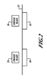
- FIGURE 2 illustrates a partial cross sectional view of the system of FIGURE 1 ;
- FIGURE 3 illustrates a sensor system formed in accordance with an alternate embodiment of the present invention.
- FIGURES 1 and 2 illustrate an example of a Micro ElectroMechanical Systems (MEMS) sensor 20 that measures rate of rotation about two orthogonal axes.
- the sensor 20 includes two tuning fork proof masses 24, 26, a motor charge amplifier 44, a sense charge amplifier 50, a processing device 54, and an output device 56.
- the proof masses 24, 26 are located above a substrate that includes Coriolis sense electrodes 40 and 42, which are sensitive to out-of plane proof mass motions.
- the sensor 20 also includes two in-plane Coriolis sense electrodes 63, which are sensitive to in-plane proof mass motions.
- Motor driver components 60 are electrically connected to drive combs 62.
- the motor charge amplifier 44 is electrically connected to sense combs 64.
- the proof masses 24, 26 are driven to oscillate at resonance in an X direction.
- the proof masses 24, 26 are driven to oscillate out of phase by the motor driver components 60.
- On opposing sides of the proof masses 24, 26 are tines that are interleaved with tines of the drive sense combs 64.
- the motor charge amplifier 44 outputs a motor signal to the processing device that generates motor driver signals that are sent to the motor drive combs 62 via the motor driver component 60 in order to make sure that the proof masses 24, 26 are driven at the mechanical resonant frequency.
- the in-plane Coriolis sense electrodes 63 are asymmetric from the motor drive and drive sense combs 62, 64 of the proof mass 26 in order to allow detection of capacitance change for motion of the proof masses 24, 26 in the Y direction, induced by rotation about the Z axis (the direction perpendicular to the motor motion).
- both proof masses 24, 26 are electrically connected to the charge amplifier 50 for outputting a voltage signal to the processing device 54.
- the outputted voltage signal is received by the processing device 54.
- the voltage signal that is applied to the in-plane Coriolis electrodes 63 is modulated at a first frequency and a voltage signal applied to the out of plane Coriolis electrodes 40 and 42 are modulated at a second frequency that is different than the first frequency.
- the processing device 54 includes demodulators that demodulate both of the modulation frequencies. The modulation frequencies would be far removed from mechanical resonances of the sensor 20.
- the processing device 54 analyzes the demodulated signal to determine if a rate of rotation has occurred about the Z-axis.
- the processing device 54 demodulates the signals received at the second modulation frequency to determine the rate of rotation about the Y-axis.
- the determined rate of rotation values are outputted via the output device 56.
- FIGURE 3 illustrates another example system 70 for sensing rate of rotation about two separate axes.
- the system 70 includes the same motor drive component 60 proof masses 24, 26, electrodes 40a, 42a, and combs 62, 64 as FIGURE 1 .
- the system 70 includes a processing device 74 that receives signals from the electrodes 40a, 42a and from the sense combs 63.
- the proof masses 24, 26 are biased to a predefined voltage, such as ground.
- the separate processing device 54 is two separate devices for determining rate of rotation values for each axis of rotation. The determined rate of rotation values are outputted via an output device 56.
- the embodiments of the invention in which an exclusive property or privilege is claimed are defined as follows:
Landscapes
- Engineering & Computer Science (AREA)
- Physics & Mathematics (AREA)
- General Physics & Mathematics (AREA)
- Radar, Positioning & Navigation (AREA)
- Remote Sensing (AREA)
- Signal Processing (AREA)
- Computer Hardware Design (AREA)
- Microelectronics & Electronic Packaging (AREA)
- Gyroscopes (AREA)
Applications Claiming Priority (1)
| Application Number | Priority Date | Filing Date | Title |
|---|---|---|---|
| US11/747,629 US7703324B2 (en) | 2007-05-11 | 2007-05-11 | MEMS tuning fork gyro sensitive to rate of rotation about two axes |
Publications (3)
| Publication Number | Publication Date |
|---|---|
| EP1990608A2 true EP1990608A2 (de) | 2008-11-12 |
| EP1990608A3 EP1990608A3 (de) | 2014-03-05 |
| EP1990608B1 EP1990608B1 (de) | 2017-04-19 |
Family
ID=39713949
Family Applications (1)
| Application Number | Title | Priority Date | Filing Date |
|---|---|---|---|
| EP08156021.1A Not-in-force EP1990608B1 (de) | 2007-05-11 | 2008-05-09 | Auf Rotationsrate um zwei Achsen sensitiver MEMS-Stimmgabelkreisel |
Country Status (4)
| Country | Link |
|---|---|
| US (1) | US7703324B2 (de) |
| EP (1) | EP1990608B1 (de) |
| JP (1) | JP5346174B2 (de) |
| KR (1) | KR101443068B1 (de) |
Cited By (2)
| Publication number | Priority date | Publication date | Assignee | Title |
|---|---|---|---|---|
| CN103787266A (zh) * | 2012-10-26 | 2014-05-14 | 罗伯特·博世有限公司 | 机械部件、机械系统和用于运行机械部件的方法 |
| CN105606845A (zh) * | 2015-12-23 | 2016-05-25 | 北京航空航天大学 | 一种基于二级微杠杆的双质量块高灵敏度硅微谐振式加速度计结构 |
Families Citing this family (7)
| Publication number | Priority date | Publication date | Assignee | Title |
|---|---|---|---|---|
| US7971483B2 (en) * | 2008-03-28 | 2011-07-05 | Honeywell International Inc. | Systems and methods for acceleration and rotational determination from an out-of-plane MEMS device |
| US7984648B2 (en) * | 2008-04-10 | 2011-07-26 | Honeywell International Inc. | Systems and methods for acceleration and rotational determination from an in-plane and out-of-plane MEMS device |
| DE102010006584B4 (de) * | 2010-02-02 | 2012-09-27 | Northrop Grumman Litef Gmbh | Corioliskreisel mit Korrektureinheiten und Verfahren zur Reduktion des Quadraturbias |
| TWI453371B (zh) | 2011-12-30 | 2014-09-21 | Ind Tech Res Inst | 一種具振盪模組的微機電系統裝置 |
| DE102014202053A1 (de) * | 2014-02-05 | 2015-08-06 | Robert Bosch Gmbh | Sensorvorrichtung und Verfahren zum Betreiben einer Sensorvorrichtung mit mindestens einer seismischen Masse |
| CN106289212B (zh) * | 2016-09-21 | 2023-05-05 | 南京理工大学 | 用于硅微音叉陀螺的集成测控单元 |
| US11220424B2 (en) | 2018-08-09 | 2022-01-11 | Honeywell International Inc. | Methods for increasing aspect ratios in comb structures |
Family Cites Families (10)
| Publication number | Priority date | Publication date | Assignee | Title |
|---|---|---|---|---|
| US5987986A (en) * | 1994-07-29 | 1999-11-23 | Litton Systems, Inc. | Navigation grade micromachined rotation sensor system |
| JP3307130B2 (ja) * | 1994-12-28 | 2002-07-24 | 株式会社村田製作所 | 角速度センサ |
| KR100374803B1 (ko) * | 1995-05-25 | 2003-05-12 | 삼성전자주식회사 | 튜닝포크형자이로스코프 |
| DE19641284C1 (de) * | 1996-10-07 | 1998-05-20 | Inst Mikro Und Informationstec | Drehratensensor mit entkoppelten orthogonalen Primär- und Sekundärschwingungen |
| KR100442823B1 (ko) * | 1997-05-09 | 2004-09-18 | 삼성전자주식회사 | 마이크로자이로스코프 |
| JPH112526A (ja) * | 1997-06-13 | 1999-01-06 | Mitsubishi Electric Corp | 振動型角速度センサ |
| JP2002148047A (ja) * | 2000-11-07 | 2002-05-22 | Murata Mfg Co Ltd | ジャイロ装置 |
| JP2002195832A (ja) * | 2000-12-27 | 2002-07-10 | Fujitsu Media Device Kk | 角速度検出装置および角速度検出方法 |
| US6928872B2 (en) * | 2001-04-27 | 2005-08-16 | Stmicroelectronics S.R.L. | Integrated gyroscope of semiconductor material with at least one sensitive axis in the sensor plane |
| JP2008514968A (ja) * | 2004-09-27 | 2008-05-08 | コンティ テミック マイクロエレクトロニック ゲゼルシャフト ミット ベシュレンクテル ハフツング | 回転速度センサ |
-
2007
- 2007-05-11 US US11/747,629 patent/US7703324B2/en active Active
-
2008
- 2008-05-09 EP EP08156021.1A patent/EP1990608B1/de not_active Not-in-force
- 2008-05-12 JP JP2008124759A patent/JP5346174B2/ja not_active Expired - Fee Related
- 2008-05-13 KR KR1020080043961A patent/KR101443068B1/ko not_active Expired - Fee Related
Cited By (4)
| Publication number | Priority date | Publication date | Assignee | Title |
|---|---|---|---|---|
| CN103787266A (zh) * | 2012-10-26 | 2014-05-14 | 罗伯特·博世有限公司 | 机械部件、机械系统和用于运行机械部件的方法 |
| CN103787266B (zh) * | 2012-10-26 | 2017-01-04 | 罗伯特·博世有限公司 | 机械部件、机械系统和用于运行机械部件的方法 |
| US9593013B2 (en) | 2012-10-26 | 2017-03-14 | Robert Bosch Gmbh | Mechanical component, mechanical system, and method for operating a mechanical component |
| CN105606845A (zh) * | 2015-12-23 | 2016-05-25 | 北京航空航天大学 | 一种基于二级微杠杆的双质量块高灵敏度硅微谐振式加速度计结构 |
Also Published As
| Publication number | Publication date |
|---|---|
| JP5346174B2 (ja) | 2013-11-20 |
| US20080276707A1 (en) | 2008-11-13 |
| US7703324B2 (en) | 2010-04-27 |
| EP1990608A3 (de) | 2014-03-05 |
| KR101443068B1 (ko) | 2014-09-22 |
| JP2008281566A (ja) | 2008-11-20 |
| KR20080100149A (ko) | 2008-11-14 |
| EP1990608B1 (de) | 2017-04-19 |
Similar Documents
| Publication | Publication Date | Title |
|---|---|---|
| EP1990608B1 (de) | Auf Rotationsrate um zwei Achsen sensitiver MEMS-Stimmgabelkreisel | |
| EP2108964B1 (de) | Systeme und Verfahren zur Beschleunigung und Drehbestimmung aus einer MEMS-Vorrichtung innerhalb und außerhalb der Ebene | |
| EP2977722B1 (de) | Schwungmasse-gyroskopsystem und verfahren | |
| EP2236981B1 (de) | Leseschaltung für ein mehrachsiges MEMS-Gyroskop mit hinsichtlich der Bezugsachse geneigten Erkennungsrichtungen und entsprechendes mehrachsiges MEMS-Gyroskop | |
| US10209270B2 (en) | Inertial sensors | |
| JP2008514968A (ja) | 回転速度センサ | |
| JP2012198224A (ja) | 音叉ジャイロスコープ装置を有する2軸ヨーレート検知ユニット | |
| WO2015013827A1 (en) | Mems motion sensor for sub-resonance angular rate sensing | |
| EP3249355B1 (de) | Systeme und verfahren zur bias-unterdrückung in einem nicht degenerierten mems-sensor | |
| US20140116134A1 (en) | Micromechanical structure | |
| WO2016153642A1 (en) | Gyroscope that compensates for fluctuations in sensitivity | |
| EP2786095B1 (de) | Fehlererkennung mithilfe von schrägen wandlern | |
| US20050268716A1 (en) | Built in test for mems vibratory type inertial sensors | |
| JPH02129514A (ja) | 角速度センサー | |
| KR100442823B1 (ko) | 마이크로자이로스코프 | |
| EP4471375A1 (de) | Mikroelektromechanisches gyroskop mit verbesserter vibrationsunterdrückung | |
| Chen et al. | Micromachined bar-structure gyroscope with high Q-factors for both driving and sensing mode at atmospheric pressure | |
| KR101306877B1 (ko) | 내부감지전극을 갖는 튜닝포크형 자이로스코프 | |
| JP2000337886A (ja) | マイクロジャイロスコープ | |
| KR101458837B1 (ko) | 듀얼매스 자이로스코프의 진동 제어방법 | |
| KR20090107932A (ko) | 평면내 및 평면외 mems 장치로부터 가속 및 회전 판단을 위한 시스템 및 방법 | |
| US20190086208A1 (en) | Rotational speed sensor and operation of a rotational speed sensor at various frequencies and in various directions | |
| JP2010181186A (ja) | 加速度と角速度を検出する装置 |
Legal Events
| Date | Code | Title | Description |
|---|---|---|---|
| PUAI | Public reference made under article 153(3) epc to a published international application that has entered the european phase |
Free format text: ORIGINAL CODE: 0009012 |
|
| 17P | Request for examination filed |
Effective date: 20080509 |
|
| AK | Designated contracting states |
Kind code of ref document: A2 Designated state(s): AT BE BG CH CY CZ DE DK EE ES FI FR GB GR HR HU IE IS IT LI LT LU LV MC MT NL NO PL PT RO SE SI SK TR |
|
| AX | Request for extension of the european patent |
Extension state: AL BA MK RS |
|
| REG | Reference to a national code |
Ref country code: DE Ref legal event code: R079 Ref document number: 602008049802 Country of ref document: DE Free format text: PREVIOUS MAIN CLASS: G01C0019560000 Ipc: G01C0019572600 |
|
| PUAL | Search report despatched |
Free format text: ORIGINAL CODE: 0009013 |
|
| AK | Designated contracting states |
Kind code of ref document: A3 Designated state(s): AT BE BG CH CY CZ DE DK EE ES FI FR GB GR HR HU IE IS IT LI LT LU LV MC MT NL NO PL PT RO SE SI SK TR |
|
| AX | Request for extension of the european patent |
Extension state: AL BA MK RS |
|
| RIC1 | Information provided on ipc code assigned before grant |
Ipc: G01C 19/5726 20120101AFI20140129BHEP |
|
| 17Q | First examination report despatched |
Effective date: 20140227 |
|
| 17Q | First examination report despatched |
Effective date: 20140919 |
|
| AKX | Designation fees paid |
Designated state(s): DE FR GB |
|
| RAP1 | Party data changed (applicant data changed or rights of an application transferred) |
Owner name: HONEYWELL INTERNATIONAL INC. |
|
| GRAP | Despatch of communication of intention to grant a patent |
Free format text: ORIGINAL CODE: EPIDOSNIGR1 |
|
| INTG | Intention to grant announced |
Effective date: 20161207 |
|
| RIN1 | Information on inventor provided before grant (corrected) |
Inventor name: SUTTON, MICHAEL S. Inventor name: WEBER, MARK W. |
|
| GRAS | Grant fee paid |
Free format text: ORIGINAL CODE: EPIDOSNIGR3 |
|
| GRAA | (expected) grant |
Free format text: ORIGINAL CODE: 0009210 |
|
| AK | Designated contracting states |
Kind code of ref document: B1 Designated state(s): DE FR GB |
|
| REG | Reference to a national code |
Ref country code: GB Ref legal event code: FG4D |
|
| REG | Reference to a national code |
Ref country code: DE Ref legal event code: R096 Ref document number: 602008049802 Country of ref document: DE |
|
| PGFP | Annual fee paid to national office [announced via postgrant information from national office to epo] |
Ref country code: GR Payment date: 20170427 Year of fee payment: 10 |
|
| REG | Reference to a national code |
Ref country code: DE Ref legal event code: R097 Ref document number: 602008049802 Country of ref document: DE |
|
| PLBE | No opposition filed within time limit |
Free format text: ORIGINAL CODE: 0009261 |
|
| STAA | Information on the status of an ep patent application or granted ep patent |
Free format text: STATUS: NO OPPOSITION FILED WITHIN TIME LIMIT |
|
| REG | Reference to a national code |
Ref country code: FR Ref legal event code: ST Effective date: 20180131 |
|
| 26N | No opposition filed |
Effective date: 20180122 |
|
| PG25 | Lapsed in a contracting state [announced via postgrant information from national office to epo] |
Ref country code: FR Free format text: LAPSE BECAUSE OF NON-PAYMENT OF DUE FEES Effective date: 20170619 |
|
| PGFP | Annual fee paid to national office [announced via postgrant information from national office to epo] |
Ref country code: GB Payment date: 20180530 Year of fee payment: 11 |
|
| REG | Reference to a national code |
Ref country code: DE Ref legal event code: R119 Ref document number: 602008049802 Country of ref document: DE |
|
| PG25 | Lapsed in a contracting state [announced via postgrant information from national office to epo] |
Ref country code: DE Free format text: LAPSE BECAUSE OF NON-PAYMENT OF DUE FEES Effective date: 20181201 |
|
| GBPC | Gb: european patent ceased through non-payment of renewal fee |
Effective date: 20190509 |
|
| PG25 | Lapsed in a contracting state [announced via postgrant information from national office to epo] |
Ref country code: GB Free format text: LAPSE BECAUSE OF NON-PAYMENT OF DUE FEES Effective date: 20190509 |
|
| P01 | Opt-out of the competence of the unified patent court (upc) registered |
Effective date: 20230525 |