EP1990686A1 - Übertragungseinheit und Bilderzeugungsvorrichtung damit - Google Patents
Übertragungseinheit und Bilderzeugungsvorrichtung damit Download PDFInfo
- Publication number
- EP1990686A1 EP1990686A1 EP08155951A EP08155951A EP1990686A1 EP 1990686 A1 EP1990686 A1 EP 1990686A1 EP 08155951 A EP08155951 A EP 08155951A EP 08155951 A EP08155951 A EP 08155951A EP 1990686 A1 EP1990686 A1 EP 1990686A1
- Authority
- EP
- European Patent Office
- Prior art keywords
- transfer
- image
- image forming
- charging
- units
- Prior art date
- Legal status (The legal status is an assumption and is not a legal conclusion. Google has not performed a legal analysis and makes no representation as to the accuracy of the status listed.)
- Granted
Links
- 238000012546 transfer Methods 0.000 title claims abstract description 319
- 239000000969 carrier Substances 0.000 claims abstract description 36
- 239000003086 colorant Substances 0.000 claims abstract description 18
- 238000003825 pressing Methods 0.000 claims description 57
- 238000000034 method Methods 0.000 description 57
- 239000000314 lubricant Substances 0.000 description 32
- 230000008569 process Effects 0.000 description 32
- 230000007423 decrease Effects 0.000 description 13
- 238000005259 measurement Methods 0.000 description 12
- 230000005684 electric field Effects 0.000 description 9
- 230000008859 change Effects 0.000 description 7
- CBENFWSGALASAD-UHFFFAOYSA-N Ozone Chemical compound [O-][O+]=O CBENFWSGALASAD-UHFFFAOYSA-N 0.000 description 6
- 239000002131 composite material Substances 0.000 description 6
- 230000000694 effects Effects 0.000 description 5
- 230000009471 action Effects 0.000 description 4
- 239000011521 glass Substances 0.000 description 4
- 239000002184 metal Substances 0.000 description 4
- 239000007787 solid Substances 0.000 description 4
- 239000000428 dust Substances 0.000 description 3
- 230000005484 gravity Effects 0.000 description 3
- 239000000463 material Substances 0.000 description 3
- 230000009467 reduction Effects 0.000 description 3
- 238000000926 separation method Methods 0.000 description 3
- 229920000459 Nitrile rubber Polymers 0.000 description 2
- 239000000853 adhesive Substances 0.000 description 2
- 230000001070 adhesive effect Effects 0.000 description 2
- 238000004140 cleaning Methods 0.000 description 2
- 230000006835 compression Effects 0.000 description 2
- 238000007906 compression Methods 0.000 description 2
- 239000000470 constituent Substances 0.000 description 2
- 229920001971 elastomer Polymers 0.000 description 2
- 239000005060 rubber Substances 0.000 description 2
- 230000015572 biosynthetic process Effects 0.000 description 1
- 230000000052 comparative effect Effects 0.000 description 1
- 239000012141 concentrate Substances 0.000 description 1
- 238000011109 contamination Methods 0.000 description 1
- 238000013461 design Methods 0.000 description 1
- 230000006866 deterioration Effects 0.000 description 1
- 238000009826 distribution Methods 0.000 description 1
- 230000002708 enhancing effect Effects 0.000 description 1
- 230000007613 environmental effect Effects 0.000 description 1
- 238000012423 maintenance Methods 0.000 description 1
- 238000012986 modification Methods 0.000 description 1
- 230000004048 modification Effects 0.000 description 1
- 238000007788 roughening Methods 0.000 description 1
- 230000003746 surface roughness Effects 0.000 description 1
- 230000001360 synchronised effect Effects 0.000 description 1
- 238000011144 upstream manufacturing Methods 0.000 description 1
Images


Classifications
-
- G—PHYSICS
- G03—PHOTOGRAPHY; CINEMATOGRAPHY; ANALOGOUS TECHNIQUES USING WAVES OTHER THAN OPTICAL WAVES; ELECTROGRAPHY; HOLOGRAPHY
- G03G—ELECTROGRAPHY; ELECTROPHOTOGRAPHY; MAGNETOGRAPHY
- G03G15/00—Apparatus for electrographic processes using a charge pattern
- G03G15/02—Apparatus for electrographic processes using a charge pattern for laying down a uniform charge, e.g. for sensitising; Corona discharge devices
- G03G15/0291—Apparatus for electrographic processes using a charge pattern for laying down a uniform charge, e.g. for sensitising; Corona discharge devices corona discharge devices, e.g. wires, pointed electrodes, means for cleaning the corona discharge device
-
- G—PHYSICS
- G03—PHOTOGRAPHY; CINEMATOGRAPHY; ANALOGOUS TECHNIQUES USING WAVES OTHER THAN OPTICAL WAVES; ELECTROGRAPHY; HOLOGRAPHY
- G03G—ELECTROGRAPHY; ELECTROPHOTOGRAPHY; MAGNETOGRAPHY
- G03G15/00—Apparatus for electrographic processes using a charge pattern
- G03G15/01—Apparatus for electrographic processes using a charge pattern for producing multicoloured copies
- G03G15/0142—Structure of complete machines
- G03G15/0178—Structure of complete machines using more than one reusable electrographic recording member, e.g. one for every monocolour image
- G03G15/0194—Structure of complete machines using more than one reusable electrographic recording member, e.g. one for every monocolour image primary transfer to the final recording medium
-
- G—PHYSICS
- G03—PHOTOGRAPHY; CINEMATOGRAPHY; ANALOGOUS TECHNIQUES USING WAVES OTHER THAN OPTICAL WAVES; ELECTROGRAPHY; HOLOGRAPHY
- G03G—ELECTROGRAPHY; ELECTROPHOTOGRAPHY; MAGNETOGRAPHY
- G03G2215/00—Apparatus for electrophotographic processes
- G03G2215/01—Apparatus for electrophotographic processes for producing multicoloured copies
- G03G2215/0103—Plural electrographic recording members
- G03G2215/0119—Linear arrangement adjacent plural transfer points
- G03G2215/0122—Linear arrangement adjacent plural transfer points primary transfer to an intermediate transfer belt
- G03G2215/0125—Linear arrangement adjacent plural transfer points primary transfer to an intermediate transfer belt the linear arrangement being horizontal or slanted
- G03G2215/0129—Linear arrangement adjacent plural transfer points primary transfer to an intermediate transfer belt the linear arrangement being horizontal or slanted horizontal medium transport path at the secondary transfer
-
- G—PHYSICS
- G03—PHOTOGRAPHY; CINEMATOGRAPHY; ANALOGOUS TECHNIQUES USING WAVES OTHER THAN OPTICAL WAVES; ELECTROGRAPHY; HOLOGRAPHY
- G03G—ELECTROGRAPHY; ELECTROPHOTOGRAPHY; MAGNETOGRAPHY
- G03G2215/00—Apparatus for electrophotographic processes
- G03G2215/02—Arrangements for laying down a uniform charge
- G03G2215/026—Arrangements for laying down a uniform charge by coronas
Definitions
- the present invention relates to an electrophotographic image forming apparatus and a transfer unit used therein.
- Image forming apparatuses are used as copiers, facsimile machines, printers, and multi-functional devices combining several of the foregoing capabilities, including color image forming apparatuses.
- color image forming apparatuses employ various types.
- one type of color image forming apparatus employs a direct transfer method, in which toner images formed on a plurality of image carriers are directly and collectively transferred onto a recording medium.
- another type of color image forming apparatus employs an intermediate or indirect transfer method, in which toner images are primarily and collectively transferred onto an intermediate transfer member and then secondarily transferred onto a recording medium.
- such electrophotographic color image forming apparatus typically charges each image carrier with a charging unit of an image forming unit and emits a light beam from a light source, for example, a laser diode (LD) or light-emitting diode (LED), to write an electrostatic latent image on the surface of each image carrier. Then, such electrophotographic image forming apparatus makes visible the latent image using a developing unit to from a toner image on the surface of each image carrier.
- a light source for example, a laser diode (LD) or light-emitting diode (LED)
- one type of color image forming apparatus employing an intermediate transfer method has a plurality of image forming units that contact an intermediate transfer member, which functions as an image transfer member, at different positions.
- the intermediate transfer member may be, for example, an endless-shaped intermediate transfer belt extending over a plurality of rollers.
- Such image forming apparatus has a plurality of primary transfer units corresponding to the image forming units.
- Each primary transfer unit transfers a toner image, formed on each image carrier, onto the intermediate transfer belt.
- a primary transfer area is formed between each image carrier and the intermediate transfer belt.
- the toner image on each image carrier is transferred onto the intermediate transfer belt by action of a transfer electrical field generated at each primary transfer area.
- such image forming apparatus has a secondary transfer unit by which the toner images on the intermediate transfer member are transferred onto a recoding medium such as a paper sheet. Specifically, a transfer electrical field is generated at a secondary transfer area between the intermediate transfer belt and the recording medium. By action of such transfer electrical field, the toner images on the intermediate transfer belt are transferred onto the recording medium to form a final color image thereon.
- the electrostatic latent images formed on the respective image carriers are developed with charged toners of different colors.
- a transfer bias is applied to the intermediate transfer member, thereby generating the transfer electrical field noted above.
- the toner images on the image carriers are sequentially transferred onto the intermediate transfer member to form a color image.
- Such transfer units need to transfer the toner images onto the intermediate transfer member or recording medium so that its original image is precisely and reliably reproduced before and after the transfer process.
- a transfer process needs to be reliably conducted with a relatively high transfer efficiency.
- such color image forming apparatuses may have a charging member using a corona charging method or a charging member using a contact charging method.
- a corona charging member is an electrifying charger
- a contact charging member is a charging roller.
- a charging member may have discharge electrodes, such as wire electrodes, and shield electrodes surrounding the discharge electrodes.
- Such corona charging member applies high voltages to the discharge electrodes and shield electrodes to generate a corona shower, and charges the surface of a charged body, such as an image carrier, by the corona shower to a certain electric potential.
- a drawback of such corona charging method is that it may generate a relatively large amount of ozone and/or may need a relatively high voltage.
- a charging bias is applied to a charging member in contact with a charged body, so that a surface of the charged body is charged to a certain potential.
- Such contact charging method may be performed by a charging member, which may be, for example, roller-type, fur-brush-type, magnetic-brush-type, or blade-type.
- charging roller In one roller-type charging member (hereinafter “charging roller"), direct-current (DC) bias and alternating-current (AC) bias are superposed one on the other and applied to the charging roller, so that the surface of the charging member is uniformly charged to a certain potential.
- DC direct-current
- AC alternating-current
- the application of AC bias may result in a larger discharge amount than the above-described corona charging member, thereby resulting in damage to an image carrier or photoconductor, for example, curling or roughening a surface of the photoconductor.
- lubricant may be applied to the surface of the photoconductor. Such lubricant may prevent the curling of the surface of the photoconductor, although a portion of the lubricant may adhere to the charging roller, thereby preventing the surface of the photoconductor from being uniformly charged.
- the above-described corona charging method is a non-contact charging method.
- Such non-contact charging method can somewhat retard deterioration of a charging unit due to lubricant or toner, thereby reducing damage to a photoconductor. Accordingly, to prevent damage to the photoconductor, a sufficient amount of lubricant can be applied to the surface of the photoconductor with little consideration of contamination of the charging unit by such lubricant or toner.
- the corona charging member may have disadvantages in ozone generation amount and electrical power consumption compared to the charging roller, it may have advantages in service life compared to the charging roller.
- a proximate charging method has been proposed in which a charging roller is disposed proximate to but not in contact with a photoconductor.
- Such configuration may prevent a reduction in charging performance due to foreign matter attaching to the photoconductor, for example, while reducing the amount of ozone generated by utilizing a charging property similar to that of the contact charging method.
- one type of conventional image forming apparatus combines the two methods, that is, has a plurality of toner-image forming units including both the electrifying charger and the charging roller according to toner color.
- the electrifying charger which has a relatively long service life, may be used in a frequently-used image forming unit for the color black
- the charging roller which has a relatively low ozone generation rate and electrical power consumption, may be used in a less-frequently-used image forming unit for a color other than black.
- Such configuration can reduce the frequency of maintenance operations in the image forming apparatus, thereby facilitating a reduction in the amount of ozone generated and electrical power consumption, which are increasingly demanded in view of environmental concerns.
- such conventional image forming apparatus may also have a plurality of pressing units that press the intermediate transfer member to the surfaces of image carriers at respective primary transfer positions. Applying such pressure to a transfer area between each image carrier and the intermediate transfer member during the primary transfer process can enhance transfer efficiency, thereby preventing occurrences of transfer failures such as white dropout in a transferred image.
- image dropout partial dropout of toner image during the transfer process
- one type of conventional image forming apparatus sets a contacting pressure of a pressing unit within a certain range.
- a contacting pressure at a transfer area on a downstream side in a sheet transfer direction thereof is set lower than a contacting pressure at a transfer area on an upstream side.
- Still another type of conventional image forming apparatus employs different contacting pressures between a transfer nip of black toner and a transfer area on the uppermost stream.
- Still another type of conventional image forming apparatus is a tandem-type image forming apparatus that includes a corona charging member and a contact charging member.
- an image forming apparatus including a transfer unit capable of effectively reducing problems such as low transfer efficiency, image dropout during the transfer process, and patchy irregularity of image-density.
- Exemplary embodiments of the present invention provide a developing unit, process cartridge, image forming method and apparatus capable of preventing failures that may be caused by developer dropping through a gap between a developer carrier and an end portion of a separation member.
- an image forming apparatus includes a plurality of image forming units and a plurality of transfer units.
- the plurality of image forming units has corresponding image carriers and charging units.
- the image forming units form toner images of different colors on the corresponding image carriers.
- the plurality of transfer units are disposed to face the corresponding image carriers to form transfer areas between the transfer units and the image carriers and are configured to press a transfer member, passing through the transfer areas, to the corresponding image carriers to transfer the toner images, formed on the corresponding image carriers, onto the transfer member at the transfer areas.
- the charging units include at least one charging member of corona charging type and at least one charging member of contact charging type.
- the image forming apparatus sets a first transfer condition for the transfer unit(s) corresponding to the image carrier(s) charged by the at least one charging member of corona charging type and a second, separate transfer condition for the transfer unit(s) corresponding to the image carrier(s) charged by the at least one charging member of contact charging type.
- an image forming apparatus in another exemplary embodiment, includes a plurality of image forming units and a plurality of transfer units.
- the plurality of image forming units has corresponding image carriers and charging units.
- the image forming units form toner images of different colors on the corresponding image carriers.
- the plurality of transfer units are disposed to face the corresponding image carriers to form transfer areas between the transfer units and the image carriers and are configured to press a transfer member, passing through the transfer areas, to the corresponding image carriers to transfer the toner images, formed on the corresponding image carriers, onto the transfer member at the transfer areas.
- the charging units include at least one charging member of corona charging type and at least one charging member of proximate charging type.
- the image forming apparatus sets a first transfer condition for the transfer unit(s) corresponding to the image carrier(s) charged by the at least one charging member of corona charging type and a second, separate transfer condition for the transfer unit(s) corresponding to the image carrier(s) charged by the at least one charging member of proximate charging type.
- FIG. 1 is a schematic view illustrating a configuration of an image forming apparatus having a transfer unit according to an exemplary embodiment of the present invention.
- an image forming apparatus 100 is illustrated as an electrophotographic color copier having a plurality of photoconductors arranged in tandem. It should be noted that an image forming apparatus according to an exemplary embodiment of the present invention is not limited to such color copier, and therefore may be a printer, scanner, facsimile machine, multi-functional device, or any other suitable type of image forming apparatus.
- the image forming apparatus 100 has an intermediate transfer belt 10 as a transfer member.
- the image forming apparatus 100 also has a sheet feed table 2 at a bottom portion thereof.
- a copier body 1, scanner 3, and auto document feeder (ADF) 4 are sequentially stacked on top of the sheet feed table 2 from bottom to top.
- the copier body 1 has a transfer device 17 at a substantially middle portion thereof.
- the transfer device 17 includes the intermediate transfer belt 10 having an endless shape.
- the intermediate transfer belt 10 is extended over a driving roller 14, a driven roller 15, and a driven roller 16 and is rotated in a clockwise direction in FIG. 1 .
- a cleaner 19, disposed on the left side of the driven roller 15, cleans residual toner, which remains on a surface of the intermediate transfer belt 10 after image transfer, to prepare for a next image forming operation of the transfer device 17.
- a linear portion of the intermediate transfer belt 10 extending between the driving roller 14 and driven roller 15 may be disposed four process cartridges 8Y, 8M, 8C, and 8K, in that order, along the direction of travel of the intermediate transfer belt 10.
- Above the process cartridges 8Y, 8M, 8C, and 8K is disposed an exposure unit 7.
- the process cartridges 8Y, 8M, 8C, and 8K serve as image forming units to form toner images of yellow, magenta, cyan, and black, respectively.
- the process cartridges 8Y, 8M, 8C, and 8K include photoconductors 40Y, 40M, 40C, and 40K, respectively, serving as image carriers.
- the photoconductors 40Y, 40M, 40C, and 40K each are rotatable in a counterclockwise direction in FIG. 1 .
- photoconductors 40Y, 40M, 40C, and 40K are referred to collectively as "photoconductors 40" when the colors need not to be distinguished. This nomenclature is also applied to other components and units where suitable.
- Around the photoconductors 40Y, 40M, 40C, and 40K are disposed charging units 9Y, 9M, 9C, and 9K, developing units 61Y, 61M, 61C, and 61K, transfer units 18Y, 18M, 18C, and 18K, cleaning units 63Y, 63M, 63C, and 63K, and lubricant applicators 64Y, 64M, 64C, and 64K, respectively.
- the charging units 9Y, 9M, 9C, and 9K, developing unit 61Y, 61M, 61C, and 61K, cleaning units 63Y, 63M, 63C, and 63K, and lubricant applicators 64Y, 64M, 64C, and 64K are mounted on the process cartridges 8Y, 8M, 8C, and 8K, respectively.
- Each charging unit 9 has a charging member and a power supply that applies a charging bias to the charging member.
- the charging units 9Y, 9M, and 9C for yellow, magenta, and cyan may have charging rollers 20Y, 20M, and 20C as adjacent-type charging members, while the charging unit 9K may have an electrifying charger 20K as a transfer-type charging member.
- any suitable type of charging roller may be used as the charging rollers 20Y, 20M, and 20C, and any suitable type of electrifying charger may be used as the electrifying charger 20K.
- the charging rollers 20Y, 20M, and 20C are disposed to have small gaps with respect to respective surfaces of the photoconductors 40Y, 40M, and 40C.
- gaps are preferably set in a range of approximately 0.02 to 0.06 millimeters (mm). If such gaps are smaller than 0.02 mm, each photoconductor may undesirably contact the corresponding charging roller, thereby negating advantages of such non-contact-type charging system.
- the electrifying charger 20K is disposed to have a small gap with respect to the photoconductor 40K.
- the gap is preferably set to 1.5 mm, for example.
- the photoconductors 40Y, 40M, and 40C are charged by adjacent-type charging members, although it should be noted that the photoconductors 40Y, 40M, and 40C may be charged by contact-type charging members.
- the transfer units 18Y, 18M, 18C, and 18K are disposed inside the intermediate transfer belt 10 to face the photoconductors 40Y, 40M, 40C, and 40K, respectively.
- the transfer units 18Y, 18M, 18C, and 18K have primary transfer rollers 62Y, 62M, 62C, and 62K, respectively, that press the corresponding photoconductors 40 via the intermediate transfer belt 10.
- Each transfer unit 18 also has a bias supply that applies a transfer bias to the corresponding primary transfer roller 62.
- Each primary transfer roller 62 contacts the intermediate transfer belt 10 with pressure to form a primary transfer area between the intermediate transfer belt 10 and each photoconductor 40.
- the lubricant applicators 64Y, 64M, 64C, and 64K have substantially identical configurations, and therefore as a representative example the configuration of the lubricant applicator 64Y is described below, with reference to FIG. 2 .
- the lubricant applicator 64Y has an application blade 641Y, a lubricant 642Y, a lubricant application brush 643Y, and a spring 644Y.
- the application blade 641Y and the lubricant application brush 643Y each contact the surface of the photoconductor 40Y.
- the spring 644Y presses the lubricant 642Y against the lubricant application brush 643Y.
- rotation of the lubricant application brush 643Y causes a desired amount of the lubricant 642Y to adhere to the lubricant application brush 643Y.
- the lubricant application brush 643Y while rotating, contacts the photoconductor 40Y and thus applies the lubricant 642Y to the surface of the photoconductor 40Y. Then, the lubricant blade 641Y spreads the lubricant 642Y in a layer of substantially uniform thickness over the photoconductor 40Y.
- a secondary transfer unit 22 is disposed below the intermediate transfer belt 10.
- the secondary transfer unit 22 is a roller member that contacts the driven roller 16 with pressure via the intermediate transfer belt 10.
- a secondary transfer area is formed at such contact area between the secondary transfer unit 22 and the intermediate transfer belt 10.
- sheet a recording medium
- the secondary transfer unit 22 is described as a roller-type charger, it should be noted that alternatively such secondary transfer unit may be a non-contact-type charger.
- a sheet reversing unit 28 that turns a sheet upside down when forming images on both faces of the sheet in duplex printing or copying.
- the image forming apparatus 100 also has a fixing device 25 that fixes the toner images on the sheet.
- the fixing device 25 is disposed on a downstream side in a sheet conveyance direction of the secondary transfer unit 22.
- a pressure roller 27 contacts a fixing belt 26 with pressure.
- a transfer belt 24 extending between a pair of rollers 23a and 23b conveys the sheet to the fixing device 25.
- an original document when conducting simplex color copying, an original document may be set on a document tray 30 of the auto document feeder 40.
- such original document may be manually set on a contact glass 32 of the scanner 3 by opening the auto document feeder 4 and then be pressed against the contact glass 32 by closing the auto document feeder 4.
- a user may press a start button to automatically feed the original document to the contact glass 32.
- the scanner 3 is quickly activated, and a first carriage 33 and second carriage 34 start scanning.
- a light beam emitted from a light source of the first carriage 33 is reflected approximately 180 degrees by a pair of mirrors of the second carriage 34.
- the reflected light beam passes through a focus lens 35 and enters a scanning sensor 36.
- the content of the original document is scanned.
- the sheet feed table 2 has a plurality of sheet cassettes 44 in a paper bank 43.
- a corresponding sheet feed roller 42 of the selected sheet cassette 44 is rotated to pick up sheets from the selected sheet cassette 44.
- the sheets are separated one by one by a separation roller 47 and are transported to a feed path 46. Further, each sheet is transported by a transport roller 47 to a feed path 48 of the copier body 1 and is abutted against a registration roller 49 to temporarily stop.
- sheets loaded on a manual feed tray 51 are picked up by rotation of a feed roller 50 and are separated by a separation roller 52 one by one into a manual feed path 53. Each sheet is abutted against the registration roller 49 to temporarily stop.
- rotation of the registration roller 49 is started at a timing synchronized with a timing at which the composite color image on the intermediate transfer belt 10 reaches the registration roller 49.
- the registration roller 49 sends the sheet, temporarily stopped, to the secondary transfer area between the intermediate transfer belt 10 and the secondary transfer unit 22, and then the composite color image is transferred by the secondary transfer unit 22 onto the sheet.
- the sheet having the composite color image is forwarded by the secondary transfer unit 22 and the transfer belt 24 to the fixing device 25.
- the composite color image is fixed by heat and pressure on the sheet.
- the sheet is guided by a switching member 55 to an ejection side, for example, and is ejected by an ejection roller 56 to a stack tray 57.
- the sheet having the composite color image on its front face is guided by the switching member 55 to the sheet reversing unit 28.
- the sheet is turned upside down in the sheet reversing unit 28, the sheet is sent back to the secondary transfer area again.
- the sheet is ejected by the ejection roller 56 to the stack tray 57.
- the transfer device 17 has the transfer units 18Y, 18M, 18C, and 18K and the secondary transfer unit 22.
- the transfer device 17 may have a configuration in which, when forming a single-color toner image, for example, black toner image, the driven rollers 15 and 16 are lowered to separate the photoconductors 40Y, 40M, and 40C from the intermediate transfer belt 10.
- an image forming apparatus may be a single-drum-type image forming apparatus having only one photoconductor, for example.
- an image forming apparatus forms a black toner image first, and then forms other colors only when multi-color image formation is needed.
- the registration roller 49 may be connected to ground so that a bias is applied to the registration roller 49 to remove paper dust.
- a bias is applied to the registration roller 49 by a conductive rubber roller, which, for example, has a diameter of 18 mm and a surface covered with a conductive nitrile butadiene rubber (NBR) having a thickness of 1 mm
- NBR conductive nitrile butadiene rubber
- the volume resistance of the rubber material may become approximately 109 ⁇ cm.
- a voltage of approximately minus 800V may be applied to the front face of the sheet onto which toner is transferred while a voltage of approximately plus 200V may be applied to the back face of the sheet.
- the registration roller 49 is allowed to be connected to ground.
- a DC (direct-current) bias is used as the applied voltage, although it should be noted that an AC (alternative-current) bias including a DC offset component may be used as the applied voltage, thereby allowing the sheet to be more uniformly charged.
- the surface of the sheet is slightly negatively charged.
- conditions of the transfer process may differ from those of the case in which such bias is not applied to the registration roller 49. Accordingly, when such bias is applied to the registration roller 49, the transfer conditions may be modified.
- the amount of lubricant 642 applied to each of the photoconductors 40Y, 40M, and 40C is set to approximately 150 mg per kilometer of traveling distance of each photoconductor, while the amount of lubricant 642 applied to the photoconductor 40K is set to approximately 50 mg per kilometer of traveling distance of the photoconductor 40K.
- Such application amounts are preferable from viewpoints of, for example, its possible damage to the photoconductors 40 and adhesion of lubricant to the charging members.
- the surface friction coefficient of the photoconductor 40K charged by the electrifying charger 20K is set to a relatively small value of 0.08, while the surface friction coefficient of each of the photoconductors 40Y, 40M, and 40K charged by the electrifying chargers 20Y, 20M, and 20C is set to a relatively large value of 0.11.
- the surface friction coefficient ⁇ of each photoconductor 40 is measured by an Euler belt method.
- an A4-size plain paper sheet produced by Ricoh Company, Ltd. under the product code TYPE 6200 may be used to prepare a measurement sheet.
- the plain sheet is cut down to measurement sheets having a size of 297 mm x 30 mm, and a middle portion of each measurement sheet is wrapped over an approximately 90-degree angular range in a circumferential direction of each photoconductor 40.
- a weight of 100 g (0.98 N) is attached to one end portion of the measurement sheet in its wrapping direction, while a digital push-pull gage is attached to the other end portion thereof.
- the linear velocity Vs1 of each photoconductor 40 and the linear velocity Vs2 of the intermediate transfer belt 10 are used as the transfer conditions.
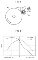
- FIG. 3 illustrates a change in score on image dropout during the transfer process depending on a change in the linear velocity difference between Vs1 and Vs2.
- the vertical axis represents the score on image dropout observed during the intermediate transfer process
- the horizontal axis represents the linear velocity difference between Vs1 and Vs2.
- a solid curve “BLACK” represents the score of the photoconductor 40K for black on the image dropout during the intermediate transfer process.
- a dashed curve “CYAN” represents the score of the photoconductor 40C for cyan on the image dropout during the intermediate transfer process.
- Results of the measurement are scored on a scale of 1 to 5. A score of 1 indicates the worst while a score of 5 is the best, while a score of 4 or greater is considered acceptable.
- the linear velocity difference is determined based on the rotation speed of the intermediate transfer belt 10. Specifically, when the rotation speed of the photoconductor 40 is higher than that of the intermediate transfer belt 10, the linear velocity difference is expressed as a negative value. By contrast, when the rotation speed of the photoconductor 40 is lower than that of the intermediate transfer belt 10, the linear velocity difference is expressed as a positive value.
- the highest score on the image dropout is obtained when the linear velocity difference is approximately zero. Further, as the linear velocity difference deviates from zero in either the positive or negative directions, the score on image dropout decreases.
- the optimal value of the linear velocity difference with respect to the score on image dropout is also different between the photoconductors 40. Accordingly, when the surface friction coefficient of a photoconductor is relatively small, preferably the linear velocity difference is set to a negative value, thereby resulting in an excellent image without image dropout during transfer. Alternatively, when the surface friction coefficient of a photoconductor is relatively large, preferably the linear velocity difference is set to zero, thereby resulting in such an excellent image.
- the linear velocity difference between the photoconductor 40K having the relatively small surface friction coefficient and each of the photoconductor 40Y, 40M, and 40C having the relatively large surface friction coefficient is set to appropriate values based on such measurement results.
- the pressing forces of the primary transfer rollers 62Y, 62M, 62C, and 62K against the photoconductors 40Y, 40M, 40C, and 40K are used as the transfer conditions.
- FIG. 4 illustrates a change in the score on image dropout during the transfer process depending on a change in the pressing force.
- the vertical axis represents the score on image dropout observed during the transfer process
- the horizontal axis represents the pressing force of the primary transfer rollers against the photoconductors.
- a solid curve “BLACK” represents the score of the photoconductor 40K for black on the image dropout during the intermediate transfer process.
- a dashed curve “CYAN” represents the score of the photoconductor 40C for the cyan color on the image dropout during the transfer process.
- the score on image dropout also decreases.
- One possible cause of such tendency is that, when the pressing force of the primary transfer roller 62 decreases, the pressure against the photoconductor 40 and the intermediate transfer belt 10 also decreases. Consequently, a sufficient level of transfer pressure may not be generated, thereby resulting in image dropout during the transfer process.
- toner can easily detach from the surface of the photoconductor 40K. Accordingly, even when the pressing force of the primary transfer roller 62K decreases to some extent, black toner can be appropriately transferred by action of the electrical field generated at the transfer area. Thus, a preferable result of score 4 or greater can be obtained for the photoconductor 40K.
- an increase in the pressing force may result in a decrease in the score on image dropout during the transfer process.
- Such pressing force may concentrate on a portion of toner between each photoconductor 40 and the intermediate transfer belt 10, thereby resulting in image dropout during the transfer process.
- Such image dropout may be similarly observed in the other photoconductors 40Y and 40M. Accordingly, a preferable range of the pressing force with respect to the image dropout may differ between the electrifying charger and the charging roller, or may vary depending on the friction coefficient of each photoconductor 40.
- FIG. 5 illustrates a relation between the pressing force of the primary transfer roller against the photoconductor and the image-density irregularity.
- the vertical axis represents the score on irregularity in image density
- the horizontal axis represents the pressing force of the primary transfer roller against the photoconductor.
- a solid curve “BLACK” represents a change in the score on image-density irregularity observed when the pressing force of the primary transfer roller 62K against the photoconductor 40K for black varies.
- a dashed curve “CYAN 1” represents a change in the score on image-density irregularity observed when the pressing force of the primary transfer roller 62C against the photoconductor 40C for cyan varies.
- a dash-single-dot curve “CYAN 2” represents a change in the score on image-density irregularity observed when the pressing force of the primary transfer roller 62C against the photoconductor 40K for black varies.
- a higher score indicates a better state with respect to the image-density irregularity of a resultant image.
- a score of four or greater is considered acceptable.
- dashed-and-dot curve "CYAN 2" of FIG. 5 suggests that, even when only the pressing force of the primary transfer roller 62K decreases, the score on image-density irregularity for other color toner (here, cyan) as well as black toner increases.
- the pressing force against the intermediate transfer belt 10 may temporarily decrease, thereby improving the score on image-density irregularity. Accordingly, a decrease in the pressing force of the primary transfer roller 62K against the photoconductor 40K may improve images of all four colors with respect to the image-density irregularity.
- the optimal range of the pressing force is different between the electrifying charger 20K and each of the charging rollers 20Y, 20M, and 20C. Accordingly, setting separate optimal ranges of the pressing force for the electrifying charger 20K and each of the charging rollers 20Y, 20M, and 20C may improve the scores on both image dropout during transfer and image-density irregularity.
- the pressing force needs to be set in a preferable range so that a resultant image has a score of four or greater on both the image dropout and image-density irregularity.
- a preferable range is relatively wide compared to when using the charging rollers 20Y, 20M, and 20C.
- the pressing force may be set to 23 N/m, for example.
- the pressing force has some effect on the scores on image-density irregularity of toner images of the colors other than black. Accordingly, the pressing force is set to a relatively small value of 17 N/m, for example, in such preferable range as illustrated in FIG. 4 or 5 . Such configuration can improve image-density irregularity of all color toner images while reducing the image dropout during the transfer process.
- circles in FIGS. 4 and 5 represent optimal pressing forces for black and cyan.
- the transfer member is described as a belt-shaped intermediate transfer member, i.e., the intermediate transfer belt 10.
- the transfer member may be a sheet carried on a transfer convey belt.
- different charging methods may lead to a difference in surface friction coefficient between photoconductors, thereby resulting in a reduction in transfer efficiency and occurrence of white patches.
- the primary transfer unit is described as a roller member. It should be noted that the primary transfer unit is not limited to such roller member and may be a brush or blade member.
- the pressing force may be adjusted by changing the thickness, length, or hardness of the brush member, or the intrusion amount of the brush member to the intermediate transfer belt 10.
- the pressing force may be adjusted by changing the thickness, length, or hardness of the blade member, or the intrusion amount of the blade member to the intermediate transfer belt 10.
- the pressing force of such primary transfer unit against the photoconductor 40K is preferably in a range of 15 to 30 N/m.
- the pressing force of the primary transfer unit against each of the photoconductors 40Y, 40M, and 40C is preferably in a range of 21 to 28 N/m.
- the pressing force of the primary transfer unit is preferably smaller, more preferably 23 N/m.
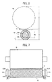
- primary transfer rollers 62Y, 62M, 62C, and 62K which function as the primary transfer units, have substantially identical structures, and therefore are referred to collectively as "primary transfer roller(s) 62" below.
- the primary transfer roller 62 includes a core metal 62a and a cylindrical member 62b of sponge type, for example, around the core metal 62a.
- the diameter "R” of the photoconductor 40 is set to 60 mm
- the diameter "R1” of the primary transfer roller 62 is set to 16 mm
- the diameter "R2" of the core metal 62a is set to 10 mm
- the thickness "t” of the sponge member 62b is set to 3 mm
- the hardness of the sponge 62b is set to Asker C-45°, which is preferably in a range of 40° to 60°.
- the pressing force of the primary transfer roller 62 is generated by bearings 621A and 621B and compression coil springs 622A and 622B.
- the pressing force is expressed by (F+W)/L or (F-W)/L, where "F” represents pressing force of the compression coil springs 622A and 622B, "W” represents a weight of the primary transfer roller 62, and "L” represents a length of the primary transfer roller 62 in a long direction.
- the weight of the primary transfer roller 62 is added to or subtracted from the pressing force "F".
- the direction of the pressing force may be opposite to the direction of the force of gravity as indicated by arrows in FIG. 7 .
- the weight "W” of the primary transfer roller 62 acts in such a direction as to reduce the pressing force to the photoconductor 40. Therefore, the weight of the primary transfer roller 62 is subtracted from the force of gravity.
- nip width "N1" is a length of the transfer area formed between the photoconductor 40 and the intermediate transfer belt 10 in a direction of travel of the intermediate transfer belt 10.
- a variation of the nip width "N1" is smaller than when the intermediate transfer belt 10 has a relatively small contact area with the photoconductor 40.
- variations in transfer electrical-field distribution and in friction resistance applied to the photoconductor 40 which are caused by the variation in the pressing force, become smaller.
- the primary transfer unit is a hard-metal roller member, the variation in the pressing force may have little effect on the nip width "N1", thereby enhancing the stability of the nip width "N1".
- Exemplary embodiments of the present disclosure are not limited to the above-described exemplary embodiments and may be any suitable type of image forming apparatus having a transfer units capable of changing a transfer condition based on a difference in surface friction coefficient between photoconductors. Accordingly, if different types of transfer members, for example, a transfer belt and a sheet, have an identical friction coefficient, similar results can be obtained with such different types of transfer members. Accordingly, such exemplary embodiments are applicable to, for example, known direct-transfer-type image forming apparatus having a plurality of photoconductors arranged in a tandem manner.
Landscapes
- Physics & Mathematics (AREA)
- Engineering & Computer Science (AREA)
- Plasma & Fusion (AREA)
- General Physics & Mathematics (AREA)
- Electrostatic Charge, Transfer And Separation In Electrography (AREA)
- Color Electrophotography (AREA)
Applications Claiming Priority (1)
| Application Number | Priority Date | Filing Date | Title |
|---|---|---|---|
| JP2007127055A JP5277563B2 (ja) | 2007-05-11 | 2007-05-11 | 転写装置及び画像形成装置 |
Publications (2)
| Publication Number | Publication Date |
|---|---|
| EP1990686A1 true EP1990686A1 (de) | 2008-11-12 |
| EP1990686B1 EP1990686B1 (de) | 2014-11-19 |
Family
ID=39620276
Family Applications (1)
| Application Number | Title | Priority Date | Filing Date |
|---|---|---|---|
| EP08155951.0A Ceased EP1990686B1 (de) | 2007-05-11 | 2008-05-09 | Übertragungseinheit und Bilderzeugungsvorrichtung damit |
Country Status (3)
| Country | Link |
|---|---|
| US (1) | US7813662B2 (de) |
| EP (1) | EP1990686B1 (de) |
| JP (1) | JP5277563B2 (de) |
Families Citing this family (8)
| Publication number | Priority date | Publication date | Assignee | Title |
|---|---|---|---|---|
| JP4775777B2 (ja) * | 2009-02-20 | 2011-09-21 | 富士ゼロックス株式会社 | 画像形成装置 |
| JP5459612B2 (ja) * | 2009-04-16 | 2014-04-02 | 株式会社リコー | 画像形成装置 |
| JP2011232729A (ja) | 2010-04-09 | 2011-11-17 | Ricoh Co Ltd | 画像形成装置 |
| JP5888587B2 (ja) | 2011-03-07 | 2016-03-22 | 株式会社リコー | 画像形成装置 |
| JP5955123B2 (ja) * | 2012-06-21 | 2016-07-20 | キヤノン株式会社 | 画像形成装置 |
| US9152090B2 (en) | 2012-07-20 | 2015-10-06 | Ricoh Company, Limited | Image forming apparatus that suppresses deterioration in image quality |
| US9316954B2 (en) | 2012-09-27 | 2016-04-19 | Ricoh Company, Ltd. | Image forming apparatus |
| JP7725937B2 (ja) * | 2021-08-25 | 2025-08-20 | 富士フイルムビジネスイノベーション株式会社 | 画像形成装置 |
Citations (3)
| Publication number | Priority date | Publication date | Assignee | Title |
|---|---|---|---|---|
| JP2001051467A (ja) | 1999-08-06 | 2001-02-23 | Fuji Xerox Co Ltd | カラー画像形成装置 |
| JP2003107853A (ja) | 2001-10-01 | 2003-04-09 | Canon Inc | 帯電装置及び画像形成装置 |
| EP1903406A2 (de) | 2006-09-19 | 2008-03-26 | Ricoh Company, Ltd. | Bilderzeugungseinheit, Prozesskartusche und Bilderzeugungsvorrichtung |
Family Cites Families (19)
| Publication number | Priority date | Publication date | Assignee | Title |
|---|---|---|---|---|
| JPH05307279A (ja) | 1991-03-25 | 1993-11-19 | Katsuragawa Electric Co Ltd | 帯電方法 |
| JPH06202430A (ja) | 1992-12-28 | 1994-07-22 | Canon Inc | 画像形成装置 |
| JPH07301973A (ja) | 1994-04-28 | 1995-11-14 | Canon Inc | 画像形成装置 |
| US5752137A (en) * | 1995-06-09 | 1998-05-12 | Konica Corporation | Multi-color image forming apparatus having a plurality of detachable units |
| JP2001125392A (ja) * | 1999-10-25 | 2001-05-11 | Fuji Xerox Co Ltd | 画像形成装置 |
| US6160980A (en) * | 1999-11-10 | 2000-12-12 | Ziegelmuller; Francisco Luiz | Method and apparatus for reducing contamination of a tackdown, capture or transfer roller on a spliced photoconductor or transport web |
| JP2002014515A (ja) | 2000-06-28 | 2002-01-18 | Ricoh Co Ltd | 画像形成装置及び該装置に用いるベルト装置 |
| JP2002162804A (ja) * | 2000-11-27 | 2002-06-07 | Canon Inc | 画像形成装置 |
| JP2003066683A (ja) * | 2001-08-24 | 2003-03-05 | Fuji Xerox Co Ltd | カラー用画像形成装置 |
| EP1324139A3 (de) * | 2001-12-06 | 2003-10-22 | Ricoh Company, Ltd. | Elektrophotographischer Photoleiter, Verfahrenskassette, Bilderzeugungsgerät, sowie Verfahren zur Bildherstellung |
| JP2004264792A (ja) | 2002-10-10 | 2004-09-24 | Sharp Corp | 画像形成装置 |
| EP1424608B1 (de) * | 2002-11-05 | 2015-07-22 | Ricoh Company, Ltd. | Farbbilderzeugungsgerät |
| JP4350367B2 (ja) * | 2002-12-24 | 2009-10-21 | キヤノン株式会社 | 画像形成装置 |
| JP4778671B2 (ja) * | 2003-07-02 | 2011-09-21 | 株式会社リコー | 画像形成装置に用いる転写用部材の抵抗変化判定方法 |
| JP2005024936A (ja) * | 2003-07-03 | 2005-01-27 | Canon Inc | 画像形成装置 |
| US7162179B2 (en) * | 2004-05-17 | 2007-01-09 | Ricoh Company, Limited | Image forming apparatus |
| JP2007140085A (ja) * | 2005-11-18 | 2007-06-07 | Ricoh Co Ltd | 潤滑剤供給装置及び画像形成装置 |
| JP4772590B2 (ja) * | 2006-05-30 | 2011-09-14 | 株式会社リコー | 画像形成装置 |
| US8731420B2 (en) * | 2006-10-12 | 2014-05-20 | Ricoh Company, Limited | Image forming apparatus and methods of setting transfer current and forming image |
-
2007
- 2007-05-11 JP JP2007127055A patent/JP5277563B2/ja active Active
-
2008
- 2008-05-09 EP EP08155951.0A patent/EP1990686B1/de not_active Ceased
- 2008-05-12 US US12/119,050 patent/US7813662B2/en active Active
Patent Citations (3)
| Publication number | Priority date | Publication date | Assignee | Title |
|---|---|---|---|---|
| JP2001051467A (ja) | 1999-08-06 | 2001-02-23 | Fuji Xerox Co Ltd | カラー画像形成装置 |
| JP2003107853A (ja) | 2001-10-01 | 2003-04-09 | Canon Inc | 帯電装置及び画像形成装置 |
| EP1903406A2 (de) | 2006-09-19 | 2008-03-26 | Ricoh Company, Ltd. | Bilderzeugungseinheit, Prozesskartusche und Bilderzeugungsvorrichtung |
Also Published As
| Publication number | Publication date |
|---|---|
| EP1990686B1 (de) | 2014-11-19 |
| JP2008281856A (ja) | 2008-11-20 |
| US20080279589A1 (en) | 2008-11-13 |
| US7813662B2 (en) | 2010-10-12 |
| JP5277563B2 (ja) | 2013-08-28 |
Similar Documents
| Publication | Publication Date | Title |
|---|---|---|
| US8041243B2 (en) | Image forming apparatus and image forming method capable of effectively transferring toner images | |
| EP1990686B1 (de) | Übertragungseinheit und Bilderzeugungsvorrichtung damit | |
| US8977153B2 (en) | Image forming apparatus which uses an AC voltage and/or a DC voltage at a transfer nip depending on a surface roughness of a recording sheet | |
| US9046853B2 (en) | Image forming apparatus | |
| US7174124B2 (en) | Tandem color image forming apparatus with an image transfer belt and backup roller | |
| US9599937B2 (en) | Image forming apparatus and method of separating recording medium | |
| US20090324270A1 (en) | Image forming apparatus and control method therefor | |
| US9395656B2 (en) | Transfer unit and image forming apparatus employing the transfer unit | |
| US9846396B2 (en) | Transfer device and image forming apparatus incorporating same | |
| US20180046128A1 (en) | Cleaning device, process cartridge incorporating the cleaning device, and image forming apparatus incorporating the cleaning device | |
| US20140153958A1 (en) | Sealing assembly, developing device, process unit, and image forming apparatus incorporating same | |
| US20160195830A1 (en) | Process cartridge, image forming apparatus with process cartridge, and method of forming image by using image forming apparatus with process cartridge | |
| US8867971B2 (en) | Developer regulator, development device, and image forming apparatus incorporating same | |
| JP5382492B2 (ja) | 画像形成装置 | |
| EP3502781B1 (de) | Bildtragendes element und bilderzeugungsvorrichtung | |
| JP4820687B2 (ja) | カラー画像形成装置 | |
| US11073775B2 (en) | Transfer device and image forming apparatus incorporating same | |
| JP5915097B2 (ja) | 転写装置及び画像形成装置 | |
| JP4820686B2 (ja) | カラー画像形成装置 | |
| JP3940654B2 (ja) | 定着装置と画像形成装置 | |
| JP2019008276A (ja) | プロセスカートリッジ、及び、画像形成装置 | |
| JP2016180905A (ja) | 転写部材および画像形成装置 | |
| JP2024057158A (ja) | 画像形成装置 | |
| JP2009098170A (ja) | 画像形成装置 | |
| JP2009134226A (ja) | 画像形成装置 |
Legal Events
| Date | Code | Title | Description |
|---|---|---|---|
| PUAI | Public reference made under article 153(3) epc to a published international application that has entered the european phase |
Free format text: ORIGINAL CODE: 0009012 |
|
| AK | Designated contracting states |
Kind code of ref document: A1 Designated state(s): AT BE BG CH CY CZ DE DK EE ES FI FR GB GR HR HU IE IS IT LI LT LU LV MC MT NL NO PL PT RO SE SI SK TR |
|
| AX | Request for extension of the european patent |
Extension state: AL BA MK RS |
|
| 17P | Request for examination filed |
Effective date: 20090115 |
|
| AKX | Designation fees paid |
Designated state(s): DE FR GB |
|
| GRAP | Despatch of communication of intention to grant a patent |
Free format text: ORIGINAL CODE: EPIDOSNIGR1 |
|
| INTG | Intention to grant announced |
Effective date: 20140716 |
|
| GRAS | Grant fee paid |
Free format text: ORIGINAL CODE: EPIDOSNIGR3 |
|
| GRAA | (expected) grant |
Free format text: ORIGINAL CODE: 0009210 |
|
| AK | Designated contracting states |
Kind code of ref document: B1 Designated state(s): DE FR GB |
|
| REG | Reference to a national code |
Ref country code: GB Ref legal event code: FG4D |
|
| REG | Reference to a national code |
Ref country code: DE Ref legal event code: R096 Ref document number: 602008035422 Country of ref document: DE Effective date: 20141231 |
|
| REG | Reference to a national code |
Ref country code: DE Ref legal event code: R097 Ref document number: 602008035422 Country of ref document: DE |
|
| PLBE | No opposition filed within time limit |
Free format text: ORIGINAL CODE: 0009261 |
|
| STAA | Information on the status of an ep patent application or granted ep patent |
Free format text: STATUS: NO OPPOSITION FILED WITHIN TIME LIMIT |
|
| 26N | No opposition filed |
Effective date: 20150820 |
|
| REG | Reference to a national code |
Ref country code: FR Ref legal event code: PLFP Year of fee payment: 9 |
|
| REG | Reference to a national code |
Ref country code: FR Ref legal event code: PLFP Year of fee payment: 10 |
|
| REG | Reference to a national code |
Ref country code: FR Ref legal event code: PLFP Year of fee payment: 11 |
|
| PGFP | Annual fee paid to national office [announced via postgrant information from national office to epo] |
Ref country code: DE Payment date: 20180522 Year of fee payment: 11 |
|
| PGFP | Annual fee paid to national office [announced via postgrant information from national office to epo] |
Ref country code: FR Payment date: 20180522 Year of fee payment: 11 |
|
| PGFP | Annual fee paid to national office [announced via postgrant information from national office to epo] |
Ref country code: GB Payment date: 20180518 Year of fee payment: 11 |
|
| REG | Reference to a national code |
Ref country code: DE Ref legal event code: R119 Ref document number: 602008035422 Country of ref document: DE |
|
| GBPC | Gb: european patent ceased through non-payment of renewal fee |
Effective date: 20190509 |
|
| PG25 | Lapsed in a contracting state [announced via postgrant information from national office to epo] |
Ref country code: GB Free format text: LAPSE BECAUSE OF NON-PAYMENT OF DUE FEES Effective date: 20190509 Ref country code: DE Free format text: LAPSE BECAUSE OF NON-PAYMENT OF DUE FEES Effective date: 20191203 |
|
| PG25 | Lapsed in a contracting state [announced via postgrant information from national office to epo] |
Ref country code: FR Free format text: LAPSE BECAUSE OF NON-PAYMENT OF DUE FEES Effective date: 20190531 |