EP1903406A2 - Bilderzeugungseinheit, Prozesskartusche und Bilderzeugungsvorrichtung - Google Patents
Bilderzeugungseinheit, Prozesskartusche und Bilderzeugungsvorrichtung Download PDFInfo
- Publication number
- EP1903406A2 EP1903406A2 EP07115683A EP07115683A EP1903406A2 EP 1903406 A2 EP1903406 A2 EP 1903406A2 EP 07115683 A EP07115683 A EP 07115683A EP 07115683 A EP07115683 A EP 07115683A EP 1903406 A2 EP1903406 A2 EP 1903406A2
- Authority
- EP
- European Patent Office
- Prior art keywords
- image forming
- photosensitive drum
- unit
- charging unit
- toner
- Prior art date
- Legal status (The legal status is an assumption and is not a legal conclusion. Google has not performed a legal analysis and makes no representation as to the accuracy of the status listed.)
- Granted
Links
Images

Classifications
-
- G—PHYSICS
- G03—PHOTOGRAPHY; CINEMATOGRAPHY; ANALOGOUS TECHNIQUES USING WAVES OTHER THAN OPTICAL WAVES; ELECTROGRAPHY; HOLOGRAPHY
- G03G—ELECTROGRAPHY; ELECTROPHOTOGRAPHY; MAGNETOGRAPHY
- G03G15/00—Apparatus for electrographic processes using a charge pattern
- G03G15/02—Apparatus for electrographic processes using a charge pattern for laying down a uniform charge, e.g. for sensitising; Corona discharge devices
- G03G15/0291—Apparatus for electrographic processes using a charge pattern for laying down a uniform charge, e.g. for sensitising; Corona discharge devices corona discharge devices, e.g. wires, pointed electrodes, means for cleaning the corona discharge device
-
- G—PHYSICS
- G03—PHOTOGRAPHY; CINEMATOGRAPHY; ANALOGOUS TECHNIQUES USING WAVES OTHER THAN OPTICAL WAVES; ELECTROGRAPHY; HOLOGRAPHY
- G03G—ELECTROGRAPHY; ELECTROPHOTOGRAPHY; MAGNETOGRAPHY
- G03G15/00—Apparatus for electrographic processes using a charge pattern
- G03G15/01—Apparatus for electrographic processes using a charge pattern for producing multicoloured copies
- G03G15/0142—Structure of complete machines
- G03G15/0178—Structure of complete machines using more than one reusable electrographic recording member, e.g. one for every monocolour image
- G03G15/0194—Structure of complete machines using more than one reusable electrographic recording member, e.g. one for every monocolour image primary transfer to the final recording medium
-
- G—PHYSICS
- G03—PHOTOGRAPHY; CINEMATOGRAPHY; ANALOGOUS TECHNIQUES USING WAVES OTHER THAN OPTICAL WAVES; ELECTROGRAPHY; HOLOGRAPHY
- G03G—ELECTROGRAPHY; ELECTROPHOTOGRAPHY; MAGNETOGRAPHY
- G03G2215/00—Apparatus for electrophotographic processes
- G03G2215/01—Apparatus for electrophotographic processes for producing multicoloured copies
- G03G2215/0103—Plural electrographic recording members
- G03G2215/0119—Linear arrangement adjacent plural transfer points
-
- G—PHYSICS
- G03—PHOTOGRAPHY; CINEMATOGRAPHY; ANALOGOUS TECHNIQUES USING WAVES OTHER THAN OPTICAL WAVES; ELECTROGRAPHY; HOLOGRAPHY
- G03G—ELECTROGRAPHY; ELECTROPHOTOGRAPHY; MAGNETOGRAPHY
- G03G2215/00—Apparatus for electrophotographic processes
- G03G2215/02—Arrangements for laying down a uniform charge
- G03G2215/026—Arrangements for laying down a uniform charge by coronas
-
- G—PHYSICS
- G03—PHOTOGRAPHY; CINEMATOGRAPHY; ANALOGOUS TECHNIQUES USING WAVES OTHER THAN OPTICAL WAVES; ELECTROGRAPHY; HOLOGRAPHY
- G03G—ELECTROGRAPHY; ELECTROPHOTOGRAPHY; MAGNETOGRAPHY
- G03G2215/00—Apparatus for electrophotographic processes
- G03G2215/02—Arrangements for laying down a uniform charge
- G03G2215/026—Arrangements for laying down a uniform charge by coronas
- G03G2215/027—Arrangements for laying down a uniform charge by coronas using wires
Definitions
- the present invention generally relates to an image forming apparatus, and specifically relates to a charging mechanism for photosensitive drums.
- a tandem-type full-color electrophotographic image forming apparatus includes a plurality of toner-image forming units.
- Each toner-image forming unit includes a photosensitive drum on which an electrostatic latent image is formed, and a charging unit that electrically charges the photosensitive drum such that the electrostatic latent image on the photosensitive drum is developed with a single-color toner, such as yellow, cyan, magenta, and black, into a single-color toner image.
- the charging unit is arranged to abut against or remain detached from the photosensitive drum.
- the charging unit is usually arranged such that a charging roller, a charging brush, or a charging blade in the charging unit abuts against the photosensitive drum or lies adjacent to but detached from the photosensitive drum.
- Each of the charging rollers charges a corresponding photosensitive drum either by using direct current (DC) charging or alternate current (AC) superimposition charging.
- the DC charging has a drawback that sometimes the photosensitive drums are not charged uniformly thereby failing to maintain the image quality.
- the AC-superimposition charging is advantageous in that the photosensitive drums are always uniformly charged thereby improving the image quality. That is why the AC-superimposition charging is gaining popularity.
- the amount of discharging in the AC-superimposition charging is more, the surface of the photosensitive drums may get damaged due to the byproducts produced due to the discharge and the image quality may deteriorate.
- organic photosensitive drums are widely used in the image forming apparatuses.
- the organic photosensitive drums have a low degree of hardness and a weak tensile strength. Thus, they are prone to abrasion wear.
- toner components or paper dust easily gets attached on the surface of such organic photosensitive drums thereby degrading the quality of cleaning or efficiency of image transfer, which results in corrupt images.
- a lubricant in liquid form or solid form which also functions as a surface protectant, is applied on the surface of the organic photosensitive drums.
- the lubricant lubricates the surface of the photosensitive drums such that the friction between the cleaning blades and the photosensitive, drums is controlled.
- the lubricant also guards the surface of the photosensitive drums from being damaged due to collision of excited electrons generated during the AC-superimposition charging.
- a tandem-type full-color image forming apparatus is disclosed in Japanese Patent No. 3587094 in which a photosensitive drum that forms electrostatic latent images in black is charged by a non-contact charging mechanism, while photosensitive drums that form electrostatic latent images in a color other than black are charged by a contact charging mechanism.
- a contact charging mechanism charging rollers are arranged to abut against the corresponding photosensitive drums.
- a tandem-type full-color image forming apparatus is disclosed in Japanese Patent Application Laid-Open Nos. 2002-156806 and 2002-341618 in which photosensitive drums are charged by using charging members that abut against the corresponding photosensitive drums or lie adjacent to but detached from the corresponding photosensitive drums.
- the photosensitive drum that forms electrostatic latent images in black is charged by the DC charging, while the photosensitive drums that form electrostatic latent images in a color other than black are charged by the AC-superimposition charging.
- a tandem-type full-color image forming apparatus is disclosed in Japanese Patent Application Laid-Open No. 2001-034111 in which the amount of lubricant applied on the surface of each photosensitive drum is adjusted as per the requirement. Particularly, more amount of lubricant is applied on the photosensitive drums that lie on the downstream along the direction in which a transfer paper is conveyed.
- a tandem-type full-color image forming apparatus is disclosed in Japanese Patent Application Laid-Open No. 2004-061855 in which the amount of lubricant applied on the surface of a photosensitive drum that forms electrostatic latent images in black is more than the amount of lubricant applied on the surface of photosensitive drums that form electrostatic latent images in a color other than black.
- an electrophotographic image forming mechanism that includes a plurality of toner-image forming units each forming an image of a different color.
- Each of the toner-image forming units includes a rotatable photosensitive drum; and a charging unit that electrically charges the photosensitive drum.
- At least one of the charging units functions as a corona charging unit and at least another one of the charging units functions as a non-contact charging unit.
- a process cartridge detachably attachable to an electrophotographic image forming apparatus in plurality.
- Each of the process cartridges includes a toner-image forming unit that forms an image of a different color.
- Each of the toner-image forming units includes a rotatable photosensitive drum; and a charging unit that electrically charges the photosensitive drum. At least one of the charging units functions as a corona charging unit and at least another one of the charging units functions as a non-contact charging unit.
- an image forming apparatus including a plurality of toner-image forming units each forming an image of a different color.
- Each of the toner-image forming units includes a rotatable photosensitive drum; and a charging unit that electrically charges the photosensitive drum.
- At least one of the charging units functions as a corona charging unit and at least another one of the charging units functions as a non-contact charging unit.
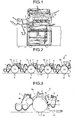
- Fig. 1 is a side view of a tandem-type full-color image forming apparatus, such as a color copying machine, according to a first embodiment of the present invention.
- the image forming apparatus includes an electrophotographic image forming mechanism U.
- Fig. 2 is a side view of the image forming mechanism U.
- the image forming mechanism U includes four toner-image forming units. Each toner-image forming unit forms toner images in a single color each corresponding to yellow, magenta, cyan, or black.
- a toner-image forming unit corresponding to yellow includes a rotatable photosensitive drum 1Y that forms a single color image in yellow
- a toner-image forming unit corresponding to cyan includes a rotatable photosensitive drum 1C that forms a single color image in cyan
- a toner-image forming unit corresponding to magenta includes a rotatable photosensitive drum 1M that forms a single color image in magenta
- a toner-image forming unit corresponding to black includes a rotatable photosensitive drum 1B that forms a single color image in black.
- each toner-image forming unit includes a light exposing unit 3 (see Fig. 1), a toner-image developing unit 4, an intermediate transfer unit 5, a fixing unit 6, and a drum-cleaning unit 7 arranged around the corresponding photosensitive drum 1Y, 1C, 1M, or 1B.
- the fixing unit 6 is arranged on the downstream of the intermediate transfer unit 5.
- toner images in the corresponding single color are formed.
- the photosensitive drums 1Y, 1C, 1M, and 1B are sequentially arranged in a line along the direction of movement of an intermediate transfer belt 10.
- FIG. 3 is an enlarged side view of the toner-image forming unit corresponding to yellow.
- the toner-image forming unit corresponding to magenta or cyan has the same or similar configuration.
- the non-contact charging unit 2 electrically charges the photosensitive drum 1Y (1C or 1M).
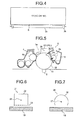
- Fig. 4 is an enlarged perspective view depicting detailed arrangement of the non-contact charging unit 2.
- Fig. 5 is an enlarged perspective view of the toner-image forming unit corresponding to black.
- the corona charging unit 20 functions as a scorotron charging mechanism 21, which is a type of a corona charging mechanism, and electrically charges the photosensitive drum 1B.
- Fig. 6 is an enlarged view depicting detailed arrangement of the scorotron charging mechanism 21 with respect to the photosensitive drum 1B shown in Fig. 5.
- Fig. 7 is an enlarged perspective view depicting detailed arrangement of the corona charging unit 20 that functions as a corotron charging mechanism 25, which is another type of a corona charging mechanism, with respect to the photosensitive drum 1B shown in Fig. 5.
- the photosensitive drums 1Y, 1C, 1M, and 1B which function as latent image carriers, can be made of photoconductive amorphous metals such as amorphous silicon or amorphous selenium, or organic compounds such as azo pigment or phthalocyanine. It is recommended to use the organic compounds as they are eco-friendly and easy to after-treat. To prevent abrasion wear of the surface of such an organic photosensitive drum, a protective layer is laid on its surface.
- a resin having a cross-linked structure is used, or inorganic particulates such as silicon dioxide (SiO 2 , also known as silica), aluminum oxide (also known as alumina), zinc oxide, or titanium oxide (also known as titania) are mixed in the protective layer in the range of 3 wt% to 70 wt%.
- organic photosensitive drums are used as the photosensitive drums 1Y, 1C, 1M, and 1B, and a protective layer of approximately 5 micrometers is laid on the charge-transport layer of each of the photosensitive drums 1Y, 1C, 1M, and 1B.
- Both the charge-transport layer and the protective layer include a binder resin in the form of polycarbonate, 7 wt% of charge transport material, and 10 wt% of silica powder used for enhancing the physical strength of the charge-transport layer and protective layer.
- the photosensitive drums 1Y, 1C, 1M, and 1B are sequentially and equidistantly arranged in a line along the direction of movement (shown by an arrow mark in Fig. 2) of the intermediate transfer belt 10.
- the photosensitive drum 1Y is arranged on the mostupstream, while the photosensitive drum 1B having the highest frequency of usage is arranged on the mostdownstream.
- the photosensitive drums 1C and 1M are arranged in between the photosensitive drums 1Y and 1B.
- the photosensitive drum 1B which is electrically charged by the corona charging unit 20, either on the upstream end or on the downstream end along the direction of movement of the intermediate transfer belt 10.
- the reason for that is as follows.
- the most important factor in an image forming process is the printing speed of a black image. In other words, it is preferable to minimize the time required for a black image to be transferred onto a transfer paper from the photosensitive drum 1B. That can be achieved by arranging the photosensitive drum 1B on the downstream end along the direction of movement of the intermediate transfer belt 10.
- the image forming mechanism U only the photosensitive drum 1B is electrically charged by using the corona charging unit 20.
- the corona charging unit 20 functions as the scorotron charging mechanism 21, as shown in Fig. 5.
- the rest of the photosensitive drums 1Y, 1C, and 1M are electrically charged by using the non-contact charging unit 2.
- the non-contact charging unit 2 includes a charging roller 2a and a power supply unit (not shown).
- the outer surface of the cored bar of the charging roller 2a has either one or both of an elastic layer and a resin layer.
- the power supply unit apples a voltage to the charging roller 2a. Because of the voltage difference between the charging roller 2a and the corresponding photosensitive drum 1Y, discharging occurs in the space S between the charging roller 2a and the photosensitive drum 1Y (1C or 1M). As a result, the surface of the photosensitive drum 1Y (1C or 1M) gets uniformly charged.
- the elastic layer can be made of an electrically conductive rubber having a degree of hardness in the range of 30 to 80 according to JIS-A standard or an electrically conductive sponge material having a degree of hardness in the range of 15 to 60 according to asker-C standard.
- the electrically conductive sponge material can be made of mixing acrylonitrile-butadiene rubber (NBR), chloroprene rubber (CR), ethylene propylene diene monomer (EPDM), or urethane rubber with electrically conductive fillers of carbon or titanium oxide mixed therein.
- the electrically conductive sponge material can also be made of an ion-conductive epichlorohydrin rubber, or a combination of the epichlorohydrin rubber and the other types of rubber described above.
- the charging roller 2a is made of an elastic material having a higher degree of hardness (in the range of 70 to 90 according to JIS-A standard) or a resin material having a superior outer diameter accuracy.
- Various resin materials can be used as the elastic layer if their electrical conductivity is secured.
- resin materials such as acrylic urethane, polyethylene resin, polystyrene, acrylonitrile-butadiene styrene polymer (ABS), polycarbonate, or fluorinated resin.
- a material to control the conducting properties is mixed to the resin material and the volume resistance of the elastic layer is adjusted to be in the range of 6 log ⁇ m to 10 logS2cm.
- a gap maintaining mechanism 2b is arranged at both ends of the charging roller 2a in a portion where an image is not formed on the photosensitive drum 1Y (1C or 1M) on which no image is formed.
- the gap maintaining mechanism 2b can be a roller or a tape with uniform thickness that can maintain the rolling axis of the charging roller 2a at a constant distance from the central axis of the photosensitive drum 1Y (1C or 1M). It is recommended to maintain the gap S in the range of 10 micrometers to 500 micrometers. A smaller gap S enables to reduce the cost related to the voltage applied to the charging roller 2a. However, if the gap S is too small, then it becomes necessary to increase the machine accuracy to maintain the gap S. As a result, the assembly of the toner-image forming unit becomes complicated. Moreover, the charging roller 2a may gather dirt because of the toner coming into the gap S or foreign material present on the photosensitive drum 1Y (1C or 1M). Hence, it is preferable to maintain the gap S in the range of 30 micrometers to 60 micrometers.
- a smooth surface with good releasability prevents the charging toner from catching dirt.
- a surface can be made of a fluorinated material or a silicon material.
- corona discharging Another way to electrically charge a photoconductive drum by a non-contact charging mechanism is to use corona discharging.
- a thin wire of diameter in the range of 50 micrometers to 100 micrometers is arranged on a metal electrode.
- corona discharging When a voltage is applied to the metal electrode, discharging phenomenon in violet color occurs in the proximity of the wire until the wire undergoes sparking discharge. This is called corona discharging.
- the corona discharging has a negative discharging and a positive discharging, which depends on the polarity of the applied voltage.
- negative discharging there is high possibility of uneven discharging, which badly affects uniform charging of the photosensitive drum.
- Fig. 5 is an enlarged side view of the toner-image forming unit corresponding to black.
- the corona charging unit 20 functions as a scorotron charging mechanism 21 to electrically charge the photosensitive drum 1B.
- Fig. 6 is an enlarged side view depicting detailed arrangement of the scorotron charging mechanism 21 with respect to the photosensitive drum 1B shown in Fig. 5. As shown in Fig.
- the scorotron charging mechanism 21 includes a rectangular shield 22 that has an opening towards the photosensitive drum 1B, a striated discharging electrode 23 lined inside the shield 22, and a grid electrode 24 that is arranged between the discharging electrode 23 and the photosensitive drum 1B.
- the grid electrode 24 is arranged between the opening of the shield 22 and the photosensitive drum 1B. An intended voltage is applied to the grid electrode 24 such that the photosensitive drum 1B is uniformly charged.
- Fig. 7 is an enlarged side view depicting detailed arrangement of the corona charging unit 20, which functions as a corotron charging mechanism 25, with respect to the photosensitive drum 1B shown in Fig. 5.
- the corotron charging mechanism 25 can be used instead of the scorotron charging mechanism 21.
- the corotron charging mechanism 25 includes a cylindrical shield 26 that has an opening towards the photosensitive drum 1B and a striated discharging electrode 27 lined inside the shield 26.
- the corotron charging mechanism 25 is arranged directly on the photosensitive drum 1B. A high voltage of intended polarity is applied to the discharging electrode 27 such that the photosensitive drum 1B is uniformly charged.
- a scorotron charging mechanism is usually used instead of a corotron charging mechanism to charge the negatively charged organic photosensitive drums.
- a corona charging mechanism is implemented to charge a photosensitive drum, poison gases such as ozone are produced, which are hazardous to the environment.
- an air-blowing mechanism to exhaust the poison gas. That results in upsizing the image forming apparatus as well as increasing the production cost.
- tandem-type image forming apparatuses In recent years, most image forming apparatuses are configured to adopt a tandem method for image forming to enhance the efficiency in outputting color images.
- tandem-type image forming apparatuses a plurality of image forming units are sequentially arranged and form a full-color image on a paper that is conveyed to each image forming unit only once.
- tandem-type image forming apparatuses in which a charging mechanism is implemented by using charging rollers are becoming popular because of their compactness.
- a corona charging mechanism is usually implemented in large image forming apparatuses that require higher processing speed.
- the scorotron charging mechanism 21 which is a type of non-contact corona charging mechanism, is implemented to charge only the photosensitive drum 1B having the highest frequency of usage.
- the non-contact charging unit 2 which functions as a non-contact charging mechanism by using the charging roller 2a, is implemented to charge the rest of the photosensitive drums 1Y, 1C, and 1M.
- the image forming apparatus is downsized.
- the photosensitive drums 1Y, 1C, and 1M do not come into contact with the non-contact charging unit 2, their deterioration due to the abrasion wear is prevented and durability is improved.
- the image forming mechanism U can be configured such that the corona charging unit 20 (scorotron charging mechanism 21) is used to charge at least the photosensitive drum 1B, while the non-contact charging unit 2 is used to charge at least one of the photosensitive drums 1Y, 1C, and 1M.
- the corona charging unit 20 corotron charging mechanism 21
- the non-contact charging unit 2 is used to charge at least one of the photosensitive drums 1Y, 1C, and 1M.
- the non-contact charging unit 2 charges the photosensitive drums 1Y, 1C, and 1M by using alternate current (AC) superimposition charging instead of direct current (DC) charging.
- AC alternate current
- DC direct current
- the image quality does not deteriorate and the durability of the non-contact charging unit 2 improves.
- AC-superimposition charging when the photosensitive drums 1Y, 1C, and 1M rotate under the corresponding non-contact charging unit 2, discharging occurs for several times thereby uniformly charging the photosensitive drums 1Y, 1C, and 1M.
- Another merit is that a small amount of dirt on the surface of the photosensitive drums 1Y, 1C, and 1M does not have any effect on the image forming.
- the surface of the photosensitive drums 1Y, 1C, and 1M is subjected to electrostatic damage. Even in case of the scorotron charging mechanism 21, the surface of the photosensitive drum 1B gets damaged due to the corona discharging. However, the damage to the surface of the photosensitive drum 1B is less than that in case of the photosensitive drums 1Y, 1C, and 1M because the amount of discharging in the scorotron charging mechanism 21 is less than that in the non-contact charging unit 2.
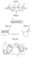
- a surface protectant 1a on the surface of the photosensitive drums 1Y, 1C, 1M, and 1B (see Fig. 10).
- the amount of the surface protectant 1a can be adjusted corresponding to each photosensitive drum 1Y, 1C, 1M, and 1B such that there is no wastage of the surface protectant 1a.
- the amount of the surface protectant 1a required for the photosensitive drum 1B is much less than that required for the other photosensitive drums 1Y, 1C, and 1M.
- a configuration is allowable in which the surface protectant 1a is not applied to the photosensitive drum 1B. Instead, a polishing blade 7c, as shown in Fig. 11, is arranged to scrape out foreign materials that get attached to the surface of the photosensitive drum 1B. As a result, uneven charging of the photosensitive drum 1B is prevented without any wastage of the surface protectant 1a.
- the light exposing unit 3 receives data from a scanning device or image signals from an outside component such as a personal computer (not shown). The light exposing unit 3 then performs transformation of the image signals, scans the image signals with a laser light 3a by using a polygon motor, and based on the image signals that pass the polygon mirror forms latent images on the photosensitive drums 1Y, 1C, 1M, and 1B.
- the toner-image developing unit 4 includes a hollow and cylindrical developer carrier 4a (see Fig. 3) that carries the developer and supplies it to the photosensitive drum 1Y (1C, 1M, and 1B), a developer-amount controlling unit that controls the amount of developer carried by the developer carrier 4a, and a toner feeding chamber.
- the developer carrier 4a is pivotably supported around an inside shaft to which a magnet-roll is also fixed.
- the developer carrier 4a is arranged to keep a small distance from the photosensitive drum 1Y (1C, 1M, or 1B).
- a predetermined amount of developer is magnetically adsorbed to the outer surface of the developer carrier 4a and then supplied to the photosensitive drum 1Y (1C, 1M, or 1B).
- the developer carrier 4a is made of an electrically conductive and nonmagnetic material.
- a power supply unit applies a developing bias to the developer carrier 4a.
- the power supply unit applies voltage in between the developer carrier 4a and the photosensitive drum 1Y (1C, 1M, or 1B) such that an electric field is generated in the developing area.
- the intermediate transfer unit 5 is arranged corresponding to each photosensitive drum 1Y, 1C, 1M, and 1B on the inner side of the intermediate transfer belt 10, as shown in Fig. 2.
- the fixing unit 6 (see Fig. 1) includes a fixing roller 6a and a pressurized roller 6b.
- the fixing roller 6a performs heat fixing by using a heater made of, e.g., halogen lamp.
- the pressurized roller 6b is crimped by the fixing roller 6a.
- the surface of the cored bar of the fixing roller 6a is covered by an elastic layer of, e.g., silicon rubber.
- the thickness of the elastic layer is kept in the range of 100 micrometers to 500 micrometers although it is recommended to keep a thickness of 400 micrometers.
- the fixing roller 6a is covered by a resin layer with good releasability such as a fluorinated resin layer.
- the resin layer is made of a tetrafluoroethylene-perfluoroalkyl vinyl ether (PFA) tube and it is recommended to keep its thickness in the range of 10 micrometers to 50 micrometers to minimize the mechanical deterioration.
- a temperature detecting unit is arranged at the outer surface of the fixing roller 6a. The heater is regulated to maintain a substantially uniform surface temperature in the range of 160 °C to 200 °C.
- the surface of the cored bar of the pressurized roller 6b is covered by an offset preventing layer made of tetrafluoroethylene-perfluoroalkyl vinyl ether (PFA) or polytetrafluoroethylene (PTFE). Similar to the fixing roller 6a, an elastic layer of silicon rubber can also be used to cover the cored bar of the pressurized roller 6b.
- a belt fixing unit can be used in which rollers are belt-shaped.
- an induction heat fixing method can be applied in which heat is generated by the eddy current produced by an outside magnetic force.
- the drum-cleaning unit 7 (see Figs. 3 and 5) includes the first cleaning blade 7a, a second cleaning blade 7b, a waste-toner scooping blade (not shown) that scoops the waste toner after cleaning, a waste-toner carrying coil (not shown), and a waste-toner box (not shown) to which the waste toner is carried by the waste-toner carrying coil.
- the first cleaning blade 7a and the second cleaning blade 7b are sequentially arranged along the direction of movement of the photosensitive drum 1Y (1C or 1M) or 1B such that the first cleaning blade 7a cleans the photosensitive drum 1Y (1C or 1M) or 1B before the second cleaning blade 7b cleans the same.
- the first cleaning blade 7a can be made of metal, resin, or rubber.
- various types of materials such as fluorinated resin, silicon rubber, butyl rubber, butadiene rubber, isoprene rubber, and polyurethane rubber are widely used for making the first cleaning blade 7a among which it is particularly recommended to use polyurethane rubber.
- the first cleaning blade 7a mainly scrapes out the residual toner on the photosensitive drum 1Y (1C or 1M) or 1B after the image transfer is complete.
- the second cleaning blade 7b scrapes out the foreign material from the filming formed due to toner additives on the,photosensitive drum 1Y (1C or 1M) or 1B.
- the second cleaning blade 7b can be made from the material same as that of the first cleaning blade 7a. However, to scrape out the foreign material more effectively, it is recommended to use an abrasive blade that is made of an elastic material with granules of an abrasive agent.
- the drum-cleaning unit 7 also includes a lubricant coating mechanism 8 that is arranged between the first cleaning blade 7a and the second cleaning blade 7b.
- the lubricant coating mechanism 8 includes a lubricant 9 in solid form, a lubricant scraping member 8a that scrapes the lubricant 9, and a brush roller 8b that coats' the surface of the photosensitive drum 1Y (1C or 1M) or 1B with the powder of the lubricant 9 scraped by the lubricant scraping member 8a.
- a lubricant can be in solid form or liquid form.
- the lubricant 9 is used in solid form considering the coating efficiency, convenience of portability, and prevention of leakage at the time of maintenance.
- the drum-cleaning unit can be configured to include one or more cleaning blades.
- the lubricant coating mechanism 8 also functions as a residual-toner collecting mechanism. After the toner image is primary-transferred, the residual toner on the photosensitive drum 1Y (1C or 1M) or 1B is collected at the corresponding lubricant coating mechanism 8. The surface of the photosensitive drum 1Y (1C or 1M) or 1B is then coated with the powder of the lubricant 9. Finally, the first cleaning blade 7a scrapes out the still residual toner or filming of the toner additives from the surface of the photosensitive drum 1Y (1C or 1M) or 1B.
- the fur of the brush roller 8b is made by adding to resin material such as nylon or acrylic a resistant material such as carbon black, and adjusting the volume resistance of that mixture in the range of 3 log ⁇ cm to 61 log ⁇ cm.
- the brush roller 8b is kept connected to the lubricant 9 via the lubricant scraping member 8a by using the urging force of a spring.
- the lubricant 9 can be made of a metallic soap of lead oleate, zinc oleate, copper oleate, zinc stearate, cobalt stearate, iron stearate, copper stearate, zinc palmitate, copper palmitate, or lead linolenate.
- These metallic soaps are saturated resin compounds having lamellar atomic structure and excellent lubricating effect.
- zinc stearate is recommended because it has excellent and proven durability as well as lubricating property.
- the lubricant 9 can be used in the form of a lubricant compact by rubbing the powder of zinc stearate or calcium stearate on a solid compact.
- the minute particles of the lubricant 9 scraped by the lubricant scraping member 8a are deposited on the surface of the photosensitive drum 1Y (1C or 1M) or 1B.
- the minute particles of the lubricant 9 are milled to form a thin film over the photosensitive drum 1Y (1C or 1M) or 1B.
- the friction coefficient of the surface of the photosensitive drum 1Y (1C or 1M) or 1B is reduced.
- the photosensitive drums 1Y, 1C, 1M, and 1B can be coated directly with the powder of zinc stearate or calcium stearate by using a powder coating mechanism.
- Fig. 8 is a side view of the arrangement of the photosensitive drums 1Y, 1C, 1M, and 1B and the intermediate transfer belt 10.
- Fig. 9 is a cross-section of the intermediate transfer belt 10.
- the intermediate transfer belt 10 includes a base layer 11, an elastic layer 12 that lies on the base layer 11, and a smooth coat layer 13 that covers the elastic layer 12.
- the base layer 11 is a made of a not-very-elastic fluorinated resin or an elastic rubber material mixed with a not-very-elastic canvas.
- the elastic layer 12 is made of, e.g., acrylonitrile-butadiene rubber.
- the coat layer 13 is a layer of, e.g., fluorinated resin that is coated on the elastic layer 12.
- the intermediate transfer belt 10 is rotatable in the clockwise direction and is stretched around a first supporting roller 14, a second supporting roller 15, and a third supporting roller 16.
- An intermediate-transfer-belt cleaning unit 17 is arranged between the second supporting roller 15 and the third supporting roller 16.
- the intermediate-transfer-belt cleaning unit 17 removes the residual toner on the intermediate transfer belt 10 after the process of image transfer is complete.
- the photosensitive drums 1Y, 1C, 1M, and 1B are sequentially arranged in a line between the third supporting roller 16 and the first supporting roller 14 along the direction of movement of the intermediate transfer belt 10.
- a direct transfer mechanism can be used in which a conveyer belt conveys a transfer paper such that a toner image on each of the photosensitive drums 1Y, 1C, 1M, and 1B is directly transferred onto the transfer paper to form a full-color image.
- Fig. 12 is a side view of a process cartridge 30 that can be detachably attached to the image forming apparatus.
- the process cartridge 30 can be configured by unitizing some of the components of the toner-image forming unit.
- four process cartridges 30 are configured.
- Each process cartridge 30 includes one of the photosensitive drums 1Y, 1C, 1M, and 1B, the corresponding charging unit, viz., the non-contact charging unit 2 or the corona charging unit 20, and any one or both of the corresponding toner-image developing unit 4 and the drum-cleaning unit 7. Because the process cartridges 30 are detachable from the image forming apparatus, replacing them in case of malfunctioning is not difficult.
- the first experiment was performed to verify the difference in the amount of abrasion wear of the first cleaning blade 7a under two conditions. Under the first condition, the lubricant 9 was applied on the surface of the corresponding photosensitive drum 1Y, 1C, or 1M. Under the second condition, the lubricant 9 was not applied.
- the image forming apparatus was set to print 150,000 papers of A4 size under both conditions and the corresponding maximum depth of abrasion wear of the first cleaning blade 7a was measured.
- the lubricant 9 was deposited on a spindle and pressure was applied to the spindle to adjust the amount of the lubricant 9 to be applied.
- the depth of abrasion wear of the first cleaning blade 7a was measured when the distance traveled by the photosensitive drum 1Y, 1C, or 1M under each condition reached 40 kilometers.
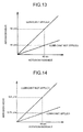
- Fig. 13 is a graph depicting the result of the first experiment.
- the depth of abrasion wear of the first cleaning blade 7a was approximately 30 micrometers.
- the depth of abrasion wear of the first cleaning blade 7a was approximately 14 micrometers.
- the depth of abrasion wear of the first cleaning blade 7a when the lubricant 9 was applied on the surface of the photosensitive drum 1Y, 1C, or 1M was more than double when the lubricant 9 was not applied.
- the second experiment was performed to verify the difference in the amount of abrasion wear of the photosensitive drums 1Y, 1C, and 1M, which were charged by the non-contact charging unit 2, under two conditions. Under the first condition, the lubricant 9 was applied on the surface of the photosensitive drums 1Y, 1C, and 1M. Under the second condition, the lubricant 9 was not applied.
- the image forming apparatus was set to print 150,000 papers of A4 size under both conditions and the corresponding maximum depth of abrasion wear of the photosensitive drums 1Y, 1C, and 1M was measured. The depth of abrasion wear was measured when the distance traveled by the photosensitive drums 1Y, 1C, and 1M under each condition reached 40 kilometers. Fig.
- FIG. 14 is a graph depicting the result of the second experiment.
- the depth of abrasion wear of the photosensitive drums 1Y, 1C, and 1M was approximately 0.75 micrometers.
- the depth of abrasion wear of the photosensitive drums 1Y, 1C, and 1M was approximately 5.5 micrometers.
- the depth of abrasion wear of the photosensitive drums 1Y, 1C, and 1M with the lubricant 9 was more than seven times when the lubricant 9 was not applied.
- the third experiment was performed to verify the effect of the protective layer laid on the photosensitive drum 1B, which was charged by the corona charging unit 20.
- the lubricant 9 was not applied on the surface of the photosensitive drum 1B.
- the experiment was performed under two conditions. Under the first condition, the protective layer was laid on the surface of the photosensitive drum 1B. Under the second condition, the surface of the photosensitive drum 1B was without the protective layer.
- the image forming apparatus was set to print 150,000 papers of A4 size under both conditions and the corresponding maximum depth of abrasion wear of photosensitive drum 1B was measured when the distance traveled by the photosensitive drum 1B under each condition reached 40 kilometers.
- Fig. 15 is a graph depicting the result of the third experiment.
- the depth of abrasion wear of the photosensitive drum 1B was approximately 0.6 micrometers.
- the depth of abrasion wear of the photosensitive drum 1B was approximately 2.5 micrometers. Hence, it is recommended to lay the protective layer on the surface of the photosensitive drum 1B.
- the fourth experiment was performed to verify the effect on the first cleaning blade 7a when the lubricant 9 was applied on the surface of the photosensitive drum 1B, which was charged by the corona charging unit 20.
- the image forming apparatus was set to print 150,000 papers of A4 size under three conditions and the corresponding maximum depth of abrasion wear of the first cleaning blade 7a was measured. Under the first condition, the lubricant 9 was not applied on the surface of the photosensitive drum 1B. Under the second condition, only one spindle was used for applying the lubricant 9. Under the second condition, a small amount of lubricant 9 was applied on the surface of the photosensitive drum 1B by using one spindle.
- a large amount of lubricant 9 was applied on the surface of the photosensitive drum 1B by using two spindles.
- the depth of abrasion wear of the first cleaning blade 7a was measured when the distance traveled by the photosensitive drum 1B reached 40 kilometers.
- Fig. 16 is a graph depicting the result of the fourth experiment.
- the depth of abrasion wear of the first cleaning blade 7a was approximately 14 micrometers.
- the depth of abrasion wear of the first cleaning blade 7a was approximately 30 micrometers.
- the depth of abrasion wear of the first cleaning blade 7a was approximately 44 micrometers.
- the depth of abrasion wear of the first cleaning blade 7a was directly proportional to the amount of the lubricant 9 applied on the surface of the photosensitive drum 1B.
- an image forming apparatus includes a plurality of toner-image forming units.
- Each toner-image forming unit includes a rotatable photosensitive drum and a charging unit that electrically charges the corresponding photosensitive drum.
- At least one of the charging units functions as a corona charging mechanism and at least another one of the charging units functions as a non-contact charging mechanism.
- the corona charging mechanism is implemented to charge only one photosensitive drum that forms electrostatic latent images in black and has a high frequency of usage, it is possible to avoid frequent replacement of the toner-image forming unit that includes the photosensitive drum for forming black images.
- the image forming apparatus is downsized to a compact size. Moreover, because the photosensitive drums do not come into contact with the corresponding charging rollers, damage due to the abrasion wear is prevented and durability is improved. Thus, by implementing two different charging mechanisms, viz., the corona charging mechanism and the non-contact charging mechanism depending on the corresponding photosensitive drums, enhanced charging performance can be achieved.
- the surface of the photosensitive drums that are charged by the non-contact charging mechanism is coated with a lubricant in solid form, which also functions as a surface protectant.
- the surface of the photosensitive drum that is charged by the corona charging mechanism is not coated with the lubricant. As a result, it is possible to reduce the amount of abrasion wear of the photosensitive drum that forms black images and has a high frequency of usage, and a cleaning blade corresponding to that photosensitive drum.
- a protective layer including an inorganic filler is laid on the surface of a11 the photosensitive drums. That helps in reducing the amount of abrasion wear of the photosensitive drums due to the friction with the blades.
- the non-contact charging mechanism is implemented to charge the photosensitive drums that form images in color other than black by using alternate current (AC) superimposition charging. That helps in performing stable and uniform charging of the photosensitive drums.
- AC alternate current
- each photosensitive drum and a developer corresponding to that photosensitive drum are unitized to form a process cartridge that is detachable from the image forming apparatus. As a result, maintenance of the image forming apparatus becomes simple thereby reducing the users work.
- a polishing mechanism is arranged to remove foreign materials attached on the surface of the photosensitive drums. Thus, the toner additives are removed and deterioration of the image quality is prevented.
Landscapes
- Physics & Mathematics (AREA)
- General Physics & Mathematics (AREA)
- Engineering & Computer Science (AREA)
- Plasma & Fusion (AREA)
- Electrostatic Charge, Transfer And Separation In Electrography (AREA)
- Cleaning In Electrography (AREA)
- Color Electrophotography (AREA)
- Electrophotography Configuration And Component (AREA)
Applications Claiming Priority (1)
| Application Number | Priority Date | Filing Date | Title |
|---|---|---|---|
| JP2006252606A JP4963208B2 (ja) | 2006-09-19 | 2006-09-19 | 画像形成ユニット、プロセスカートリッジ、及び画像形成装置 |
Publications (3)
| Publication Number | Publication Date |
|---|---|
| EP1903406A2 true EP1903406A2 (de) | 2008-03-26 |
| EP1903406A3 EP1903406A3 (de) | 2008-04-09 |
| EP1903406B1 EP1903406B1 (de) | 2016-11-02 |
Family
ID=38686646
Family Applications (1)
| Application Number | Title | Priority Date | Filing Date |
|---|---|---|---|
| EP07115683.0A Ceased EP1903406B1 (de) | 2006-09-19 | 2007-09-05 | Bilderzeugungseinheit, Prozesskartusche und Bilderzeugungsvorrichtung |
Country Status (3)
| Country | Link |
|---|---|
| US (1) | US7715761B2 (de) |
| EP (1) | EP1903406B1 (de) |
| JP (1) | JP4963208B2 (de) |
Cited By (2)
| Publication number | Priority date | Publication date | Assignee | Title |
|---|---|---|---|---|
| EP1990686A1 (de) | 2007-05-11 | 2008-11-12 | Ricoh Company, Ltd. | Übertragungseinheit und Bilderzeugungsvorrichtung damit |
| EP2012197A2 (de) | 2007-07-05 | 2009-01-07 | Ricoh Company, Ltd. | Bilderzeugungsvorrichtung und Prozesskartusche |
Families Citing this family (12)
| Publication number | Priority date | Publication date | Assignee | Title |
|---|---|---|---|---|
| JP4419451B2 (ja) * | 2003-06-20 | 2010-02-24 | コニカミノルタビジネステクノロジーズ株式会社 | タンデム画像形成システム |
| JP5005991B2 (ja) * | 2006-09-15 | 2012-08-22 | 株式会社リコー | 画像形成装置 |
| JP4572356B2 (ja) * | 2008-07-25 | 2010-11-04 | セイコーエプソン株式会社 | 画像形成装置及び画像形成方法 |
| JP4653204B2 (ja) * | 2008-09-16 | 2011-03-16 | 住友ゴム工業株式会社 | 導電性ロール |
| JP5472577B2 (ja) * | 2009-03-11 | 2014-04-16 | 株式会社リコー | 画像形成装置 |
| JP5338480B2 (ja) * | 2009-05-25 | 2013-11-13 | 株式会社リコー | 画像形成装置 |
| JP5625526B2 (ja) | 2010-06-18 | 2014-11-19 | 株式会社リコー | 画像形成装置及びプロセスカートリッジ |
| JP5605697B2 (ja) * | 2010-09-15 | 2014-10-15 | 株式会社リコー | 画像形成装置 |
| JP2013064899A (ja) * | 2011-09-19 | 2013-04-11 | Ricoh Co Ltd | 画像形成装置 |
| JP5370534B2 (ja) * | 2012-05-21 | 2013-12-18 | 株式会社リコー | 潤滑剤塗布装置、プロセスカートリッジおよび画像形成装置 |
| US9317006B2 (en) * | 2013-11-22 | 2016-04-19 | Flo-Tech, Llc | Laser print cartridge with removable paper cleaning assembly |
| DE102015108776B3 (de) * | 2015-06-03 | 2016-06-02 | Océ Printing Systems GmbH & Co. KG | Verfahren und Vorrichtung zur Verbesserung des Tonertransfers in einem Digitaldrucker durch Aufbringen einer leitfähigen Flüssigkeit |
Citations (1)
| Publication number | Priority date | Publication date | Assignee | Title |
|---|---|---|---|---|
| JPH05307279A (ja) | 1991-03-25 | 1993-11-19 | Katsuragawa Electric Co Ltd | 帯電方法 |
Family Cites Families (18)
| Publication number | Priority date | Publication date | Assignee | Title |
|---|---|---|---|---|
| JPS614082A (ja) * | 1984-06-18 | 1986-01-09 | Canon Inc | コロナ放電装置 |
| JP2829629B2 (ja) * | 1988-07-01 | 1998-11-25 | キヤノン株式会社 | アモルファスシリコン系感光体を用いた電子写真法による画像形成方法及び電子写真装置 |
| JPH02141761A (ja) * | 1988-11-22 | 1990-05-31 | Canon Inc | 電子写真装置 |
| JP3517085B2 (ja) * | 1997-05-28 | 2004-04-05 | 京セラ株式会社 | 画像形成装置 |
| JPH1191205A (ja) * | 1997-09-22 | 1999-04-06 | Toshiba Corp | 画像形成装置 |
| JP3795709B2 (ja) * | 1999-07-19 | 2006-07-12 | 株式会社リコー | 画像形成装置 |
| JP3587094B2 (ja) * | 1999-08-06 | 2004-11-10 | 富士ゼロックス株式会社 | カラー画像形成装置 |
| JP4375699B2 (ja) * | 2000-09-14 | 2009-12-02 | 株式会社リコー | タンデム作像装置およびそれを備える画像形成装置、ならびに作像手段の配置方法 |
| US6611672B2 (en) * | 2000-09-26 | 2003-08-26 | Ricoh Company, Ltd. | Image forming apparatus, monocolor image forming apparatus, toner recycling apparatus and intermediate transfer member |
| JP4194776B2 (ja) * | 2000-11-10 | 2008-12-10 | 株式会社リコー | 電子写真感光体、その製造方法、電子写真方法及び電子写真装置 |
| JP2002156806A (ja) | 2000-11-22 | 2002-05-31 | Fuji Xerox Co Ltd | 画像形成装置 |
| JP2002244487A (ja) * | 2001-02-21 | 2002-08-30 | Canon Inc | 画像形成装置 |
| JP2002341618A (ja) * | 2001-03-16 | 2002-11-29 | Ricoh Co Ltd | フルカラー電子写真装置 |
| JP3850329B2 (ja) * | 2002-04-17 | 2006-11-29 | 京セラ株式会社 | 画像形成装置 |
| JP2004061855A (ja) * | 2002-07-29 | 2004-02-26 | Konica Minolta Holdings Inc | 画像形成装置 |
| JP4376053B2 (ja) * | 2003-02-18 | 2009-12-02 | 株式会社リコー | 画像形成装置 |
| JP4516771B2 (ja) * | 2004-03-18 | 2010-08-04 | 株式会社リコー | 画像形成装置 |
| JP4897250B2 (ja) * | 2005-06-30 | 2012-03-14 | 株式会社リコー | 画像形成方法および画像形成装置 |
-
2006
- 2006-09-19 JP JP2006252606A patent/JP4963208B2/ja not_active Expired - Fee Related
-
2007
- 2007-09-05 EP EP07115683.0A patent/EP1903406B1/de not_active Ceased
- 2007-09-10 US US11/852,572 patent/US7715761B2/en not_active Expired - Fee Related
Patent Citations (1)
| Publication number | Priority date | Publication date | Assignee | Title |
|---|---|---|---|---|
| JPH05307279A (ja) | 1991-03-25 | 1993-11-19 | Katsuragawa Electric Co Ltd | 帯電方法 |
Cited By (5)
| Publication number | Priority date | Publication date | Assignee | Title |
|---|---|---|---|---|
| EP1990686A1 (de) | 2007-05-11 | 2008-11-12 | Ricoh Company, Ltd. | Übertragungseinheit und Bilderzeugungsvorrichtung damit |
| US7813662B2 (en) | 2007-05-11 | 2010-10-12 | Ricoh Company Limited | Transfer unit and image forming apparatus using the unit |
| EP2012197A2 (de) | 2007-07-05 | 2009-01-07 | Ricoh Company, Ltd. | Bilderzeugungsvorrichtung und Prozesskartusche |
| EP2012197A3 (de) * | 2007-07-05 | 2009-03-11 | Ricoh Company, Ltd. | Bilderzeugungsvorrichtung und Prozesskartusche |
| US8204422B2 (en) | 2007-07-05 | 2012-06-19 | Ricoh Company, Limited | Image forming apparatus and process cartridge having a charging unit |
Also Published As
| Publication number | Publication date |
|---|---|
| US20080260438A1 (en) | 2008-10-23 |
| JP4963208B2 (ja) | 2012-06-27 |
| JP2008076498A (ja) | 2008-04-03 |
| EP1903406B1 (de) | 2016-11-02 |
| US7715761B2 (en) | 2010-05-11 |
| EP1903406A3 (de) | 2008-04-09 |
Similar Documents
| Publication | Publication Date | Title |
|---|---|---|
| US7715761B2 (en) | Image forming unit, process cartridge, and image forming apparatus | |
| US7383013B2 (en) | Image forming apparatus using a contact or a proximity type of charging system including a protection substance on a moveable body to be charged | |
| CN101598918B (zh) | 成像装置 | |
| KR100862932B1 (ko) | 클리닝 장치, 프로세스 카트리지 및 화상 형성 장치 | |
| JP5239268B2 (ja) | 画像形成装置 | |
| EP1542087B1 (de) | Verfahren zur Herstellung einer Photoleitereinheit zum Aufbringen eines gleichmässigen Ladungszustandes auf eine photoleitende Oberfläche | |
| KR100840595B1 (ko) | 화상 형성 장치 | |
| US7113726B2 (en) | Charging device, image forming process cartridge, and image forming apparatus including the charging device | |
| JP4208513B2 (ja) | 画像形成装置 | |
| US8849160B2 (en) | Bias charge roller having a continuous raised pattern on the outer surface | |
| JP4760313B2 (ja) | 画像形成装置 | |
| JP5724440B2 (ja) | 画像形成装置 | |
| JP2005115311A (ja) | クリーニング装置、画像形成装置およびプロセスカートリッジ | |
| US20050141923A1 (en) | Image forming apparatus | |
| JP2010164820A (ja) | クリーニング装置、像担持体ユニット及び画像形成装置 | |
| JP2005092146A (ja) | 画像形成装置、帯電部材、帯電装置、クリーニング手段及びプロセスカートリッジ | |
| JP7472683B2 (ja) | 画像形成方法 | |
| JP5322967B2 (ja) | 現像装置及び画像形成装置 | |
| JP2001042751A (ja) | 画像形成装置及びプロセスカートリッジ | |
| JP7606674B2 (ja) | 画像形成装置 | |
| JP5327570B2 (ja) | 画像形成装置 | |
| JP2007193031A (ja) | 画像形成装置 | |
| JP2005024672A (ja) | 導電性部材およびそれを用いた画像形成装置およびプロセスカートリッジ | |
| JP2008008927A (ja) | 画像形成装置 | |
| JP2007199326A (ja) | 画像形成装置 |
Legal Events
| Date | Code | Title | Description |
|---|---|---|---|
| PUAI | Public reference made under article 153(3) epc to a published international application that has entered the european phase |
Free format text: ORIGINAL CODE: 0009012 |
|
| PUAL | Search report despatched |
Free format text: ORIGINAL CODE: 0009013 |
|
| AK | Designated contracting states |
Kind code of ref document: A2 Designated state(s): AT BE BG CH CY CZ DE DK EE ES FI FR GB GR HU IE IS IT LI LT LU LV MC MT NL PL PT RO SE SI SK TR |
|
| AX | Request for extension of the european patent |
Extension state: AL BA HR MK YU |
|
| AK | Designated contracting states |
Kind code of ref document: A3 Designated state(s): AT BE BG CH CY CZ DE DK EE ES FI FR GB GR HU IE IS IT LI LT LU LV MC MT NL PL PT RO SE SI SK TR |
|
| AX | Request for extension of the european patent |
Extension state: AL BA HR MK RS |
|
| 17P | Request for examination filed |
Effective date: 20080829 |
|
| AKX | Designation fees paid |
Designated state(s): DE FR GB |
|
| 17Q | First examination report despatched |
Effective date: 20131015 |
|
| GRAP | Despatch of communication of intention to grant a patent |
Free format text: ORIGINAL CODE: EPIDOSNIGR1 |
|
| INTG | Intention to grant announced |
Effective date: 20160506 |
|
| RIN1 | Information on inventor provided before grant (corrected) |
Inventor name: UDA, JUNROH Inventor name: IWAI, SADAYUKI |
|
| GRAS | Grant fee paid |
Free format text: ORIGINAL CODE: EPIDOSNIGR3 |
|
| GRAA | (expected) grant |
Free format text: ORIGINAL CODE: 0009210 |
|
| AK | Designated contracting states |
Kind code of ref document: B1 Designated state(s): DE FR GB |
|
| REG | Reference to a national code |
Ref country code: GB Ref legal event code: FG4D |
|
| REG | Reference to a national code |
Ref country code: DE Ref legal event code: R096 Ref document number: 602007048536 Country of ref document: DE |
|
| REG | Reference to a national code |
Ref country code: DE Ref legal event code: R097 Ref document number: 602007048536 Country of ref document: DE |
|
| PLBE | No opposition filed within time limit |
Free format text: ORIGINAL CODE: 0009261 |
|
| STAA | Information on the status of an ep patent application or granted ep patent |
Free format text: STATUS: NO OPPOSITION FILED WITHIN TIME LIMIT |
|
| REG | Reference to a national code |
Ref country code: FR Ref legal event code: PLFP Year of fee payment: 11 |
|
| 26N | No opposition filed |
Effective date: 20170803 |
|
| REG | Reference to a national code |
Ref country code: FR Ref legal event code: PLFP Year of fee payment: 12 |
|
| PGFP | Annual fee paid to national office [announced via postgrant information from national office to epo] |
Ref country code: DE Payment date: 20180920 Year of fee payment: 12 Ref country code: FR Payment date: 20180925 Year of fee payment: 12 |
|
| PGFP | Annual fee paid to national office [announced via postgrant information from national office to epo] |
Ref country code: GB Payment date: 20180919 Year of fee payment: 12 |
|
| REG | Reference to a national code |
Ref country code: DE Ref legal event code: R119 Ref document number: 602007048536 Country of ref document: DE |
|
| PG25 | Lapsed in a contracting state [announced via postgrant information from national office to epo] |
Ref country code: DE Free format text: LAPSE BECAUSE OF NON-PAYMENT OF DUE FEES Effective date: 20200401 |
|
| GBPC | Gb: european patent ceased through non-payment of renewal fee |
Effective date: 20190905 |
|
| PG25 | Lapsed in a contracting state [announced via postgrant information from national office to epo] |
Ref country code: GB Free format text: LAPSE BECAUSE OF NON-PAYMENT OF DUE FEES Effective date: 20190905 Ref country code: FR Free format text: LAPSE BECAUSE OF NON-PAYMENT OF DUE FEES Effective date: 20190930 |