EP1991005A2 - Appareil, procédé et programme pour traitement de signal vidéo pour le filtrage temporel d'un signal vidéo avant le traitement d'image du signal vidéo - Google Patents
Appareil, procédé et programme pour traitement de signal vidéo pour le filtrage temporel d'un signal vidéo avant le traitement d'image du signal vidéo Download PDFInfo
- Publication number
- EP1991005A2 EP1991005A2 EP08251390A EP08251390A EP1991005A2 EP 1991005 A2 EP1991005 A2 EP 1991005A2 EP 08251390 A EP08251390 A EP 08251390A EP 08251390 A EP08251390 A EP 08251390A EP 1991005 A2 EP1991005 A2 EP 1991005A2
- Authority
- EP
- European Patent Office
- Prior art keywords
- video signal
- temporal feature
- input video
- processing
- detecting
- Prior art date
- Legal status (The legal status is an assumption and is not a legal conclusion. Google has not performed a legal analysis and makes no representation as to the accuracy of the status listed.)
- Withdrawn
Links
Images





Classifications
-
- H—ELECTRICITY
- H04—ELECTRIC COMMUNICATION TECHNIQUE
- H04N—PICTORIAL COMMUNICATION, e.g. TELEVISION
- H04N19/00—Methods or arrangements for coding, decoding, compressing or decompressing digital video signals
- H04N19/85—Methods or arrangements for coding, decoding, compressing or decompressing digital video signals using pre-processing or post-processing specially adapted for video compression
-
- H—ELECTRICITY
- H04—ELECTRIC COMMUNICATION TECHNIQUE
- H04N—PICTORIAL COMMUNICATION, e.g. TELEVISION
- H04N5/00—Details of television systems
- H04N5/14—Picture signal circuitry for video frequency region
- H04N5/21—Circuitry for suppressing or minimising disturbance, e.g. moiré or halo
-
- H—ELECTRICITY
- H04—ELECTRIC COMMUNICATION TECHNIQUE
- H04N—PICTORIAL COMMUNICATION, e.g. TELEVISION
- H04N5/00—Details of television systems
- H04N5/76—Television signal recording
- H04N5/91—Television signal processing therefor
- H04N5/911—Television signal processing therefor for the suppression of noise
Definitions
- the present invention contains subject matter related to Japanese Patent Application JP 2007-126233 filed in the Japanese Patent Office on May 11, 2007, the entire contents of which are incorporated herein by reference.
- the present invention relates to video signal processing apparatuses, video signal processing methods, video signal processing programs, and storage media storing the video signal processing programs, and is applicable to processing video signals generated by 2-3 pulldown.
- temporal features of an input video signal are filtered to suppress variation in the temporal features, different filtering characteristics are used depending on the attribute of the input video signal.
- stable video signal processing can be realized by effectively preventing deterioration of image quality due to a temporary change in the temporal features associated with a scene change.
- Temporal features refer to features of a video signal which change across consecutive fields or frames and are represented by a value indicating, for example, the amount of noise and the amount of motion.
- the temporal features are calculated in units of pixels, blocks set in a field or a frame, fields or frames, or a predetermined number of fields or frames, etc.
- the temporal features may be an inter-field or inter-frame difference in pixel values, a sum of the absolute values of the inter-field or inter-frame difference, a variance and a mean value of the difference, a pixel-based motion vector, a block-based motion vector, an encoding difficulty, etc.
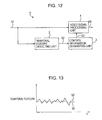
- Fig. 12 is a block diagram illustrating a basic configuration of a video signal processing apparatus which utilizes temporal features.
- a video signal processing apparatus 1 includes a temporal feature detecting unit 2, a control information generating unit 3, and a video signal processing unit 4.
- the temporal feature detecting unit 2 receives an input video signal S1 and detects a temporal feature S2.
- the control information generating unit 3 processes the temporal feature S2 and outputs control information S3 for controlling operations of the video signal processing unit 4.
- the video signal processing unit 4 processes the input video signal S1 and outputs an output video signal S4.
- the control information generating unit 3 processes the temporal feature S2 and generates the information control signal S3 on the basis of the temporal feature S2, so that the effect of the noise reduction processing increases with increasing noise in the input video signal S1.
- the control information generating unit 3 processes the temporal feature S2 and generates the information control signal S3 on the basis of the temporal feature S2, so that the effect of intra-field or intra-frame interpolation increases with increasing amount of motion contained in the input video signal S1.
- IP conversion refers to format conversion processing in which a video signal of an interlace format (interlace signal) is converted into a video signal of a progressive format (progressive signal) or vice versa.
- the video signal processing unit 4 performs format conversion on a video signal by interpolating a result of inter-field or inter-frame interpolation processing and a result of intra-field or intra-frame interpolation processing.
- the control information generating unit 3 controls an interpolation ratio applied to the interpolation operation using the information control signal S3.
- the temporal feature S2 detected by the temporal feature detecting unit 2 varies in time as illustrated in Fig. 13 .
- the effect of processing of the output video signal S4 varies in time along with the transition of the temporal feature S2.
- the visual quality of an image corresponding to the output video signal S4 is deteriorated.
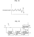
- a video signal processing apparatus 11 may be provided as illustrated in Fig. 15 .
- the video signal processing apparatus 11 includes a temporal feature smoothing unit 12.
- the temporal feature smoothing unit 12 smoothes a temporal feature S2 detected by a temporal feature detecting unit 2 and generates a smoothed temporal feature S5, as illustrated in Fig. 13 .
- a control information generating unit 3 uses the smoothed temporal feature S5 to generate control information S3.
- the video signal processing apparatus 11 prevents an abrupt temporary change in the effect of various processing in an output video signal S4.
- the temporal feature smoothing unit 12 may be implemented as, for example, an IIR (infinite impulse response) filter or an FIR (finite impulse response) filter.
- Japanese Unexamined Patent Application Publication No. 2002-15327 discloses a method in which a level of image enhancement is changed on the basis of a result of determination using a temporal feature as to whether or not an image is a natural image.
- Japanese Unexamined Patent Application Publication No. 2004-328635 discloses a technique relating to noise reduction processing. In this technique, a motion vector is used as a temporal feature and a reference value in measurement of a noise level is generated.
- Japanese Unexamined Patent Application Publication No. 2003-209716 discloses a method in which a noise level is measured from a temporal feature.
- Japanese Unexamined Patent Application Publication No. 2007-82040 discloses a method in which a field sequence associated with a 2-3 pulldown process is detected from a temporal feature and processing is switched in accordance with a detection result.
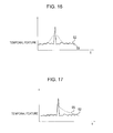
- the smoothed temporal feature S5 may fluctuate over a plurality of fields or frames due to a temporary change in the temporal feature S2 which is associated with a scene change or the like, as illustrated in Fig. 16 and Fig. 17 .
- This temporary change in the temporal feature S2 affects processing of a plurality of fields or frames, resulting in deterioration of image quality.
- Fig. 16 and Fig. 17 illustrate cases where an IIR filter and an FIR filter are implemented, respectively, as the temporal feature smoothing unit 12.
- the input video signal may be an interlace video signal generated by 2-3 pulldown.
- consecutive even fields or odd fields include fields corresponding to the same original frame, which are illustrated as fields A1 and fields C2 in Fig. 18 .
- processing of such an input video signal S1 when the temporal feature S2 across different frames are detected, no change in the temporal feature S2 will be detected between the fields A1 and between the fields C2.
- this also affects processing of a plurality of fields and frames, as in the case of a scene change, resulting in deterioration of the image quality.
- the present invention has been made in view of the above circumstances. Accordingly, there is a need for a video signal processing apparatus, a video signal processing method, a program for the video signal processing method, and a storage medium storing the video signal processing program, which can effectively prevent deterioration of image quality due to a temporary change in temporal features and perform stable processing on a video signal even if the video signal is generated by 2-3 pulldown (2-3 pulldown signal).
- a video signal processing apparatus includes a video signal processing unit configured to process an input video signal and output an output video signal, a temporal feature detecting unit configured to detect a temporal feature from the input video signal, a smoothing unit configured to smooth the temporal feature by filtering and output the smoothed temporal feature, and a controlling unit configured to control processing performed in the video signal processing unit on the basis of the smoothed temporal feature.
- the smoothing unit switches a characteristic of the filtering in accordance with the attribute of the input video signal.
- a video signal processing method includes the steps of processing an input video signal and outputting an output video signal, detecting a temporal feature from the input video signal, smoothing the temporal feature by filtering and outputting the smoothed temporal feature, and controlling processing performed in the processing step in accordance with the smoothed temporal feature.
- the smoothing step switches a characteristic of the filtering in accordance with the attribute of the input video signal.
- a program for a video signal processing method in which an input video signal is processed and an output video signal is generated includes the steps of processing the input video signal and generating the output video signal, detecting a temporal feature from the input video signal, smoothing the temporal feature by filtering and outputting the smoothed temporal feature, and controlling processing performed in the processing step in accordance with the smoothed temporal feature.
- the smoothing step switches a characteristic of the filtering in accordance with the attribute of the input video signal.
- a storage medium storing a program for a video signal processing method in which an input video signal is processed and an output video signal is generated includes the steps of processing the input video signal and generating the output video signal, detecting a temporal feature from the input video signal, smoothing the temporal feature by filtering and outputting the smoothed temporal feature, and controlling processing performed in the processing step in accordance with the smoothed temporal feature.
- the smoothing step switches a characteristic of the filtering in accordance with the attribute of the input video signal.
- an input video signal is processed by smoothing a temporal feature, and filtering characteristics relating to the smoothing processing are switched in accordance with the attribute of the input video signal.
- the filtering characteristics can be switched so that video signal processing is not affected by a temporal feature detected from fields corresponding to the same original frame in a 2-3 pulldown signal and by a temporal feature detected from fields associated with a scene change.
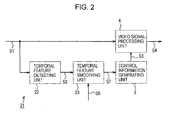
- FIG. 2 is a block diagram illustrating a video signal processing apparatus according to an embodiment of the present invention.
- a video signal processing apparatus 21 includes components similar to those included in the video signal processing apparatuses 1 and 11 illustrated in Fig. 12 and Fig. 15 , and these components are designated by the same reference numerals and the description thereof will be omitted herein.
- the video signal processing apparatus 21 in this embodiment is composed of a processor which processes an input video signal S1 by executing a predetermined program. In this embodiment, this program has been installed beforehand. However, it is also possible to execute the program stored in a storage medium such as an optical disk, a magnetic disk, and a memory card. The program may also be downloaded through a network such as the Internet.
- a temporal feature detecting unit 22 detects a temporal feature S2 from the input video signal S1 and then a temporal feature smoothing unit 23 smoothes the temporal feature S2 to generate a smoothed temporal feature S7.
- a video signal processing unit 4 processes the input video signal S1.
- the video signal processing unit 4 performs noise reduction processing on the input video signal S1.
- the temporal feature detecting unit 22 detects the temporal feature S2 represented by a value indicating an amount of noise.
- operation of the video signal processing unit 4 is controlled so that the effect of the noise reduction processing increases as the noise amount in the input video signal S1 increases.
- a delayed video signal generating section 25 generates a delayed video signal S11 by delaying the input video signal S1 by a predetermined delay time.
- this delay time may be a one frame period, i.e., a two-field period when the input video signal S1 is an interlace signal.
- the delay time may be a time period corresponding to a desired number of fields or frames as necessary.
- vertical filtering may be performed to correct vertical sampling phases which are different according to odd fields and even fields.
- motion correction may be performed on the input video signal S1 to generate the delayed video signal S11.
- the temporal feature detecting unit 22 also includes a difference signal generating section 26 and a difference-signal temporal feature detecting section 27.
- the difference signal generating section 26 is composed of a subtracter for subtracting the delayed video signal S11 from the input video signal S1 and outputting a difference signal S8.
- the difference-signal temporal feature detecting section 27 processes the difference signal S8 output from the difference signal generating section 26. Then, the difference-signal temporal feature detecting section 27 detects a temporal feature in the difference signal (difference-signal temporal feature S9) represented by a value indicating a noise amount, for each of blocks BL set by dividing one image of a field or frame of the input video signal S1 in the vertical and horizontal directions.
- a temporal feature in the difference signal (difference-signal temporal feature S9) represented by a value indicating a noise amount, for each of blocks BL set by dividing one image of a field or frame of the input video signal S1 in the vertical and horizontal directions.
- various statistical processing may be applied to the detection of the difference-signal temporal feature S9, including a mean square, a mean absolute value, a variance, a standard deviation, and a mean deviation of the difference signal S8.
- the blocks BL for the detection of the difference-signal temporal feature S9 may
- the temporal feature detecting unit 22 also includes an intra-image statistical processing section 28.
- the intra-image statistical processing section 28 performs statistical processing on the difference-signal temporal features S9 for each image of a field or a frame of the input video signal S1 to prevent degradation of detection precision due to motion of an object in an image.
- the intra-image statistical processing section 28 then outputs the temporal feature S2 indicating a noise amount in the entire image. Note that various processes may be applied to the statistical processing, including average processing, median processing, and processing utilizing distribution in a histogram, for preventing degradation of detection precision due to a moving object.
- Fig. 1 is a block diagram illustrating a configuration of the temporal feature smoothing unit 23.
- the temporal feature smoothing unit 23 includes a delayed temporal feature generating section 31, an order statistic filtering section 32, and a characteristic setting section 33.
- the delayed temporal feature generating section 31 sequentially delays the temporal feature S2 output from the temporal feature detecting unit 22 and outputs the delayed temporal feature S2 from a plurality of channels.
- the delayed temporal feature generating section 31 outputs a plurality of values of the temporal feature S2 of the input video signal S1 which are sequentially delayed by a predetermined number of fields or frames.
- the order statistic filtering section 32 selectively receives values of the temporal feature S2 corresponding to a predetermined number of taps from among the plurality of values of the temporal feature S2 output from the delayed temporal feature generating section 31 and the temporal feature S2 output from the temporal feature detecting unit 22. Then, the order statistic filtering section 32 sorts the input values of the temporal feature S2 in the order from the largest to the smallest. On the basis of the result of the sorting, the order statistic filtering section 32 selectively outputs the values of the temporal feature S2 from the largest one to the smallest one, thereby smoothing the temporal feature S2.
- the order statistic filtering section 32 switches the number of taps for the selective input of the temporal feature S2 from the delayed temporal feature generating section 31 and the order for the selective output of the temporal feature S2, in accordance with control performed by the characteristic setting section 33.
- the filtering characteristic used in the smoothing processing of the temporal feature S2 is switched by the control performed by the characteristic setting section 33.
- the characteristic setting unit 33 receives information on the attribute of the input video signal S1 (attribute information S6) and switches the setting of the order statistic filtering section 32 in accordance with the attribute information S6.
- the attribute information S6 is information for determining whether or not the input video signal S1 is a 2-3 pulldown signal and whether or not the input video signal S1 is an interlace signal.
- the video signal processing apparatus 21 is configured to process the input video signal S1 generated by decoding streaming data distributed by broadcast.
- the attribute information S6 may be identification information set in the header of the streaming data and meta-information of an EPG (electronic program guide).
- the characteristic setting section 33 determines whether the input video signal S1 is a video signal generated by interlace scanning or progressive scanning on the basis of the identification information set in the header of the streaming data.
- the characteristic setting section 33 determines whether or not the input video signal S1 is based on a movie film on the basis of the EPG meta-information.
- the characteristic setting section 33 determines the input video signal S1 based on a movie film to be a 2-3 pulldown signal.
- the attribute information may be information other than such header information and meta-information.
- the characteristic setting section 33 switches a characteristic of the order statistic filtering section 32 on the basis of a result of the above determination.
- the switching of the characteristic may be switching of the number of input taps for the filtering in the order statistic filtering section 32 and switching of the order of the data to be output from the order statistic filtering section 32.
- the characteristic setting section 33 sets the filtering characteristic in the order statistic filtering section 32 to five-tap input and sets the order statistic filtering section 32 to selectively output the third largest input value of the temporal feature S2.
- the delay time set in the delayed video signal generating section 25 is two fields, and thus a scene change affects the temporal feature S2 corresponding to consecutive two fields a1 and a2 illustrated in Fig. 6 .
- Fig. 6 illustrates consecutive fields of the input video signal S1 generated by 2-3 pulldown, each of which is designated by a reference character.
- the reference characters of fields which are generated from the same original film frame are enclosed by circles.
- the scene change affects the largest and second largest input values of the temporal feature S2 across five consecutive fields corresponding to the number of taps in the order statistic filtering section 32.
- the order statistic filtering section 32 performs filtering on the values of the input set of the temporal feature S2 other than the largest and second largest values, which are affected by the scene change.
- the order statistic filtering section 32 can perform filtering on the temporal feature S2 without being affected by the scene change, as illustrated in Fig. 7 .
- the temporal feature S2 is detected across different fields corresponding to the same original film frame, as illustrated in Fig. 6 .
- the third largest input value of the temporal feature S2 is output so that filtering is performed by omitting values of the temporal feature S2 corresponding to the same original frame which exhibit a temporary decrease.
- the number of input taps of the order statistic filtering section 32 is set to five. However, it is also possible to set more than five taps as the input taps of the order statistic filtering section 32 to achieve a similar processing effect.
- the characteristic setting section 33 switches the number of input taps of the order statistic filtering section 32 to be three, so that the order statistic filtering section 32 outputs the smallest input value of the temporal feature S2.
- the characteristic setting section 33 switches the number of the input taps of the order statistic filtering section 32 to two, so that the order statistic filtering section 32 outputs the smallest input value of the temporal feature S2.
- the order statistic filtering section 32 may be configured to have a characteristic of a median filter having three or more taps.
- the temporal feature detecting unit 22 detects the temporal feature S2 from the input video signal S1, and the control information generating unit 3 generates control information S3 on the basis of the temporal feature S2. Then, on the basis of the control information S3, the video signal processing unit 4 reduces noise in the input video signal S1 and outputs the output video signal S4. With this processing, the video signal processing apparatus 21 can dynamically switch the processing to be performed on the input video signal S1 on the basis of the temporal feature S2 of the input video signal S1.
- the temporal feature S2 is smoothed by the temporal feature smoothing unit 23 and then the control information S3 is generated by the control information generating unit 3 on the basis of the smoothed temporal feature S7.
- This arrangement can prevent a variation in the effect of noise reduction due to a variation in the temporal feature S2 and also prevent deterioration of visual image quality.
- the temporal feature S2 is sequentially delayed in the delayed temporal feature generating section 31 of the temporal feature smoothing unit 23 ( Fig. 1 ). Then, values of the delayed temporal feature S2 output from a plurality of channels are filtered by the order statistic filtering section 32.
- the attribute of the input video signal S1 is determined by the characteristic setting section 33, and on the basis of the determination result, the characteristic of the filtering performed in the order statistic filtering section 32 is switched.
- the temporal feature S2 in processing of the input video signal S1, such as a 2-3 pulldown signal, an interlace signal, and a progressive signal, the temporal feature S2 can be smoothed by omitting values of the temporal feature S2 detected from the fields corresponding to the same original film frame in the 2-3 pulldown signal and values of the temporal feature S2 detected from fields associated with a scene change (as illustrated in Fig. 6 and Fig. 7 ).
- the characteristic of filtering performed on the temporal feature S2 can be switched in accordance with the attribute of the input video signal S1.
- deterioration of the image quality due to a temporary change in the temporal feature S2 can be effectively prevented, and thus stable video signal processing can be achieved.
- the difference-signal temporal feature detecting section 27 detects the difference-signal temporal feature S9 for each of blocks on an image, from the difference signal S8 corresponding to a difference between consecutive even fields and consecutive odd fields. Then, values of difference-signal temporal feature S9 are statistically processed by the intra-image statistical processing section 28, and the temporal feature S2 indicating a noise amount is detected for each field.
- the delay time for the detection of the temporal feature S2 is two fields.
- the third largest input value is selected from among the input values of the temporal feature S2 across five consecutive fields, which are respectively input to five taps (i.e., the median of the values of the temporal feature S2).
- the selected median temporal feature S2 is output as the smoothed temporal feature S7.
- the input video signal S1 may not be a 2-3 pulldown signal.
- the characteristic of the order statistic filtering section 32 is set such that the number of taps is three for an interlace signal or two for a progressive signal, for example and the smallest value is output. This prevents deterioration of image quality associated with a scene change without excessive smoothing processing of the temporal feature S2. With appropriate smoothing processing of temporal feature S2, deterioration of image quality due to a variation in the temporal feature S2 can also be prevented.
- detecting a temporal feature from a difference signal of an input video signal allows dynamic switching of noise reduction processing in accordance with the attribute of the input video signal, so that the noise in the input video signal can be adequately reduced.
- the temporal feature is detected from the difference signal of the input video signal in units of blocks on an image of a field of a frame, and then statistical processing is performed on the values of the temporal feature corresponding to the individual blocks, for each image of a frame or field. With this arrangement, the temporal feature can be readily detected for each image.
- an order statistic filter as a smoothing filter
- the filtering characteristics related to smoothing processing on the temporal feature can be switched by simply switching the number of input taps and the order for selective output of values of the temporal feature.
- Fig. 8 is a block diagram illustrating a configuration of a temporal feature detecting unit implemented in a video signal processing apparatus according to a second embodiment of the present invention.
- the video signal processing apparatus in this embodiment have the same configuration as the video signal processing apparatus illustrated in Fig. 3 described above, except that it has a temporal feature detecting unit 42 instead of the temporal feature detecting unit 22, as illustrated in Fig. 8 .
- a temporal feature of an input video signal S1 is detected by an intra-image feature detecting section 43.
- the detected feature is delayed by one frame by a delayed intra-image feature generating section 44.
- a difference-signal feature detecting section 45 subtracts the delayed feature from the feature output from the intra-image feature detecting section 43 in units of blocks so that a temporal feature S9 is detected in units of blocks.
- a temporal feature S2 is generated from an inter-frame difference or an inter-field difference of in the feature detected from the input video signal S1.
- the intra-image feature detecting section 43 a variance and a mean deviation of pixel values, and energy of high-pass filter output, etc. are detected for each of the blocks BL described in Fig. 4 and Fig. 5 .
- the temporal feature S2 similar to the temporal feature S2 in the first embodiment can be detected through the difference signal feature detecting section 45.
- a feature of the input video signal S1 is first detected in units of blocks, and then a temporal feature is detected on the basis of an inter-field difference or an inter-frame difference.
- a processing effect similar to the first embodiment can be obtained with a reduced capacity of a memory used for generating delayed signals.
- Fig. 9 is a block diagram illustrating a video signal processing apparatus according to a third embodiment the present invention.
- an area dividing unit 53 outputs an input video signal S1 from a plurality of channels corresponding to individual areas AR set in the input video signal S1.
- Area processing units 54A to 54N are each configured similarly to the video signal processing apparatuses according to the first and second embodiments described above.
- Each of the area processing units 54A to 54N detects a temporal feature in a corresponding area AR and reduces noise in the area AR in the input video signal S1 on the basis of the detected temporal feature.
- the areas AR are obtained by dividing each of the blocks BL illustrated in Fig. 4 and Fig. 5 , as illustrated in Fig. 10 and Fig. 11 .
- An area integrating unit 55 integrates the input video signal S1 in the plurality of channels, in which the noise in each area AR is reduced, into one-channel signal and outputs an output video signal S4.
- the attribute information of the input video signal S1 is input for each of the channels of the input video signal S1 and a characteristic of filtering relating to smoothing processing is switched. Specifically, when two images are displayed by, for example, picture-in-picture display, the attribute information of a video signal from which the input video signal S1 is generated is supplied for each of areas in the individual displayed images.
- the noise reduction processing can be dynamically switched and the filtering characteristic relating to smoothing of the temporal feature can be switched in accordance with the individual the attribute of the input video signal S1. This can further prevent deterioration of image quality and enhance noise reduction processing.
- the filtering characteristic relating to smoothing of a temporal feature can be appropriately switched for each area. This increases stability of video signal processing.
- signal processing to be performed on an input video signal is noise reduction.
- the present invention is not limited to this case and applied to various video signal processing utilizing temporal features.
- the present invention may be applied to cases where a value indicating the amount of noise is used as a temporal feature and image enhancement is performed on an input video signal using a video signal processing unit, where a value indicating the amount of motion is used as a temporal feature and IP conversion of an input video signal is performed, and where a value indicating an activity level or the like corresponding to an encoding difficulty is used as a temporal feature and MPEG encoding is performed on an input video signal using a video signal processing unit.
- the amount of allocated codes may increase with increasing temporal feature.
- abrupt changes in a temporal feature due to a scene change and 2-3 pulldown are taken into account.
- the present invention is not limited to this case and can be applied to a case where an abrupt change in a temporal feature due to a flash or the like is taken into account.
- a video signal processing apparatus is composed of a processor.
- the present invention is not limited to this case, and it is also possible to implement a video signal processing apparatus by hardware.
Landscapes
- Engineering & Computer Science (AREA)
- Multimedia (AREA)
- Signal Processing (AREA)
- Picture Signal Circuits (AREA)
- Television Systems (AREA)
Applications Claiming Priority (1)
| Application Number | Priority Date | Filing Date | Title |
|---|---|---|---|
| JP2007126233A JP5050637B2 (ja) | 2007-05-11 | 2007-05-11 | 映像信号処理装置、映像信号処理方法、映像信号処理方法のプログラム及び映像信号処理方法のプログラムを記録した記録媒体 |
Publications (2)
| Publication Number | Publication Date |
|---|---|
| EP1991005A2 true EP1991005A2 (fr) | 2008-11-12 |
| EP1991005A3 EP1991005A3 (fr) | 2016-10-12 |
Family
ID=39711794
Family Applications (1)
| Application Number | Title | Priority Date | Filing Date |
|---|---|---|---|
| EP08251390.4A Withdrawn EP1991005A3 (fr) | 2007-05-11 | 2008-04-10 | Appareil, procédé et programme pour traitement de signal vidéo pour le filtrage temporel d'un signal vidéo avant le traitement d'image du signal vidéo |
Country Status (3)
| Country | Link |
|---|---|
| US (1) | US9100663B2 (fr) |
| EP (1) | EP1991005A3 (fr) |
| JP (1) | JP5050637B2 (fr) |
Cited By (1)
| Publication number | Priority date | Publication date | Assignee | Title |
|---|---|---|---|---|
| EP2761597A4 (fr) * | 2011-10-01 | 2015-07-01 | Intel Corp | Systèmes, procédés, et progiciels de post-traitement et de prétraitement intégrés au transcodage vidéo |
Families Citing this family (3)
| Publication number | Priority date | Publication date | Assignee | Title |
|---|---|---|---|---|
| JP4739295B2 (ja) * | 2007-08-27 | 2011-08-03 | 日本電信電話株式会社 | 映像信号生成装置、映像信号生成方法、映像信号生成プログラムおよびそのプログラムを記録したコンピュータ読み取り可能な記録媒体 |
| JP2014241457A (ja) * | 2011-10-04 | 2014-12-25 | シャープ株式会社 | シーンチェンジ検出装置、表示装置、シーンチェンジ検出方法およびシーンチェンジ検出プログラム |
| WO2013129158A1 (fr) | 2012-03-01 | 2013-09-06 | ソニー株式会社 | Émetteur, procédé d'émission et récepteur |
Citations (5)
| Publication number | Priority date | Publication date | Assignee | Title |
|---|---|---|---|---|
| JP2002015327A (ja) | 2000-06-28 | 2002-01-18 | Sony Corp | 画像種別判別装置およびこれを用いた画像処理装置ならびに画像種別判別方法。 |
| JP2003209716A (ja) | 2002-01-16 | 2003-07-25 | Sony Corp | 映像信号処理装置および方法、記録媒体、並びにプログラム |
| JP2004328635A (ja) | 2003-04-28 | 2004-11-18 | Sony Corp | 信号処理装置および信号処理方法 |
| JP2007082040A (ja) | 2005-09-16 | 2007-03-29 | Sony Corp | 信号処理装置および方法、プログラム、並びに記録媒体 |
| JP2007126233A (ja) | 2005-11-01 | 2007-05-24 | Canon Finetech Inc | シート処理装置および画像形成装置 |
Family Cites Families (22)
| Publication number | Priority date | Publication date | Assignee | Title |
|---|---|---|---|---|
| JP3106707B2 (ja) * | 1992-07-09 | 2000-11-06 | 松下電器産業株式会社 | ワイド画面対応撮像装置 |
| JP3824678B2 (ja) * | 1995-05-09 | 2006-09-20 | 株式会社ルネサステクノロジ | 画像復号表示装置 |
| US5631706A (en) * | 1995-06-07 | 1997-05-20 | Mitsubishi Consumer Electronics America, Inc. | Converter and method for converting video signals of interlace format to video signals of progressive format |
| US6061100A (en) * | 1997-09-30 | 2000-05-09 | The University Of British Columbia | Noise reduction for video signals |
| JP4038858B2 (ja) * | 1998-01-28 | 2008-01-30 | ソニー株式会社 | 信号処理装置及び方法 |
| JP4292637B2 (ja) * | 1999-08-20 | 2009-07-08 | ソニー株式会社 | 信号処理装置及び方法 |
| US6871003B1 (en) * | 2000-03-17 | 2005-03-22 | Avid Technology, Inc. | Edit decision list for identifying the pull down phase of a video signal |
| US6940557B2 (en) * | 2001-02-08 | 2005-09-06 | Micronas Semiconductors, Inc. | Adaptive interlace-to-progressive scan conversion algorithm |
| JP2002320111A (ja) * | 2001-04-23 | 2002-10-31 | Matsushita Electric Ind Co Ltd | 階調補正装置 |
| US6859235B2 (en) * | 2001-05-14 | 2005-02-22 | Webtv Networks Inc. | Adaptively deinterlacing video on a per pixel basis |
| US7110455B2 (en) * | 2001-08-14 | 2006-09-19 | General Instrument Corporation | Noise reduction pre-processor for digital video using previously generated motion vectors and adaptive spatial filtering |
| US7068722B2 (en) * | 2002-09-25 | 2006-06-27 | Lsi Logic Corporation | Content adaptive video processor using motion compensation |
| US7489829B2 (en) * | 2003-03-11 | 2009-02-10 | Sightic Vista Ltd. | Adaptive low-light image processing |
| JP4453805B2 (ja) * | 2003-03-25 | 2010-04-21 | セイコーエプソン株式会社 | 画像処理システム、プロジェクタ、プログラム、情報記憶媒体および画像処理方法 |
| KR100564592B1 (ko) * | 2003-12-11 | 2006-03-28 | 삼성전자주식회사 | 동영상 데이터 잡음제거방법 |
| JP4265986B2 (ja) * | 2004-03-22 | 2009-05-20 | 富士フイルム株式会社 | 画像処理方法および装置並びにプログラム |
| WO2005117474A1 (fr) | 2004-05-24 | 2005-12-08 | Kodiak Networks, Inc. | Module d'identite d'abonne (sim) permettant des services vocaux evolues (avs) notamment le bouton de microphone, bouton de conference et bouton de message sur des combines et des reseaux sans fil |
| CN100473111C (zh) * | 2004-05-25 | 2009-03-25 | 皇家飞利浦电子股份有限公司 | 增强视频信号锐度的方法和系统 |
| JP4534723B2 (ja) * | 2004-11-05 | 2010-09-01 | 株式会社日立製作所 | 画像表示装置、画像処理装置および画像処理方法 |
| TWI296090B (en) * | 2004-11-30 | 2008-04-21 | Realtek Semiconductor Corp | Apparatus and method for image adjustment |
| JP2006270417A (ja) * | 2005-03-23 | 2006-10-05 | Victor Co Of Japan Ltd | 映像信号処理方法及び映像信号処理装置 |
| KR101108435B1 (ko) * | 2005-05-31 | 2012-02-16 | 서강대학교산학협력단 | 의사윤곽 제거 방법 및 이 방법이 적용되는 디스플레이장치 |
-
2007
- 2007-05-11 JP JP2007126233A patent/JP5050637B2/ja not_active Expired - Fee Related
-
2008
- 2008-04-10 EP EP08251390.4A patent/EP1991005A3/fr not_active Withdrawn
- 2008-04-28 US US12/110,909 patent/US9100663B2/en not_active Expired - Fee Related
Patent Citations (5)
| Publication number | Priority date | Publication date | Assignee | Title |
|---|---|---|---|---|
| JP2002015327A (ja) | 2000-06-28 | 2002-01-18 | Sony Corp | 画像種別判別装置およびこれを用いた画像処理装置ならびに画像種別判別方法。 |
| JP2003209716A (ja) | 2002-01-16 | 2003-07-25 | Sony Corp | 映像信号処理装置および方法、記録媒体、並びにプログラム |
| JP2004328635A (ja) | 2003-04-28 | 2004-11-18 | Sony Corp | 信号処理装置および信号処理方法 |
| JP2007082040A (ja) | 2005-09-16 | 2007-03-29 | Sony Corp | 信号処理装置および方法、プログラム、並びに記録媒体 |
| JP2007126233A (ja) | 2005-11-01 | 2007-05-24 | Canon Finetech Inc | シート処理装置および画像形成装置 |
Cited By (1)
| Publication number | Priority date | Publication date | Assignee | Title |
|---|---|---|---|---|
| EP2761597A4 (fr) * | 2011-10-01 | 2015-07-01 | Intel Corp | Systèmes, procédés, et progiciels de post-traitement et de prétraitement intégrés au transcodage vidéo |
Also Published As
| Publication number | Publication date |
|---|---|
| EP1991005A3 (fr) | 2016-10-12 |
| JP2008283503A (ja) | 2008-11-20 |
| JP5050637B2 (ja) | 2012-10-17 |
| US20080278630A1 (en) | 2008-11-13 |
| US9100663B2 (en) | 2015-08-04 |
Similar Documents
| Publication | Publication Date | Title |
|---|---|---|
| US20050249282A1 (en) | Film-mode detection in video sequences | |
| US5847772A (en) | Adaptive filter for video processing applications | |
| KR100497606B1 (ko) | 블럭노이즈 검출장치 및 블럭노이즈 제거장치 | |
| US8218083B2 (en) | Noise reducer, noise reducing method, and video signal display apparatus that distinguishes between motion and noise | |
| US8305489B2 (en) | Video conversion apparatus and method, and program | |
| EP1480166A1 (fr) | Procédé et système d'accentuation des bords | |
| WO2017160606A1 (fr) | Abandon opportuniste de trame pour codage à fréquence de trame variable | |
| US10096093B2 (en) | Object speed weighted motion compensated interpolation | |
| US10440318B2 (en) | Motion adaptive de-interlacing and advanced film mode detection | |
| JP5137687B2 (ja) | 復号装置及び復号方法、プログラム | |
| EP2227902A1 (fr) | Appareil et procédé de génération de trame d'interpolation et appareil de réception de radiodiffusion | |
| US9100663B2 (en) | Apparatus, method, and program for video signal processing, and storage medium | |
| US20050259950A1 (en) | Film mode correction in still areas | |
| EP2723066A3 (fr) | Désentrelacement vidéo adaptatif spatio-temporel | |
| US8213718B2 (en) | Method for video mode detection | |
| JP2006128744A (ja) | ブロック歪み低減装置 | |
| US7817209B2 (en) | Video signal processing device and video signal processing method | |
| KR20050012773A (ko) | 샤프니스 예측 드리프트를 줄이기 위한 후-처리를 가지는비디오 디코딩 시스템 및 방법 | |
| EP0772351B1 (fr) | Détection de mouvement pour signaux vidéo entrelacés | |
| JP4500112B2 (ja) | 画像特徴量検出装置、画質改善装置、表示装置および受信機 | |
| JP2007336075A (ja) | ブロック歪み低減装置 | |
| JP5300568B2 (ja) | 映像処理装置およびその制御方法 | |
| JP2005236955A (ja) | ブロックノイズ低減装置 | |
| JP2000023166A (ja) | 動画像符号化処理装置 | |
| JP4186769B2 (ja) | Gop周期検出装置 |
Legal Events
| Date | Code | Title | Description |
|---|---|---|---|
| PUAI | Public reference made under article 153(3) epc to a published international application that has entered the european phase |
Free format text: ORIGINAL CODE: 0009012 |
|
| 17P | Request for examination filed |
Effective date: 20080410 |
|
| AK | Designated contracting states |
Kind code of ref document: A2 Designated state(s): AT BE BG CH CY CZ DE DK EE ES FI FR GB GR HR HU IE IS IT LI LT LU LV MC MT NL NO PL PT RO SE SI SK TR |
|
| PUAL | Search report despatched |
Free format text: ORIGINAL CODE: 0009013 |
|
| AK | Designated contracting states |
Kind code of ref document: A3 Designated state(s): AT BE BG CH CY CZ DE DK EE ES FI FR GB GR HR HU IE IS IT LI LT LU LV MC MT NL NO PL PT RO SE SI SK TR |
|
| RIC1 | Information provided on ipc code assigned before grant |
Ipc: H04N 5/21 20060101AFI20160906BHEP |
|
| 17Q | First examination report despatched |
Effective date: 20160923 |
|
| STAA | Information on the status of an ep patent application or granted ep patent |
Free format text: STATUS: THE APPLICATION IS DEEMED TO BE WITHDRAWN |
|
| AKX | Designation fees paid |
Designated state(s): DE FR GB NL |
|
| 18D | Application deemed to be withdrawn |
Effective date: 20170204 |