EP1991129B1 - Systeme pour le traitement de la peau par onde acoustique de surface - Google Patents
Systeme pour le traitement de la peau par onde acoustique de surface Download PDFInfo
- Publication number
- EP1991129B1 EP1991129B1 EP07861247.0A EP07861247A EP1991129B1 EP 1991129 B1 EP1991129 B1 EP 1991129B1 EP 07861247 A EP07861247 A EP 07861247A EP 1991129 B1 EP1991129 B1 EP 1991129B1
- Authority
- EP
- European Patent Office
- Prior art keywords
- skin
- actuator
- saw
- wound
- surface acoustic
- Prior art date
- Legal status (The legal status is an assumption and is not a legal conclusion. Google has not performed a legal analysis and makes no representation as to the accuracy of the status listed.)
- Active
Links
Images








Classifications
-
- A—HUMAN NECESSITIES
- A61—MEDICAL OR VETERINARY SCIENCE; HYGIENE
- A61L—METHODS OR APPARATUS FOR STERILISING MATERIALS OR OBJECTS IN GENERAL; DISINFECTION, STERILISATION OR DEODORISATION OF AIR; CHEMICAL ASPECTS OF BANDAGES, DRESSINGS, ABSORBENT PADS OR SURGICAL ARTICLES; MATERIALS FOR BANDAGES, DRESSINGS, ABSORBENT PADS OR SURGICAL ARTICLES
- A61L2/00—Disinfection or sterilisation of materials or objects, in general; Accessories therefor
- A61L2/02—Disinfection or sterilisation of materials or objects, in general; Accessories therefor using physical processes
- A61L2/025—Ultrasonic waves
-
- A—HUMAN NECESSITIES
- A61—MEDICAL OR VETERINARY SCIENCE; HYGIENE
- A61H—PHYSICAL THERAPY APPARATUS, e.g. DEVICES FOR LOCATING OR STIMULATING REFLEX POINTS IN THE BODY; ARTIFICIAL RESPIRATION; MASSAGE; BATHING DEVICES FOR SPECIAL THERAPEUTIC OR HYGIENIC PURPOSES OR SPECIFIC PARTS OF THE BODY
- A61H23/00—Percussion or vibration massage, e.g. using supersonic vibration; Suction-vibration massage; Massage with moving diaphragms
- A61H23/02—Percussion or vibration massage, e.g. using supersonic vibration; Suction-vibration massage; Massage with moving diaphragms with electric or magnetic drive
- A61H23/0218—Percussion or vibration massage, e.g. using supersonic vibration; Suction-vibration massage; Massage with moving diaphragms with electric or magnetic drive with alternating magnetic fields producing a translating or oscillating movement
- A61H23/0236—Percussion or vibration massage, e.g. using supersonic vibration; Suction-vibration massage; Massage with moving diaphragms with electric or magnetic drive with alternating magnetic fields producing a translating or oscillating movement using sonic waves, e.g. using loudspeakers
-
- A—HUMAN NECESSITIES
- A61—MEDICAL OR VETERINARY SCIENCE; HYGIENE
- A61L—METHODS OR APPARATUS FOR STERILISING MATERIALS OR OBJECTS IN GENERAL; DISINFECTION, STERILISATION OR DEODORISATION OF AIR; CHEMICAL ASPECTS OF BANDAGES, DRESSINGS, ABSORBENT PADS OR SURGICAL ARTICLES; MATERIALS FOR BANDAGES, DRESSINGS, ABSORBENT PADS OR SURGICAL ARTICLES
- A61L2/00—Disinfection or sterilisation of materials or objects, in general; Accessories therefor
- A61L2/24—Apparatus using programmed or automatic operation
-
- A—HUMAN NECESSITIES
- A61—MEDICAL OR VETERINARY SCIENCE; HYGIENE
- A61H—PHYSICAL THERAPY APPARATUS, e.g. DEVICES FOR LOCATING OR STIMULATING REFLEX POINTS IN THE BODY; ARTIFICIAL RESPIRATION; MASSAGE; BATHING DEVICES FOR SPECIAL THERAPEUTIC OR HYGIENIC PURPOSES OR SPECIFIC PARTS OF THE BODY
- A61H2201/00—Characteristics of apparatus not provided for in the preceding codes
- A61H2201/10—Characteristics of apparatus not provided for in the preceding codes with further special therapeutic means, e.g. electrotherapy, magneto therapy or radiation therapy, chromo therapy, infrared or ultraviolet therapy
- A61H2201/105—Characteristics of apparatus not provided for in the preceding codes with further special therapeutic means, e.g. electrotherapy, magneto therapy or radiation therapy, chromo therapy, infrared or ultraviolet therapy with means for delivering media, e.g. drugs or cosmetics
-
- A—HUMAN NECESSITIES
- A61—MEDICAL OR VETERINARY SCIENCE; HYGIENE
- A61M—DEVICES FOR INTRODUCING MEDIA INTO, OR ONTO, THE BODY; DEVICES FOR TRANSDUCING BODY MEDIA OR FOR TAKING MEDIA FROM THE BODY; DEVICES FOR PRODUCING OR ENDING SLEEP OR STUPOR
- A61M25/00—Catheters; Hollow probes
- A61M2025/0019—Cleaning catheters or the like, e.g. for reuse of the device, for avoiding replacement
Definitions
- the present invention relates to the methods and devices creating surface acoustic waves on human skin surfaces and directing them to particular places of interest for therapeutic needs, wound healing, disinfecting and anti-agent applications.
- Ultrasonic waves have been widely used in medical applications, including diagnostics and therapy, and in many industrial applications, for welding, cutting, fiber optics technology, speed meters, etc.
- Diagnostic use of ultrasound waves includes using ultrasonic waves to detect underlying structures in an object or human body.
- An ultrasonic transducer is placed in contact with the tissue or object via a coupling medium, and high frequency (1-10 MHz) ultrasonic waves are directed to the tissue.
- the waves are reflected back to a receiver adjacent the transducer.
- an image of the underlying structure can be produced.
- ultrasound waves Three therapeutic medical uses of ultrasound waves include aerosol mist production, contact physiotherapy, and soft tissue ablation.
- the ultrasound contact physiotherapy procedure may cause a patient significant discomfort and/or pain, and skin may appear raw and damaged.
- a treatment device according to the preamble of claim 1 is known from the US Patent Application Publication No. 2004/0236268 A1 .
- the present invention is directed to methods for treating the surfaces of human skin and underlying layers with surface acoustic waves (SAW) of Rayleigh, "pseudo" Rayleigh, or Lamb type.
- SAW surface acoustic waves
- the present invention can be used to achieve rejuvenation, local improvement of the blood circulation, heating of the tissue, accelerated enzyme activity, muscle relaxation, pain reduction, and enhancement of natural healing processes.
- wound for the purposes of "wound healing", as used throughout the present application, includes ulcers such as venous ulcers as well as burns, ulcerated wounds due to, for example, diabetes, surgical incisions or other surgical cuttings including stitched surgical cuttings, skin grafts, hair transplants, re-vascularization, bed sores, tissue dehiscence, and ligament and tendon repair and reconstruction.
- wound healing encompasses addressing damage to, repair of, or restoration of soft tissue.
- Conventional ultrasound used for therapy may be of high frequency (1-4 MHz) and low frequency (20-120 KHz), and may have longitudinal or transverse characteristics.
- the present application discloses excitement of surface acoustic waves on the skin (low-power, low-frequency) and employment of this phenomenon for therapeutic needs.
- low-power, low-frequency ultrasound (20-120 kHz, 0.05-1.0 W/cm 2 ) propagated in the form of surface acoustic waves is effective in one or more of the following: inhibiting adhesion, micro-massage, healing processes, tissue fluid interchange, increased growth of capillary, increased pH of tissue liquids, lowered pain syndrome, resistance of thrombus formation, better drug administering, reduced friction, the cleansing of tissue, the removal of necrotic debris, disinfection, the "biostimulation" of cells, blood flow, micromassaging, drying, intensity of drug diffusion, activeness of the coating agents, and wound healing.
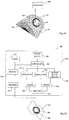
- FIG. 1A is a schematic illustration of an actuator 200 for producing surface acoustic waves positioned on an external surface 110 of a portion of skin 402, in accordance with embodiments of the present invention.
- Actuator 200 is in electrical communication with a processor 300.
- Processor 300 may be, for example, a central processing unit (CPU), and may include an oscillator, an amplifier, and any other component used for receiving and transmitting signals and making calculations related to the received and transmitted signals.
- actuator 200 Upon receipt of an electrical signal from processor 300, actuator 200 is capable of generating high frequency mechanical vibrations, in a range from KHz to MHz.
- SAW surface acoustic waves
- the frequency of generated mechanical oscillations in actuator 200 is directly related to the frequency produced by processor 300.
- the energy source applied via processor 300 may have a periodical or non-periodical character, and may be electro-mechanical, electromagnetic, or electro-optical.
- Actuator 200 may be comprised of one or multiple piezoelectric transducers, one or more electromagnetic acoustic transducers, or one or multiple laser pulse transducers. In the case of piezoelectric and electromagnetic transducers, direct contact between actuator 200 and skin 402 is necessary. In the case of laser pulse transducers, non-contact methods may be employed.
- SAW surface acoustic waves
- actuator 200 is configured to transmit electrical signals proportional to the mechanical energy created to processor 300, and may thus provide a feedback loop to regulate the electrical signals produced by processor 300.
- Coupler 502 may optionally be placed between actuator 200 and skin 402 in order to match acoustic signal transmission properties of materials of skin 402 and actuator 200.
- signals are sent from actuator 200 to processor 300.
- these signals are received by a receiver 310 within processor 300.
- signals are sent by a separate sensor placed on or near or incorporated within actuator 200, as will be described in further detail hereinbelow.
- Signals received by receiver 310 are sent to a memory module 312, where they are compared with expected values. Results of the comparison are then either sent to controller 303, where signal parameters such as amplitude and frequency may be automatically adjusted based on the received information, or sent to an alarm 311 for alerting a user that parameters should be adjusted manually.
- frequencies may be in a range of 0.1 Hz - 10 MHz.
- frequencies may be in a range of 1KHz-20KHz so as to provide higher energy waves that can penetrate the interface.
- higher energy may be accomplished by modulation of waves to produce increased amplitudes.
- Pulsed or continuous inputs may be used.
- types of waves may differ as well. For example, acne may be treated by focused waves, as will be described in further detail hereinbelow, while micro-massage may be accomplished via a large range of wave types.
- Microstreaming may also be accomplished via a large range of wave types; however, the speed of microstreaming may vary based on the chosen parameters. Speed of microstreaming may be in a range of 1 nm/minute to 10 microns/minute.
- Different energy penetration depths to the skin layers may be achieved because different energy picks on the surface of the plate may be excited changing one or more: the energy level of the driver, piezo element excitement frequency, vibration characteristics m and n (as will discussed with regard to FIGS. 7 and 8 ).
- FIG. 3A is a schematic representation (not to scale) showing the propagation of a Rayleigh wave on an elastic surface.
- the physical motion of this "true-SAW" wave type is associated with mechanically time-dependent elliptical displacement of the surface structure.
- One component of the physical displacement is parallel to the SAW propagation axis X, and another component is normal to the surface along axis Y.
- the amplitude of surface displacement along the y-axis is larger than along the SAW propagation axis X.
- the amplitudes of both SAW displacement components are negligible for penetration depths (into the body of the solid, such as, for example skin 402) greater than a few acoustic wavelengths.
- Lamb waves Propagation of Lamb waves depends on density, elastic, and other material properties of the solid (such as skin 402, for example), and they are influenced a great deal by selected frequency and material thickness.
- Lamb waves a number of modes of particle vibration are possible, but the two most common are symmetrical and antisymmetrical.
- the complex motion of the particles is similar to the elliptical orbits for surface waves.
- FIG. 3B is a schematic illustration showing the generation of a compressional wave into fluid ⁇ 1 by a SAW having a wavelength ⁇ and delivered at an angle ⁇ to external surface 110 of skin 402.
- Pressure gas or fluid loading
- attenuation is due to the generation of compressional waves in the gas or fluid in contact with a surface of skin 402.
- the shear vertical component of the wave causes periodic compression and rarefaction of the gas or fluid, resulting in a coupling of acoustic energy from skin 402 into the gas or fluid.
- SAW Stimulation of materials on these surfaces, including fluids and particulates suspended therein.
- the SAW may reduce the existing biofilm, augment and enhance the effect of antibiotics on the biofilm (i.e. decrease the biofilm's resistance to antibiotics), produce antimicrobial and antithrombogenic surfaces, and augment tissue therapy.
- FIG. 4 is a cross-sectional illustration of a skin 402 with an actuator 200 attached thereto, wherein actuator 200 is comprised of an electromagnetic transducer 201.
- actuator 200 is comprised of a base portion 280 and an activating portion 282.
- Base portion 280 may be of any conductive material, such as a metal and activating portion 282 is comprised of electromagnetic transducers, such as electromagnetic ultrasound transducers available from Olympus company, Panametrics-NDT Ultrasonic Transducer.
- Base portion 280 may be the face of electromagnetic transducer. We may get the SAW in the desired range, by choosing the frequency of the electromagnetic transducer.
- Activating portion 282 is configured to excite Lamb waves in plates. This type of actuator vibrates the atoms within skin 402.
- Processor 300 is in electrical communication with base portion 280.
- Processor 300 applies a current to base portion 280, which is comprised of an electrically conductive material.
- base portion 280 which is comprised of an electrically conductive material.
- FIG. 5 is a diagrammatic illustration of skin 402 with a processor 300, wherein processor 300 is a pulsed laser device 301.
- Actuator 200 is a metallic plate which is configured to vibrate in response to laser pulses from processor 300. No contact is necessary between actuator 200 and processor 200 since laser pulses travel through the air.
- Pulsed laser device 301 is used to generate SAW 121 in solids by a thermoelastic mechanism, wherein the resulting elastic displacement waveform has a wide band.
- the frequency range of the SAW excited using pulsed lasers has limited bandwidth as only short pulse widths may be excited with pulsed laser device 301 in a solid.
- the amplitude and the frequency bandwidth of the laser-induced SAW are improved by decreasing the radius of the focused laser spot. For example, laser pulse focused to a line produced by Max-Planck-Institute for Solid State Research may be applied.
- Actuator 200 may include one or more piezo-actuators 203, which are configured to provide SAW in accordance with embodiments of the present invention. These piezo-actuators 203 are configured to provide vibrations at amplitudes of between 0.2-2 nanometers.
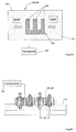
- FIGS. 6A-6C are illustrations of actuator 200, wherein actuator 200 is comprised of one or multiple piezo-elements 203.
- Actuator 200 may include a base portion 280 and an activating portion 282, wherein activating portion 282 is comprised of piezo-elements 203.
- electrodes must be included on piezo-elements 203. In many of the figures, these electrodes are not shown since they may be placed in any location, and the different possibilities for positioning of electrodes are known to those skilled in the art.
- base portion 280 is also the activating portion 282 and is thus comprised of piezo-elements 203. As shown in FIG.
- actuator 200 is an integrated piezo-transducer, also known as an interdigital transducer (IDT) 205, having multiple elongated portions 206 or fingers, generating SAW on surfaces of skin 402 when the distance L between two of elongated portions 206 is proportional to one-half the length of the SAW.
- IDT interdigital transducer
- the IDT 205 comprises a base portion 280 which also may act as activating portion 282.
- Activating portion 282 includes a piezoelectric material with an electrode portion 284 sprayed thereon in a particular configuration such as the one shown in FIG. 6B . It should be noted that the configuration shown in FIG. 6B represents three different possible setups for IDT 205.
- base portion 280 is comprised of a piezoelectric material and acts as activating portion 282, with electrode portion 284 sprayed thereon in a "W" configuration as shown or in any known configuration for IDT.
- base portion 280 is comprised of a material which is not piezoelectric, and activating portion 282 and electrode portion 284 are both configured in a "W" configuration as shown or in any known configuration for IDT. That is, the shape of the piezoelectric material matches the shape of the electrode.
- activating portion 282 and electrode portion 284 are both configured in a "W" configuration as shown or in any known configuration for IDT and are placed directly on skin 402.
- base portion 280 is activating portion 282, both of which have a particular configuration which is the same as electrode portion 284 and is suitable for use as an IDT.
- Electrode portion 284 faces away from skin 402, and base portion 280 and/or activating portion 282 is coupled to skin 402 - either directly or with the use of a matching layer.
- electrode portion 284 is in electrical communication with processor 300.
- processor 300 When a voltage is applied to electrode portion 284 via processor 300, then a thickness vibration is initiated in activating portion 282 and Lamb waves are initiated by a resonance effect.
- the energy distribution from the vibrating elements is in two opposite directions.
- the distance between elongated elements L is equal to half the wavelength of SAW which is excited with this method.
- Most electrode configurations concentrate the created energy in the surface layer up to 100 ⁇ .
- the number of electrode elements 206 can vary depending on the desired amplitude of the SAW.
- the IDT transducer elongated elements may be excited with magnetic or laser means, too.
- electrode portion 284 may be positioned facing each other such that elongated portions of one interlock with elongated portions of the other, with gaps therebetween.
- the electrical voltage is applied to both electrode portions and the direction of SAW propagation is in two directions.
- a continuous electrode may be used.
- the distance between the elongated portions is equal to ⁇ a , i.e. the wave transits the distance between each pair of electrode elements precisely by the time equal to the phase of the exciting signal. Therefore the SAW intensity is proportional to the number of pairs of electrode elements.
- electrode portion 284 includes two external active electrodes and multiple passive electrodes positioned between the active electrodes. By varying the number of passive electrodes it is possible to change the width of the range of frequencies to change resistance of radiation N 2 /4 times, where N is the number of passive electrodes.
- FIG. 6C is an illustration of an actuator 200 such as the actuator shown in FIG. 6A , during vibrations.
- Actuator 200 after activation by processor 300, begins to vibrate in two directions - up and down - as shown by gray and white arrows, respectively.
- Vibrations of piezo-element 203 generate SAW on external surface 110 of skin 402 when a distance L between two maximal amplitudes of bending vibration modes are proportional to one-half the length L of the SAW.
- piezo-element 204 is configured to work with symmetrical Lamb vibration modes. This method works similar to the IDT 205.
- a coupler may be positioned between actuator 200 and skin 402.
- a glue layer for attaching actuator 200 to skin 402 may be used, wherein the glue layer has a smaller acoustic velocity than piezo-element 203 but a larger acoustic velocity than skin 402.
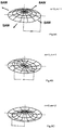
- FIGS. 7A-7C are illustrations of piezo-electric plates 305 which are vibrating in natural vibration modes.
- Piezo-electric plates 305 may act as actuators 200 in accordance with embodiments of the present invention.
- the vibrations excited in piezo-electric plates 305 may have different n and m, depending on the excitement frequency.
- a distance A between maximum amplitudes corresponds to one-half the wavelength of SAW activated by piezo-electric plate 305.
- This feature enable creation of SAW with varying characteristics such as wavelength and depth. Depth is generally equal to 1-2 wavelengths.
- FIGS 8A-8C are illustrations of piezoelectric disks 306 which are vibrating in symmetric or antisymmetric Lamb vibration modes, or in natural vibration modes.
- the same dependence of n and m corresponds to excitement frequency, as described above with reference to FIGS. 7A-7C .
- SAW of varying different characteristics may be created because the distance A, between maximum amplitudes of excitement vibration corresponds to one-half the wavelength of SAW excited on the skin.
- actuator 200 may have many other configurations, including ring, string, shell-like, strips, etc.
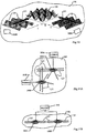
- FIGS. 9A-9C are schematic illustrations of actuator 200 in place in accordance with several embodiments of the present invention.
- the actuators 200 depicted in FIGS. 9A-9C may differ from each other in a mode of spatially-non-uniform and variable elastic deformations, and in an aspect of energy parameters emitted to the skin which is used for therapeutics needs.
- actuator 200 may have a "wedge” or “comb” type of configuration, wherein spherical waves (longitudinal and transverse) are transformed into surface waves.
- actuator 200 includes a base portion 280 and an activating portion 282.
- Base portion 280 comprises protruding elements 251 which are in contact with skin 402.
- each of protruding elements 251 has a triangular equilateral shape, and several of these protruding elements 251 are arranged in a row.
- Voltage is applied to activating portion 282 of actuator 200 via processor 300, which may include, for example, a power supply.
- Voltage from processor 300 excites elastic volumetric (three dimensional) vibrations in activating portion 282, which are transmitted to base portion 280 and to protruding elements 251. This results in production of SAW 121 in two opposite directions along skin 402.
- base portion 280 is comprised of piezoelectric material and in other embodiments, only activating portion 282 is comprised of piezoelectric material. In some embodiments, when base portion 280 is comprised of piezoelectric material, base portion 280 acts as activating portion 282.
- FIG. 9B is an illustration of base portion 280 having protruding portions 251 which are rectangularly shaped.
- This configuration causes a two-directional vibration along one axis.
- the requirement of acoustic synchronization is ensured by means of distances between the grooves, which are equal to ⁇ a.
- the SAW which spreads along the grooves excites a surface wave in skin 402. Modification of the groove slope angle increases or decreases the vibration amplitude.
- protruding portions 251 may have an angled configuration such as a "comb" shape as well, enabling SAW propagation in one direction only.
- FIG. 10 is an illustration of one method for achieving SAW, showing a summation of SAW from two actuators 200A and 200B placed at an angle ⁇ relative to one another on a surface of skin 402.
- running type waves 122 excited and transmitted by each of actuators 200A and 200B interfere with each other, thus forming standing waves 123 on the surface of skin 402.
- the waves' interferences in the areas of overlap concentrate acoustic energy.
- actuators 200A and 200B are connected to one processor 300. In other embodiments, separate processors may be used for each of actuators 200A and 200B.
- FIGS. 11A and 11B are illustrations showing actuators 200A and 200B attached to separate processors 300A and 300B, and to one processor 300, respectively.
- a first actuator 200A is in electrical communication with a first processor 300A
- a second actuator 200B is in electrical communication with a second processor 300B.
- First and second actuators 200A and 200B are placed in different locations on skin 402, and may optionally be repositioned if necessary.
- actuators 200A and 200B are at angles to one another.
- first and second actuators 200A and 200B may in some embodiments be in electrical communication with a single processor 300.
- the relative placement of actuators 200A and 200B remains relatively constant, but the overall positioning may be changed if necessary.
- FIG. 12 is an illustration of another embodiment of the present invention, wherein SAW focused standing waves 123 are created with serial IDT 205 actuators placed in a circular configuration.
- This type of configuration may be useful for IDT 205 actuators, since IDT 205 actuators tend to create weak SAW; thus, it may be advantageous to focus the energy concentration.
- running waves propagating in a direction shown by arrows 211 to the center of the circular configuration
- will interfere with each other in the center thus creating an area of standing waves 123 with much higher acoustic power.
- FIG. 13 is a graphical illustration of pressure from a focused standing wave versus distance from the center for high frequency acoustic waves obtained when actuators are placed circularly, as depicted in FIG. 12 .
- the pressure greatly increases in the central zone due to the focusing effect.
- a focused effect such as the one described above with respect to FIGS. 12 and 13 may also be obtained by using a ring-shaped piezo-element for activating portion 282 of actuator 200.
- Running waves are directed inwardly, towards a center of the ring-shaped piezo-element. Interaction of these running waves with one another causes formation of standing waves at the center.
- the minimal thickness of a ring-shaped piezo-element for this purpose may be in the order of 0.05 mm to 0.1 mm.
- the inner radius of the ring-shaped piezo-element may be in the order of 1-100 mm. Other dimensions are possible as well.
- the ring-shaped piezo-element has an outer layer, which may be, for example, an absorbing material such as rubber, silicone, polymer or metal or any other suitable absorbing material.
- the absorbing material may be adapted to absorb the acoustic vibrations which are directed outwardly from the ring, if it is desired.
- a power supply system may be adapted to supply electric input to the ring-shaped piezo-element. The frequency of the electric input may be selectively controlled. Electric input from the power supply may be delivered to the conductive material of ring-shaped piezo-element, which may then cause substantial vibrations of the ring-shaped piezo-element.
- the electric input delivered to the ring-shaped piezo-element may cause thickness, longitudinal, or torsion or any other acoustic wave form.
- the selected frequency may be dependent upon various system parameters, including, but not limited to the thickness of the piezoceramic material used for ring-shaped piezo-element.
- the frequency applied to a ring-shaped piezo-element having a thickness of 0.05 mm may be approximately 20 MHz and the frequency applied to a ring-shaped piezo-element 220 having a thickness of 50 mm may be approximately 0.1 MHz.
- Other frequencies and thicknesses may be selected.
- the ring-shaped piezo-element is constructed of several arc sections, which may be excited simultaneously or sequentially, or in any other combination, resulting in lower energy assumptions with higher focused results.
- serially positioned ring-shaped piezo-elements may create multiple areas of focused SAW effects.
- FIG. 14A is an illustration of an embodiment of the present invention, showing creation of SAW focused standing waves using a ring-shaped piezo-element 220, as shown in FIG. 14B .
- Ring-shaped piezo-element 220 is placed on skin 402.
- SAW form outwardly and inwardly with respect to ring-shaped piezo-element 220, as depicted by arrows 211.
- This causes a focusing of running waves at a center area resulting in standing SAW in a focused area 225 as depicted in FIG. 14A and 14B , and may create extremely high pressure or temperature at focused area 225.
- Disinfection is not always satisfactory due to skin structure - irregularity of the skin which contains hydrophobic pockets, air bubbles, fissures and crevices which compromise sufficient penetration, and due to quick drying of the disinfectant. It is known in the art that ultrasound is an enhancer of antibiotic action, both by enhancing the bactericidal effect of antibiotics and significantly increasing the transport of the antibiotic across biofilms.
- Acoustic pad 500 may be, for example, a disinfecting patch having the ability to achieve more efficient disinfection before surgical procedures, catheterization and venipuncture.
- Acoustic pad 500 includes an actuator 200 and a processor 300 either separate from or attached to actuator 200.
- acoustic pad 500 is a disposable patch, and may have multiple layers, including, for example: a transparent protective layer, a permeable adhesive layer, a disinfecting agent layer, a layer with PZT actuator, and a protecting cover.
- Acoustic pad 500 Prior to insertion of a medical device into the body, the protective layer is removed from acoustic pad 500, and adhesive layer is placed against the skin 402 at the insertion site of skin 402.
- Acoustic pad 500 is configured to enhance the disinfecting ability of a disinfectant which is contained in the disinfecting layer, such as, for example, chlorohexidine or povidine.
- Acoustic pad 500 may be any suitable size, such as but not limited to, about 10 cm X 10 cm for certain applications.
- Actuator 200 causes SAW of Rayleigh, "pseudo" Rayleigh or Lamb type , matched as 121 to be created on the skin.
- SAW 121 can mechanically enhance the penetration and distribution of disinfectants evenly and thoroughly, and acoustic pad 500 maintains a moist environment for bacteria to enter the intravenous catheter insertion site.
- Acoustic pad 500 is reversibly attached to the skin 402, and may remain on the skin 402 for at least a week, although disinfectation may take place in as little as 2 to 5 minutes.
- acoustic pad 500 is pre-cut, and may be positioned on skin 402 after skin 402 is already in place, thus protecting the already formed insertion wound from bacteria contamination.
- acoustic pad 500 may be used to enhance the preparation of the skin for venipuncture or catheter insertion sites prior to catheterization and for post insertion hygiene maintenance; disinfection of lacerated wounds, necrotic wounds and burns; and wound healing.
- acoustic pad 500 may be used as a hydrophilic wound dressing to absorb exudates and cover the wound caused by the use of vascular and other medical devices (IV catheters, CVL, arterial catheters, dialysis catheters drains, externally placed orthopedic pins). It is also intended to reduce local infections, catheter related blood stream infections, and skin colonization of microorganisms.
- the energy levels may be controlled by medical professionals.
- Activation of SAW by actuator 200 causes micro streaming of an active agent placed on the wound, resulting in better distribution of the agent on the surface.
- multiple actuators 200 may be used. If two actuators are applied at the angle to each other, running waves in each direction will result in standing waves in the cross region. These standing waves induce disinfectant penetration into the skin's deeper layers.
- SAW actuators 200 may be used in combination with existing, commonly used patches such as, for example, Biopatch TM .
- the use of a patch such as acoustic pad 500 may reduce the necessity to replace peripheral catheters every two days, as is the current practice.
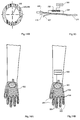
- FIGS. 16A and 16B are illustrations of an acoustic glove 502 in accordance with embodiments of the present invention.
- Acoustic glove 502 may have an outer layer and an inner layer, and may be comprised of gauze, cotton, wool, polyester, rayon or any other natural or synthetic material on the outer layer, and latex or any other non-latex plastic or polymer on the inner layer.
- the outer layer of acoustic glove 502 is pre-treated with a disinfectant such as dacron, chlorhexidine gluconate, alcohol, iodine or any similar disinfectant or any combination thereof.
- a packaging shield protects the disinfecting liquid from vaporizing. The packaging shield may be opened at the time of the disinfecting procedure.
- Acoustic glove 502 may include a sleeve portion of any suitable length for placing on an arm, or may not have a sleeve portion at all. Upon activation of SAW via actuators 200, acoustic glove 502 is effective against bacteria, virus and picons, as well against vancomycin resistant enterococci (VRE) and methacillin resistant staphylococci aurieus. Acoustic glove 502 can enhance a pre-operative disinfecting procedure.
- VRE vancomycin resistant enterococci
- Stylococci aurieus methacillin resistant staphylococci aurieus.
- Acoustic glove 502 can enhance a pre-operative disinfecting procedure.
- finger portions 504 are partially or completely comprised of latex, and a central portion is comprised of gauze, cloth, cotton, wool, polyester, rayon or any other natural or synthetic material.
- the central portion may be pre-treated with chlorhexidene gluconate, alcohol, iodine or any similar disinfectant.
- portions of acoustic glove 502 are fitted with actuators 200, which are connected to a processor 300.
- processor 300 is a battery-powered system.
- Portions which have actuators 200 thereon may include, for example, latex portions of acoustic glove 502, and may be confined to finger portions 504 or may be placed on a central portion of acoustic glove 502. Mechanical vibrations activated by actuators 200 enable deeper penetration of the disinfecting liquid to the skin layers, providing better results.
- Wound healing undergoes several phases, which are known to be affected by ultrasound.
- the first phase is the inflammatory phase, wherein ultrasound causes a degranulation of mast cells resulting in the release of histamine. Histamine and other chemical mediators released from the mast cells are thought to play a role in attracting neutrophils and monocytes to the injured site. These and other events appear to accelerate the acute inflammatory phase and promote healing.
- the second phase is the proliferative phase. Ultrasound has been noted to affect fibroblasts and stimulate them to secrete collagen. This can accelerate the process of wound contraction and increase tensile strength of the healing tissue. Connective tissue will elongate better if both heat and stretch are combined. Continuous ultrasound at higher therapeutic intensities provides an effective means of heating of deeper tissue prior to stretch.
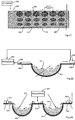
- FIG. 17 is a schematic illustration of the use of an actuator 200 for SAW propagation on the surface of a wound 404, wherein actuator 200 is placed nearby at the site of healthy skin 402. Since SAW have an ability to travel between two media, they may be distributed at a wound surface without direct contact.
- FIG. 18 is an illustration of distribution of SAW between an inner surface of wound 404 and skin 402. Frequencies may be in a range of 0.1 Hz - 10 MHz.
- SAW may be distributed in both areas either simultaneously or non-simultaneously.
- wound 404 is treated with an active pharmaceutical agent (drug, gel, etc).
- SAW may be distributed between the active pharmaceutical agent and air, between the active pharmaceutical agent and the wound, and between the wound and the underlying skin. Any and all of these combinations are possible.
- SAW may be created on the skin surrounding the wound. SAW actuator creates simultaneous wave distribution on the wound surface and in along external/internal wound perimeter. All of the methods disclosed herein may be applied to external or internal wounds.
- FIG. 19 is an illustration of an actuator 200 for producing SAW in combination with a wound dressing 408.
- Wound dressing 408 is placed over pharmaceutical agent 406.
- SAW are produced at the interface between wound dressing 408 and pharmaceutical agent 406.
- Frequencies may be in a range of 1 KHz-20MHz.
- FIG. 20 is an illustration of SAW activation for treatment of multiple wounds 404.
- two or more wounds 404 may be treated simultaneously or sequentially using one actuator 200.
- Actuator 200 is placed on a portion of healthy skin 402 which lies between two wounds 404.
- Actuator 200 is configured to propagate SAW in multiple directions, allowing treatment of both wounds 404 which are on opposite sides of actuator 200. This spreading of waves in multiple directions occurs automatically with the use of actuator 200.
- FIG. 21 is a schematic illustration of SAW activity, including depth, intensity and direction.
- SAW surface acoustic waves penetrate to the depths up to two wave lengths
- the penetration depths may be controlled through wave length, which depends on frequency.
- FIG. 21 when SAW has a relatively long wavelength, deep penetration is achieved, in comparison to SAW with short wavelengths. Particles vibrate elliptically, as indicated by ellipses 506, and the energy intensity decreases with increased distance from the surface. This is depicted schematically in FIG. 21 by showing increasingly smaller ellipses as the distance from the skin 402 surface increases.
- the intensity is controlled by the voltage applied by processor 300, and the wavelength is controlled by the frequency applied.
- SAW actuators 200 may work in a range of between 10 Hz-10 MHz in continuous and pulse regimes. These features enable management of the depth of SAW distribution in a discrete or continuous manner, depending on the requirements. When SAW are activated with a short wavelength by stimulating with low frequencies, a thin layer of depth penetration is achieved.
- FIG. 22 is a schematic illustration of wound healing using an actuator 200 and a sensor 232.
- actuator 200 is placed on healthy skin 402 on one side of wound 404
- sensor 232 is placed on healthy skin 402 on an opposite side of wound 404.
- Both actuator 200 and sensor 232 are in electrical communication with processor 300.
- acoustic sensor 232 is based on differences in acoustic wave velocity in healthy versus wounded skin and may include a miniature photo device and may include web-based and telemedicine means.
- Processor 300 may control the amount of SAW in real-time by comparing the measured parameters with desired parameters, thus creating a feedback loop. Similarly, as shown in FIG.
- treatment and sensing of multiple wounds is possible, by, for example, placing actuator 200 between wounds 404 and sensors 232 on opposite sides of wounds 404. Both sensors 232 and actuator 200 are in electrical communication with processor 300 and may optionally provide a continuous feedback system, as described above with reference to FIG. 22 .
- the principle of the sensor action is based on different surface acoustic wave SAW velocities in the wound structure, healthy skin and healing wound.
- the sensor achieves an electrical signal in response to SAW direct piezoelectric effect, and thus can measure wave propagation velocity, which differs in healthy versus wounded skin.
- it is possible to estimate the efficiency of wound treatment by measuring the velocities of SAW transmission using an acoustic skin analyzer. It has been found that during the first phase of wound healing, SAW have velocities of 50-90 m/s, in the second phase the velocities decrease to 35-49 m/s and during the third phase, velocities decrease yet further to 25-35 m/s. SAW velocities in healthy skin were found to be 18-25 m/s. These measurements correlate with cytological and histological findings.
- multiple actuators may be used in combination to treat one area.
- a first actuator may be placed in the nearby region (approximately 0.5-2 cm distance from the wound) and a second actuator may be placed in a more distant region (approximately 2 m).
- the first actuator acts in a "Fresnel” regime, wherein a more focused beam is achieved, and the second actuator acts in a "Fraunhofer” regime, wherein a beam of an extended area is achieved.
- An interaction between the waves of the first and second actuators results in a standing wave at the cross area of the two beams.
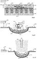
- FIGS. 24-28 are schematic illustrations of a method of micro-streaming using SAW.
- a micro-streaming effect is created due to the running waves achieved in the SAW process and elliptical oscillations of the surface particles.
- the result of these two characteristics is liquid micro-streaming, wherein a direction of micro-streaming is opposite to the direction of SAW propagation, because the elliptical motion of surface particles causes the contacting liquid particles to move in an opposite direction.
- FIG. 24 is a schematic illustration showing opposite directions of SAW propagation and liquid microstreaming.
- a liquid 414 covers a body tissue 400.
- Actuator 200 and processor 300 are placed on a portion of the surface of body tissue 400.
- SAW Upon activation, SAW are created in a SAW propagation direction, as shown by arrow 410. Due to the elliptical motion of particles, as shown schematically by ellipses 506, liquid 414 begins to move in an opposite direction, as shown by arrow 412. Micro-streaming may aid in wound healing.
- the velocity of the liquid during micro-streaming may be in a range of 1-50 microns/min, depending on the dynamic parameters of the liquid and the intensity of SAW.
- FIG. 25 is a schematic illustration showing the influence of SAW on bacteria 416 due to micro-streaming.
- Micro-streaming will result in inhibition of bacteria from docking and adhering to the surface, and further results in streaming of bacteria within the liquid out of the wound site in a direction opposite to SAW propagation as shown by arrows 410 and 412. This process is similar to micro-pumping, but without the need for vacuum. Methods for micro-streaming may be applied with or without a wound dressing.
- FIG. 26 is a schematic illustration showing the influence of SAW on drying, in accordance with additional embodiments of the present invention.
- SAW produce micro-vibrations in the liquid molecules, which thus obtain kinetic energy and vaporize more easily.
- SAW can enhance a drying effect, wherein vaporization occurs away from the wound site, as shown by arrow 422.
- FIG. 27 is a schematic illustration showing SAW applied to wound healing, with the addition of a conventional ultrasound transducer 508.
- conventional ultrasonic waves of sufficient intensity such as in a range of about 0.5-10 W/cm 2
- the liquid may work as a nebulizer to produce a very fine fog or mist.
- Aerosol mists produced by ultrasound are preferred as compared to drugs in a liquid or moisture state because a smaller particle size can be obtained.
- the application of two techniques together can enhance wound healing.
- the methods described herein topically transmits acoustic energy to a medicine on the wound surface (such as antibiotics, for example) without the need to contact an infected, inflamed or painful tissue with an instrument.
- a significant debridement, cleansing and bactericidal effect can occur when SAW of Rayleigh or "pseudo" Rayleigh or Lamb type reach and are distributed on a wound surface using the method of the present invention.
- use of the methods described permits a significant reduction in volume of liquid medicines used as compared with traditional methods for wound treatment and allows for precise dosage of the acoustic energy, rate and duration as per physician decision.
- the methods described decrease healing times for inflammatory and purulent infected wounds, up to 1.5 to 2 times faster than traditional methods. This effect results from a bactericidal, blood flow increasing and mechanical cleansing effect of the activated drug particles, which obtain energy due to the acoustic waves. All of these advantages may be further enhanced by the use of conventional ultrasound.
- Specific advantages of the combination of ultrasound and SAW include the following: energized and highly activated antibiotics, drug penetration into the tissue surface up to 0.5 mm in depth, more efficient destruction of the surface bacteria, etc.
- the SAW of the present method also stimulates healthy cell growth to aid in granulation and epitheliation of the healing tissue.
- the method described offers an approach that may re-establish use of some traditional antibiotics and establish a method for fighting bacteria without antibiotics.
- the effect of the method described in highly activating antibiotics may allow some traditional antibiotics to overcome bacteria which have become resistant to that antibiotic.
- the low frequency SAW applied in the method of the present invention physically inhibit biofilm formation.
- the combination of the highly activated antibiotics and of the SAW in the method described produce a strong bactericidal effect not found in regular topically applied or orally ingested antibiotics. This combined effect may significantly increase the healing of purulent infected wounds.
- the SAW and/or combined SAW/conventional ultrasound may be further enhanced by the addition of a laser beam.
- the conventional ultrasound is continuous and in other embodiments the conventional ultrasound is pulsed.
- the laser therapy may include a pulsed, scanned or gated laser continuous wave laser or incoherent radiation of ultraviolet therapy.
- the combination of SAW, conventional ultrasonic waves, laser beams and energized medicines should destroy the surface bacteria and result in a higher level of disinfection by the energized liquids as compared to ordinarily applied liquids.
- the SAW process and conventional ultrasound and laser energy also stimulates healthy cell growth to aid in granulation and epithelation of healing tissue.
- Embodiments of the present invention relate to systems for wound treatment using a SAW process combined with different energy sources, such as a laser, conventional ultrasound, electric current, magnetic field, ultraviolet, microwaves, radio frequency, light-emitting diodes (LEDs) and or equivalent sources, as will be apparent to one skilled in this art.
- energy sources such as a laser, conventional ultrasound, electric current, magnetic field, ultraviolet, microwaves, radio frequency, light-emitting diodes (LEDs) and or equivalent sources, as will be apparent to one skilled in this art.
- Post-operative adhesions are a common surgical complication. Adhesions are particularly troublesome in a variety of locations, e.g., between the pericardium and sternum following open heart surgery, in the abdominal cavity following bowel procedures and, especially, in the retroperitoneal space involved with gynecological reconstruction.
- Two primary approaches have been explored. The first involves implantable barrier films prepared, for example, from hyaluronic acid or hydrogonic acid or oxidized cellulose, but this approach has not met with success because the location of where to place the film to prevent adhesions is not easily determined.
- the second approach involves the instillation of a bolus of solution, e.g., N,O-acetylchitosan, to wet the general area where adhesions might be expected.
- a bolus of solution e.g., N,O-acetylchitosan
- these adhesions usually form during the first post-operative week. Therefore, the task is to prevent fibroblasts (which produce the collagenous adhesions) from adhering to local tissue surfaces during the first week.
- a non-adhesive butterfly bandage comprising small SAW actuators could be a solution to this need.
- Such devices can also optionally comprise drugs or the like to be released transdermally.
- Such devices may optionally be used with decabitous ulcers, in venostatis situations (in diabetic patients, pressure on the skin and bone causes erosion and ulcer).
- such a wound dressing device can be coupled with a moiety, such that the moiety can enhance wound healing (e.g., cell growth).
- the anti-adhesion solutions of the current invention are expected to prevent cellular attachment.
- the anti-adhesion embodiments herein are optionally in various forms (e.g., liquid application forms, film application forms, etc.).
- Dressings (hydroactive and conventional gauzes) for surgery can be used with the addition of SAW actuators for prevention of adhesion.
- Some embodiments can optionally be a mesh (e.g., synthetic, metal, fabric) coating with the addition of SAW actuators, wherein the combined coating is laid directly over the wound cavity.
- bacteriostatic dressings and/or bactericidal dressings may be used.
- silver and/or zinc and/or titanium oxides which have bactericidal characteristics, may be used with SAW actuators to further increase their efficacy.
- SAW actuators may be incorporated into the dressings or may be placed at their peripheries.
- Closure of an open wound requires inward migration of surrounding epithelial and subcutaneous tissue. Some wounds, however, are too large and are unable to heal spontaneously. In such instances, a zone of stasis in which localized edema restricts the flow of blood to the epithelial and subcutaneous tissue forms near the surface of the wound. Without sufficient blood flow, the wound is unable to successfully fight bacterial infection and is accordingly unable to close spontaneously.
- An initial stage of wound healing is characterized by the formation of granulation tissue which is a matrix of collagen, fibronectin, and hyaluronic acid carrying macrophages, fibroblasts, and neovasculature that forms the basis for subsequent epithelialization of the wound. Infection and poor vascularization hinder the formation of granulation tissue within wounded tissue. It is therefore desirable to provide a technique for increasing blood circulation within wounded tissue to promote spontaneous healing and to reduce infection.
- Sutures are often used to apply force to adjacent viable tissue in order to induce the edges of a wound to migrate together and heal.
- sutures apply a closure force to only a very small percentage of the area surrounding a wound.
- the tension produced by the sutures can become great causing excessive pressure to be exerted by the sutures upon the tissue adjacent to each suture.
- the adjacent tissue often becomes ischemic thereby rendering suturing of large wounds counterproductive.
- the size or type of a particular wound may prevent the use of sutures to promote wound closure.
- partial thickness burns Other types of wounds in which ischemia leads to progressive deterioration include partial thickness burns.
- a partial thickness burn is a burn in which the cell death due to thermal trauma does not extend below the deepest epidermal structures such as hair follicles, sweat glands, or sebaceous glands.
- the progression of partial thickness burns to deeper burns is a major problem in burn therapy.
- the ability to control or diminish the depth of burns greatly enhances the prognosis for burn patients and decreases morbidity resulting from bums.
- Partial thickness burns are formed of a zone of coagulation, which encompasses tissue killed by thermal injury, and a zone of stasis.
- the zone of stasis is a layer of tissue immediately beneath the zone of coagulation.
- a method of SAW-induced micro-pumping can promote tissue migration and facilitate closure of the wound. By creating the SAW induced micro pumping, a negative pressure is formed, which facilitates wound closure. This method may be applicable to wounds, burns, infected wounds, and live tissue attachments.
- a wound treatment method involves a fluid impermeable wound cover which is sealed over a wound site. A screen in the form of an open-cell foam screen or a rigid porous screen is placed beneath the wound cover over the wound. SAW micro pumping action supplies suction within the wound cover over the treatment site.
- SAW propagation in the interface wound-dressing material results in non-sticking of the dressing material.
- the dressing material serves as an acoustic transmission line and acoustic energy is distributed - even to relatively distant locations.
- SAW can be used to prevent and treat pressure sores (in a bandage or patch configuration as well in a sock and partial sock configuration), for treatment of burns, for removal of wound dressings in a non-stick fashion and for diabetic wound preventing.
- a wound treatment method may be based on the same SAW distributing methods as described above and may provide wound treatment by applying micro pumping to the wound in a controlled manner for a selected time period.
- the application of micro pumping to a wound provides such benefits as faster healing, increased formation of granulation tissue, closure of chronic open wounds, reduction of bacterial density within wounds, inhibition of burn penetration, and enhancement of flap and graft attachment.
- Wounds that have exhibited positive response to treatment by the application of micro pumping include infected open wounds, decubitus ulcers, dehisced incisions, partial thickness burns, and various lesions to which flaps or grafts have been attached.
- FIG. 28 is an illustration of multiple actuators 200 placed near wound 404, and propagating SAW towards wound 404 as represented by arrows 211, which results in micro-streaming of the wound liquid 414 in an opposite direction - out of the wound 404, as represented by arrows 412.
- each of the two actuators 200 may operate on a different frequency, which allows for SAW to be created at different depths. These actuators may move the wound biomass in an opposite direction with respect to the direction of SAW propagation. Furthermore, SAW may influence wound healing by providing better distribution of the drugs or healing creams on the surface of the wound and micro-streaming of the wound bio mass out of the wound area.
- FIG. 29 is a schematic illustration of an acoustic pad 500 for inducing micro-pumping, in accordance with embodiments of the present invention.
- Acoustic pad 500 includes a patch 501, wherein the patch 501 has several components either attached thereto on its surface, or sewn into its layers.
- the components include at least one actuator 200, processor 300, a battery 510, and optionally a sensor 232.
- a wound dressing is spread onto the surface of patch 501.
- a direction of SAW propagation is shown by arrows 211.
- micro-pumping may occur in a central part of the wound due to standing waves. Furthermore, this micro-pumping may induce negative pressure, which can aid in wound healing.
- acoustic pad 500 includes thin capillaries, or suction tubes, through which the wound dressing can directly contact the wound area.
- the actuators 200 create SAW on the capillaries, wherein the direction of SAW is opposite to the wound liquid movement direction, which due to negative pressure creates suction within the capillaries, causing micro-pumping occur. This obviates the need for vacuum and thus also for sealing of the wound dressing (in order to create the vacuum).
- acoustic pad 500 is a disposable patch.
- damaged tissue may be treated by applying micro-pumping to a wound over an area sufficient to promote the migration of epithelial and subcutaneous tissue toward the wound and for a time period sufficient to facilitate closure of the wound.
- the active disposable patch is useful for treating pressure sores and preventing diabetic wounds.
- the described methods are also suitable for treating a burn wound by applying a negative or reduced pressure to the burn over the surface and for a time sufficient to inhibit progression in the depth of the burn.
- the method is useful on a partial thickness burn soon after its infliction.
- One use of this method is its application to a wound for a selected time period such as at least three days to reduce the bacterial density of an infected wound to the point at which surgical closure can be attempted.
- Another aspect is a method of enhancing the attachment of adjacent tissue to a wound which comprises applying micro-pumping to a joined complex of the adjacent living tissue and the wound at a sufficient magnitude of micro pumping and for a sufficient time duration to promote the migration of epithelial and subcutaneous tissue toward the complex. This method enhances attachment of adjacent tissue to tissues of the wound edges.
- Another use of this method is to enhance attachment of an open skin graft to the wound tissue.
- FIG. 30 is a schematic illustration of a system for producing SAW having gauze or other dressing material coupler 512 for wound biomass coupling.
- SAW are transmitted through coupler 512, and the wound mass is soaked due to the micro-pumping effect.
- the wound biomass is configured to move in a direction, shown by arrows 423 which is opposite to the direction of SAW, shown by arrows 211.
- two actuators 200 may be used.
- each of two actuators 200 may have different intensities and/or frequencies, contributing to a filtration effect, when bio mass particles of different sizes are sucked into opposite directions.
- the active capillaries may create wound mass suction in a direction depicted by arrows 423 which is opposite to a direction of SAW propagation, depicted by arrow 211.
- SAW decrease the Reinold's number of the liquid; therefore the liquid near the capillary walls moves more with respect to the wall of the capillary, preventing bacterial adhesion to the capillary walls.
- some capillaries are used for wound mass removal, while other capillaries are simultaneously or non-simultaneously used for delivery of liquid drugs.
- FIG. 32 is an illustration of an active acoustic pad 500, in accordance with embodiments of the present invention.
- multiple actuators 200 are arranged in a star-like configuration, with processor 300 positioned in the center.
- This configuration enables circular propagation of SAW, as depicted by arrows 410.
- an actuator 200 may be placed at the center.
- This configuration enables SAW propagation of running waves from the center to the periphery.
- the character of the wave propagation may be chosen by a medical professional depending on the phase or condition of wound healing. For example, in the first phase of wound healing it may be desirable to use the configuration described with respect to FIG.
- capillaries 418 may be positioned on two opposing sides of acoustic pad 500, while in other embodiments, capillaries 418 may be positioned around acoustic pad 500. Any suitable configuration of actuators 200 and/or capillaries 418 is possible.
- FIG. 33 is an illustration of a wound healing tape 420, in accordance with embodiments of the present invention.
- Actuators 200 are incorporated into a layer of wound healing tape 420.
- incorporated actuators are IDTs 205.
- actuators 200 and sensors 232 are incorporated into acoustic pad 500, both of which are connected to processor 300.
- Processor 300 may transmit data received from sensors 232 in real time to a computer or a telemedicine system and a medical professional may manage the healing process and regulate healing intensity through commands to processor 300.
- MRSA Methicillin-resistant Staphylococcus aureus
- RSA Oxacillin-resistant Staphylococcus aureus
- MRSA colonization in an otherwise healthy individual is not usually a serious matter, infection with the organism can be life-threatening to patients with deep wounds, intravenous catheters or other foreign-body instrumentation, or as a secondary infection in patients with compromised immune systems. This is partly due to the fact that MRSA does not respond to the antibiotics normally prescribed for the infections in question, and can hence progress unchecked.
- Vancomycin and teicoplanin are glycopeptide antibiotics used to treat MRSA infections. These drugs are administered intravenously.
- Several new strains of the bacterium have been found showing antibiotic resistance even to vancomycin and teicoplanin; those new evolutions of the MRSA bacteria are dubbed "vancomycin intermediate-resistant Staphylococcus aureus” (VISA).
- VSA vancomycin intermediate-resistant Staphylococcus aureus
- Linezolid, quinupristin/dalfopristin, daptomycin, tigecycline are more recent additions to the therapeutic arsenal, generally reserved for severe infections which do not respond to glycopeptides.
- cystic fibrosis patients are often treated with multiple antibiotics in hospital settings, they are often colonized with MRSA, potentially increasing the rate of life-threatening MRSA pneumonia in this group.
- the risk of cross-colonization has led to increased use of isolation protocols among these patients.
- CAMRSA apparently represents a hybrid between MRSA which escaped from the hospital environment and the once easily treatable community organisms. Most of the hybrid strains also acquired a virulence factor which makes their infections invade more aggressively, resulting in deep tissue infections following minor scrapes and cuts, and many cases of fatal pneumonia as well.
- the present invention includes treatment of MSRA using SAW.
- SAW is used to fight bacterial infections, and enhance antibiotic efficacy, as well as enhance wound healing and drug delivery.
- the skin is a multi-layered organ.
- the stratum corneum (SC) the outermost layer of the skin - presents the principal resistance to the penetration of topically applied compounds, such that the number of molecules currently used in topical and cosmetic dermal delivery is quite limited.
- Mild treatment of the skin by ultrasound is a commonly practiced method used by cosmeticians for cosmetic skincare. It is a purpose of the present invention to reduce the appearance of fine lines and wrinkles and/or rapidly lighten photodamaged skin by applying moisture and/or other cosmetic ingredients to the stratum corneum.
- SAW actuated devices and disposable patches can address a host of cosmetic and topical concerns, including moisturizing, firming, anti-cellulite, acne, facial redness, sun damage repair.
- the use of SAW can enhance the permeation of compounds, due to elliptical motion of particles during micro vibration on the surface, and due to micro-streaming resulting therefrom.
- micro-electronic skin care products provide a significant increase in the percentage of active cosmetic ingredients that can be delivered onto the upper layers of the skin.
- Skin aging includes a slower turnover of the surface skin and slower wound healing. Thinning makes the skin more fragile and vulnerable to damage and more sensitive to irritating environmental factors and allergens. Collagen cross-linking is damaged and as a result, the skin loses much of its strength and elasticity. The moisture holding capacity is decreased and the skin becomes dry and loose. The fat content in the skin is decreased, resulting in a less plump and smoother look. The number of blood vessels in the skin decreases, and the skin loses its youthful color and glow.
- Anti-aging formulations include anti-wrinkle, de-pigmentation, skin regeneration, and sunspot treatment, among others.
- Skin aging results in a slower turnover of the surface skin and slower wound healing.
- the skin becomes more fragile and vulnerable to damage and more sensitive to irritating environmental factors and allergens.
- the moisture holding capacity is decreased, the skin becomes dry and loose, losing its youthful color and glow.
- Embodiments include a SAW-based electrically driven method to more effectively reduce the appearance of fine lines and wrinkles, leaving the skin feeling silky and smooth for several hours. These methods may further erase signs of fatigue, reduce the appearance of fine lines and wrinkles, diminish the appearance of crow's feet, smooth out and lift skin around the eye contour, deliver extra moisture to the skin, and improve firmness of the eye contour.
- Activated SAW anti-aging skincare devices may be produced as a hand-held device and/or as disposable patches, as well as in a variety of shapes for different application areas.
- Hyper-pigmentation and melasma are common skin disorders, predominantly affecting the faces of women. It appears as symmetrical hyper-pigmented maculae, which can be confluent or punctuate. The cheeks, upper lip, chin, and forehead are the most common locations, but it can occasionally occur in other sun-exposed locations. The treatment of hyper-pigmented skin is still quite unsatisfactory, as indicated in cosmetic scientific literature. Thus, there is a clear need to develop new, safe skin lightening systems, which will provide desirable alleviation of hyper-pigmentation.
- SAW activated devices and patches can enhance delivery of a wide variety of skin and spot whitening molecules, thus enhancing the power of common skin whitening cosmetic ingredients, the decrease of hyper-pigmentation skin discoloration, sun, and age spots significantly faster than ordinary cosmetic creams alone.
- Flexible patch 514 includes SAW actuators 200, with a processor 300 and at least one battery 510 incorporated therein, and may be attached to the facial skin 402.
- the depth of SAW propagation may be managed by varying the wave frequency.
- Battery 510 is configured to provide energy in the range of 5-20 mW / cm 2
- processor 300 may be configured to control one or more actuators 200 simultaneously.
- Processor 300 may act in accordance with a predetermined program, and may control simultaneously one or more patches.
- actuator 200 distributes the waves continuously as shown by arrows 211 and ellipses 506.
- actuator 200 distributes SAW in one direction, and SAW may be absorbed and reflected due to energy absorbers such as gauze, synthetic porous materials, gum, and the like, which can prevent them from being propagated in other directions.
- flexible patch 514 includes multiple actuators, controllers and batteries, each of which is a system which can operate independently. Propagation of running SAW in several directions can result in standing waves in an overlapping area. This may provide a more focused acoustic energy treatment.
- actuator 200 is ring-shaped, or multiple actuators 200 may be circularly arranged.
- This configuration allows for standing waves to be created in the center portion, thus concentrating acoustic pressure and creating a micro-cavitation effect.
- the cavitation creates momentum temperature increasing to about 70°C.
- the described ring or circular actuator construction may be applied for acne healing, or for any other condition wherein high energy may be useful.
- FIG. 35 is an illustration of flexible patch 514, in accordance with embodiments of the present invention.
- Flexible patch 514 is relatively large (in a range of about 1-50 cm 2 ), while actuator 200 is relatively small (in a range of about 0.5-3 cm 2 ).
- Flexible patch 514 further includes an absorbing material 516 at its edges, which can reflect waves.
- a chaotic SAW effect may be achieved on the area treated by flexible patch 514.
- the chaotic directions of SAW are illustration by arrows 410.
- sensors 232 may be incorporated into flexible patch 514 or be placed nearby. Sensors may measure parameters such as skin parameters, velocity of the acoustic wave in the skin, elasticity of skin, temperature, humidity, etc. SAW may provide micro-massage which may be a preventive action for anti aging.
- flexible patch 514 includes multiple actuators 200.
- An active cosmetic agent such as a cream
- SAW are propagated into the cosmetic agent, activating chemical components and causing specific distributions of the cosmetic agent. The process may be managed due to feedback obtain from sensors 232.
- flexible patch 514 also includes a biologically active component, either in liquid or cream form, or as a slow-release component of patch 514. Micro streaming and micro pumping due to SAW may result in increased activity of these active components on skin, thus reducing healing time increasing efficacy.
- Other possible constructions of patches may be produced similar to the ones described above with respect to wound healing.
- FIG. 36 is an illustration of flexible patch 514, in accordance with embodiments of the present invention.
- an arch-like configuration may include a first side and a second side.
- An actuator 200 is included on each side, with a sensor 232 positioned in the middle.
- a battery 510 or multiple batteries are incorporated as well.
- a thin flexible battery such as those available from Power Paper, Nec or Solicore companies may be used.
- Flexible patch 514 includes an adhesive layer, with a protective layer which can be removed prior to adhesion.
- a switch may be included on the protective layer, wherein by removing the protective layer, the battery of the patch is activated.
- FIGS. 37A-37D are illustrations showing various shapes and configurations of patch 514.
- Flexible patch 514 may be elongated, as shown in FIG. 37A , circular, as shown in FIG. 37B , configured to fit on the cheek portions of the face, as depicted in FIG. 37C , configured in an eye-mask configuration, as shown in FIG. 37D , or in any other shape or configuration.
- Patch 514 may be applied to one or both facial sides and may have long action time, for example overnight, or may have short action times, on the order of minutes.
- FIG. 38 is an illustration of a hand-held cosmetic device 518, in accordance with embodiments of the present invention.
- An actuator 200 comprised of a thin piezo-electric plate is placed at a contact portion 530 of cosmetic device 518.
- Contact portion 530 is a portion which is placed against the facial skin during treatment.
- Actuator 200 is comprised of a metallic layer and a piezoelectric layer with an electrode thereon. Metallic layer is positioned outward, such that contact with the skin will be made via metallic layer.
- a processor 300 and a battery 510 are placed within a handle 532 of cosmetic device 518.
- Actuator is electrically connected to processor 300 and battery 510.
- Actuator 200 may have a dual-function mode: micro massaging action under the attachment surface and running surface acoustic waves excitement spread around the actuator, for example, as shown by arrows 211.
- cosmetic device 518 The following are the parameters of cosmetic device 518:
- actuator 200 is all incorporated within a cover 522.
- Actuator 200 causes SAW on the cover surface and on the tube surfaces, as shown by arrows 211.
- the activated surfaces may be attached to the desired surface, for example to the face. Therefore facial micro massage or deeper cream penetration may be achieved.
- actuator 200 with processor 300 and battery 510 are completely incorporated into cover 522.
- actuator 200 is a ring-shaped actuator and covers a portion of cover 522, creating focused waves in the center.
- actuator 200 may be positioned such that acoustic power causes more effective cream to be pushed out of tube 520.
- one or more actuators 200 may be incorporated into cleaning sticks, which may be used as a cosmetic accessory.
- Pain treatment post operative, women after 65, women menstrual pain, sportsmen
- Pain relief patches 524 include a base material and an adhesive layer, with one or more thin plate type piezo-electric actuators incorporated into the base material.
- a separate processor 300 may be provided, wherein processor 300 is in electrical communication with actuators 200.
- the piezo-element actuator may be a piezo bender, and may consist of thin piezo material layer glued to a thin metallic plate.
- the piezo-element is incorporated into the patch base material in such a manner that the metallic plate faces outward with respect to the skin, and the piezo material plus the adhesive layer of the patch face inward with respect to the skin.
- actuators 200 When activated by processor 300, actuators 200 create standing wave on the metallic surfaces. These standing waves penetrate into the depths of the skin layers, resulting in pain relief effect due to enhanced diathermy effect.
- the standing wave is a generator of SAW on the areas surrounding the actuator surfaces, which enhance biological processes (blood flow, liquid and gas exchange, and etc.) further resulting in pain relief.
- the pain relief patch 524 may include a drug layer component (liquid, cream or slow release component of the patch). Micro streaming and micro pumping due to SAW may result in increased activity of these active components, thus decreasing pain relief time and increasing efficacy. Other possible constructions may have a processor 300 in chip configuration, thus allowing it to be incorporated into the patch. Pain relief patch 524 may be a disposable device, or in a pad configuration for repeatable use. A hand-held device for pain relief may have the same components incorporated in a plastic hand held device, and may have one or more acoustic intensity levels.
- ultrasound to targeted drug delivery through a process called sonophoresis.
- This technique uses sound waves instead of needles to inject drugs such as insulin and interferon directly through the skin.
- the high-frequency waves open tiny holes in cell membranes, which make the cells temporarily permeable in localized areas and allow for better penetration of the drug into the blood vessels below the skin.
- This enhances drug effectiveness, reduces dosage requirements and toxicity, and allows clinicians to deliver drugs to specific areas in the body for localized treatment.
- the mechanisms by which ultrasound augments these effects are only partially understood. It is known that ultrasound causes biophysical reactions producing hydroxyl radicals, combinations of hydrogen and oxygen atoms that in turn affect cell membranes. Furthermore, there have been some investigations on the use of low-level ultrasound to enhance the effects of chemotherapy on localized tumors.
- SAW waves provide more efficient pain relief in women, elderly people and sportsmen in comparison to conventionally used physiotherapy (such as ultrasound combined with paraffin bath), when the pain source is near the skin surface.
- conventionally used physiotherapy such as ultrasound combined with paraffin bath
- Achilles pain, hand osteoporosis, and menstrual pain were tested proving pain relief in all these cases resulting in SAW applicators use.
Landscapes
- Health & Medical Sciences (AREA)
- Epidemiology (AREA)
- Life Sciences & Earth Sciences (AREA)
- Animal Behavior & Ethology (AREA)
- General Health & Medical Sciences (AREA)
- Public Health (AREA)
- Veterinary Medicine (AREA)
- Pain & Pain Management (AREA)
- Physical Education & Sports Medicine (AREA)
- Rehabilitation Therapy (AREA)
- Surgical Instruments (AREA)
- Percussion Or Vibration Massage (AREA)
- Prostheses (AREA)
Claims (14)
- Dispositif pour le traitement de la peau, le dispositif comprenant :une partie en contact avec la peau ;un actionneur (200) incorporé dans ladite partie en contact avec la peau, ledit actionneur permettant de produire des ondes acoustiques de surface sur la peau ;un processeur (300) permettant de commander ledit actionneur ; etun capteur incorporé dans ladite partie en contact avec la peau, dans lequel le processeur est configuré pour ajuster des paramètres de sortie sur base d'une rétroaction du capteur ;caractérisé en ce que ledit actionneur est un actionneur de type flexion qui vibre dans un ou plusieurs modes de vibration naturelle de flexion pour produire des ondes acoustiques de surface sur la peau autour de l'actionneur, dans lequel les ondes acoustiques de surface sont produites lorsque la distance entre deux amplitudes maximales de modes de vibration de flexion est proportionnelle à la moitié de la longueur d'onde des ondes acoustiques de surface.
- Dispositif selon la revendication 1, dans lequel ladite partie en contact avec la peau est un timbre.
- Dispositif selon la revendication 1, dans lequel le dispositif est un dispositif portatif et ladite partie en contact avec la peau est une extrémité dudit dispositif portatif.
- Dispositif selon la revendication 1, dans lequel ladite partie en contact avec la peau est un gant.
- Dispositif selon la revendication 2, dans lequel ledit timbre est conçu pour être placé au niveau d'un site de blessure.
- Dispositif selon la revendication 2, dans lequel ledit timbre est conçu pour être placé au niveau d'un site d'insertion pour un cathéter.
- Dispositif selon la revendication 6, dans lequel ledit cathéter peut être inséré à travers ledit timbre.
- Dispositif selon la revendication 2, dans lequel ledit timbre comprend une couche perméable.
- Dispositif selon la revendication 1, dans lequel ledit actionneur est constitué d'un matériau piézoélectrique.
- Dispositif selon la revendication 9, dans lequel ledit actionneur est d'une configuration choisie dans le groupe constitué par : une plaque, un disque, un anneau, une coque, un cordon et une bandelette.
- Dispositif selon la revendication 10, dans lequel, en plus des ondes acoustiques de surface, plusieurs pics d'énergie sont créés sur une surface de l'actionneur, lesquels agissent comme de petites aiguilles d'énergie et dans lequel les aiguilles d'énergie produisent une tension et une répulsion de particules de peau au-delà de l'élément actif en entraînant des effets thérapeutiques.
- Dispositif selon la revendication 1, comprenant en outre un revêtement bioactif.
- Dispositif selon la revendication 1, dans lequel le capteur détecte des paramètres à partir des ondes acoustiques de surface produites, lesdits paramètres détectés étant utilisés par le processeur pour la commande de l'actionneur, dans lequel les paramètres détectés comprennent la détection de vitesses d'ondes acoustiques de surface qui peuvent fournir des informations concernant l'état de santé de la peau.
- Dispositif selon la revendication 1, dans lequel ledit actionneur comprend de multiples actionneurs, dans lequel lesdits multiples actionneurs sont positionnés dans une configuration circulaire de façon à produire un effet focalisé d'ondes acoustiques de surface sur la peau.
Applications Claiming Priority (2)
| Application Number | Priority Date | Filing Date | Title |
|---|---|---|---|
| US77606706P | 2006-02-24 | 2006-02-24 | |
| PCT/US2007/004842 WO2008048350A2 (fr) | 2006-02-24 | 2007-02-26 | Système et procédé pour le traitement de la peau par onde acoustique de surface |
Publications (3)
| Publication Number | Publication Date |
|---|---|
| EP1991129A2 EP1991129A2 (fr) | 2008-11-19 |
| EP1991129A4 EP1991129A4 (fr) | 2012-09-05 |
| EP1991129B1 true EP1991129B1 (fr) | 2016-06-29 |
Family
ID=38459598
Family Applications (1)
| Application Number | Title | Priority Date | Filing Date |
|---|---|---|---|
| EP07861247.0A Active EP1991129B1 (fr) | 2006-02-24 | 2007-02-26 | Systeme pour le traitement de la peau par onde acoustique de surface |
Country Status (6)
| Country | Link |
|---|---|
| US (2) | US9028748B2 (fr) |
| EP (1) | EP1991129B1 (fr) |
| CN (1) | CN101431940B (fr) |
| CA (1) | CA2643423A1 (fr) |
| IL (1) | IL193600A (fr) |
| WO (2) | WO2008048350A2 (fr) |
Cited By (1)
| Publication number | Priority date | Publication date | Assignee | Title |
|---|---|---|---|---|
| DE102016006989A1 (de) * | 2016-06-07 | 2017-12-07 | Daimler Ag | Verfahren zur Regelung von zumindest zwei mechanischen Schwingern |
Families Citing this family (101)
| Publication number | Priority date | Publication date | Assignee | Title |
|---|---|---|---|---|
| US8750983B2 (en) | 2004-09-20 | 2014-06-10 | P Tech, Llc | Therapeutic system |
| US10687785B2 (en) | 2005-05-12 | 2020-06-23 | The Trustees Of Columbia Univeristy In The City Of New York | System and method for electromechanical activation of arrhythmias |
| EP1963805A4 (fr) * | 2005-12-09 | 2010-01-06 | Univ Columbia | Systemes et procedes d'imagerie par elastographie |
| US8401650B2 (en) * | 2008-04-10 | 2013-03-19 | Electrocore Llc | Methods and apparatus for electrical treatment using balloon and electrode |
| US8209034B2 (en) * | 2008-12-18 | 2012-06-26 | Electrocore Llc | Methods and apparatus for electrical stimulation treatment using esophageal balloon and electrode |
| US20070299369A1 (en) * | 2006-06-26 | 2007-12-27 | Eilaz Babaev | Ultrasound wound care device and method |
| WO2008059810A1 (fr) * | 2006-11-14 | 2008-05-22 | Kagoshima University | Dispositif d'injection de médicament |
| US7600151B2 (en) * | 2007-01-25 | 2009-10-06 | Inventec Corporation | RAID capacity expansion interruption recovery handling method and system |
| WO2008119124A1 (fr) * | 2007-03-30 | 2008-10-09 | Monash University | Méthode d'ensemencement sur un support |
| US20090171255A1 (en) * | 2007-12-27 | 2009-07-02 | Andrey Rybyanets | Apparatus and method for ultrasound treatment |
| US7774070B2 (en) * | 2008-01-10 | 2010-08-10 | Hill Laboratories Company | Medical electrode assembly for electrotherapy and phototherapy treatment |
| WO2011035312A1 (fr) | 2009-09-21 | 2011-03-24 | The Trustees Of Culumbia University In The City Of New York | Systèmes et procédés pour ouvrir une barrière tissulaire |
| US20090247911A1 (en) * | 2008-03-25 | 2009-10-01 | Petr Novak | Multiple-angle switched high intensity focused ultrasound |
| US8682449B2 (en) | 2008-04-10 | 2014-03-25 | ElectroCore, LLC | Methods and apparatus for transcranial stimulation |
| US8052755B2 (en) | 2008-05-09 | 2011-11-08 | Remi Sciences, Inc. | Ulnar head prosthesis system |
| US7875082B2 (en) * | 2008-05-09 | 2011-01-25 | Remi Sciences, Inc. | Ulnar head prosthesis system |
| JP5229473B2 (ja) * | 2008-06-04 | 2013-07-03 | 財団法人ヒューマンサイエンス振興財団 | 超音波医療装置 |
| US20100004536A1 (en) * | 2008-07-03 | 2010-01-07 | Avner Rosenberg | Method and apparatus for ultrasound tissue treatment |
| JP2011528361A (ja) * | 2008-07-15 | 2011-11-17 | ビーエーエスエフ、カタリスツ、エルエルシー | 二酸化塩素の投与のための方法、システムおよび機器 |
| US20100017750A1 (en) | 2008-07-16 | 2010-01-21 | Avner Rosenberg | User interface |
| FI120786B (fi) | 2008-07-30 | 2010-03-15 | Hld Healthy Life Devices Ltd | Säädettävä hierontalaite ja menetelmä hierontalaitteen säätämiseksi |
| WO2010014977A1 (fr) | 2008-08-01 | 2010-02-04 | The Trustees Of Columbia University In The City Of New York | Systèmes et procédés de mise en correspondance et d'imagerie de caractéristiques tissulaires |
| KR101013581B1 (ko) * | 2008-08-06 | 2011-02-14 | 라종주 | 전기 피부 미용기 |
| WO2010030819A1 (fr) | 2008-09-10 | 2010-03-18 | The Trustees Of Columbia University In The City Of New York | Systèmes et procédés d'ouverture d'un tissu |
| US20100087899A1 (en) * | 2008-10-03 | 2010-04-08 | Danny Erez | Skin treatment using variable rf |
| US8284572B2 (en) * | 2008-11-20 | 2012-10-09 | Leadtrend Technology Corp. | Current control method and apparatus |
| US8311625B2 (en) | 2009-02-04 | 2012-11-13 | Basf Corporation | Chlorine dioxide treatment for biological tissue |
| AU2010304676A1 (en) * | 2009-10-06 | 2012-03-08 | Syneron Medical Ltd. | Ultrasound monitoring of aesthetic treatments |
| CN102573648A (zh) * | 2009-10-24 | 2012-07-11 | 赛诺龙医疗公司 | 用于对组织层进行实时监测的方法及设备 |
| CN102058399B (zh) * | 2009-11-18 | 2012-05-30 | 中国科学院化学研究所 | 一种基于微流控芯片的仿生号脉系统 |
| WO2011079177A1 (fr) * | 2009-12-22 | 2011-06-30 | The Trustees Of Columbia University In The City Of New York | Système de planification pour ciblage de structures de tissu avec des ultrasons |
| EP2519322B1 (fr) * | 2009-12-31 | 2022-09-21 | ZetrOZ Systems, LLC | Dispositif de couplage à ultrasons |
| WO2011084389A1 (fr) * | 2010-01-11 | 2011-07-14 | Nanovibronix Inc | Appareil et procédés pour réduction de frottement |
| US20110196265A1 (en) * | 2010-02-05 | 2011-08-11 | Chung Yuan Christian University | Frequency modulated ultrasonic therapeutic apparatus for bone fracture and method for generating frequency modulated ultrasonic wave |
| DE102010000390A1 (de) * | 2010-02-11 | 2011-08-11 | Forschungszentrum Jülich GmbH, 52428 | Vorrichtung und Verfahren zur Behandlung eines Patienten mit Vibrations-, Tast- und/oder Thermoreizen |
| US8855751B2 (en) | 2010-02-26 | 2014-10-07 | Empire Technology Development Llc | Multidirectional scan and algorithmic skin health analysis |
| US8591413B2 (en) * | 2010-02-26 | 2013-11-26 | Empire Technology Development Llc | Echogram detection of skin conditions |
| US20120143096A1 (en) * | 2010-12-03 | 2012-06-07 | Shiseido Company, Ltd. | Cosmetic method for promoting recovery of skin barrier function using sound wave having a specific frequency |
| JP2014513564A (ja) | 2011-02-10 | 2014-06-05 | アクチュエイテッド メディカル インコーポレイテッド | 電気機械制御とフィードバック付き医療ツール |
| WO2012162664A1 (fr) | 2011-05-26 | 2012-11-29 | The Trustees Of Columbia University In The City Of New York | Systèmes et procédés d'ouverture de barrière tissulaire chez des primates |
| US9480836B2 (en) | 2011-06-14 | 2016-11-01 | Jongju Na | Skin treatment apparatus and method |
| WO2013059658A1 (fr) | 2011-10-19 | 2013-04-25 | Sympara Medical Inc. | Méthodes et dispositifs pour le traitement de l'hypertension |
| WO2013082187A1 (fr) | 2011-11-28 | 2013-06-06 | Hyprotek, Inc. | Composition antimicrobienne comportant une pellicule ou une protection résiduelle |
| WO2013138449A1 (fr) * | 2012-03-14 | 2013-09-19 | Armour Technologies, Inc. | Appareil de site stérile, système et procédé d'utilisation correspondant |
| GB2497613B (en) * | 2012-07-05 | 2013-11-20 | Alma Lasers Ltd | Ultrasonically excited comb |
| WO2014059170A1 (fr) | 2012-10-10 | 2014-04-17 | The Trustees Of Columbia University In The City Of New York | Systèmes et procédés de cartographique mécanique de rythme cardiaque |
| ITAR20120034A1 (it) * | 2012-11-02 | 2014-05-03 | Paolo Sergio | Dispositivo di stimolazione, particolarmente per la terapia del corpo umano. |
| US9677869B2 (en) | 2012-12-05 | 2017-06-13 | Perimeter Medical Imaging, Inc. | System and method for generating a wide-field OCT image of a portion of a sample |
| AU2013201383B2 (en) * | 2013-03-01 | 2015-07-02 | Royal Melbourne Institute Of Technology | Atomisation apparatus using surface acoustic wave generaton |
| US9247921B2 (en) | 2013-06-07 | 2016-02-02 | The Trustees Of Columbia University In The City Of New York | Systems and methods of high frame rate streaming for treatment monitoring |
| US10322178B2 (en) | 2013-08-09 | 2019-06-18 | The Trustees Of Columbia University In The City Of New York | Systems and methods for targeted drug delivery |
| US10028723B2 (en) | 2013-09-03 | 2018-07-24 | The Trustees Of Columbia University In The City Of New York | Systems and methods for real-time, transcranial monitoring of blood-brain barrier opening |
| USD733321S1 (en) | 2014-01-10 | 2015-06-30 | Celleration, Inc. | Ultrasonic treatment device |
| USD733319S1 (en) | 2014-01-10 | 2015-06-30 | Celleration, Inc. | Ultrasonic treatment wand |
| WO2015142764A1 (fr) * | 2014-03-15 | 2015-09-24 | Thync. Inc. | Dispositifs à réseaux en phase ultrasonore minces et portables |
| JP2015181767A (ja) * | 2014-03-25 | 2015-10-22 | セイコーエプソン株式会社 | 超音波測定装置 |
| CN104056708B (zh) * | 2014-05-30 | 2016-08-17 | 浙江大学 | 基于声表面波的细胞粉碎器 |
| WO2015187968A1 (fr) | 2014-06-04 | 2015-12-10 | Sonescence, Inc. | Systèmes et méthodes d'administration d'agents thérapeutiques |
| US20160030280A1 (en) * | 2014-07-31 | 2016-02-04 | Sensory Neurostimulation, Inc. | Non-Contact Sonic Treatment for Restless Legs Syndrome |
| FR3028745B1 (fr) * | 2014-11-24 | 2021-07-23 | Inst Nat Sante Rech Med | Dispositif de stimulation vibrotactile |
| US10845877B2 (en) * | 2015-04-27 | 2020-11-24 | Samsung Electronics Co., Ltd. | Apparatus and method of forming localized vibration field, and method of disposing exciters |
| EP3091821A1 (fr) * | 2015-05-08 | 2016-11-09 | AT & S Austria Technologie & Systemtechnik Aktiengesellschaft | Carte de circuit imprimé |
| CN106039556A (zh) * | 2015-05-18 | 2016-10-26 | 北京至感传感器技术研究院有限公司 | 用于无创肿瘤治疗装置的接头组件和无创肿瘤治疗装置 |
| ES2602508B1 (es) * | 2015-07-16 | 2017-11-30 | Universidad De Granada | Dispositivo emisor de ondas ultrasónicas de torsión y transductor que lo comprende |
| US20170027881A1 (en) * | 2015-07-30 | 2017-02-02 | Neil A. Shah | Composition and related methods for treatment of pilosebaceous diseases |
| US10111804B2 (en) * | 2015-09-22 | 2018-10-30 | Amchi Gendynamy Science Corporation | Dynamic recovery and therapy system |
| US11491077B2 (en) | 2016-06-06 | 2022-11-08 | Perumala Holdings, LLC | Vibration device |
| US10123937B2 (en) * | 2016-06-06 | 2018-11-13 | Perumala Corporation | Cold/heat-assisted distributed wave vibration therapy |
| US11241174B2 (en) * | 2016-06-07 | 2022-02-08 | International Business Machines Corporation | Wearable device for monitoring bodily fluids |
| EP3468478B1 (fr) | 2016-06-09 | 2025-02-12 | C. R. Bard, Inc. | Systèmes de correction et de prévention d'occlusion dans un cathéter |
| US11096817B2 (en) | 2016-10-19 | 2021-08-24 | 6D Tape Inc | Therapy tape to aid patient recovery |
| ES2677155B1 (es) * | 2016-12-30 | 2019-05-08 | Univ Valencia | Porta-cupones para biopeliculas microbianas, sistema y reactor de biopeliculas que incluye al porta-cupones, y metodo para operar el reactor |
| CN110891541A (zh) | 2017-05-05 | 2020-03-17 | 巴德里·阿穆图尔 | 刺激方法和设备 |
| JP2020525060A (ja) * | 2017-06-29 | 2020-08-27 | ソニー株式会社 | 医療撮像システム、方法およびコンピュータプログラム |
| EP3655748B1 (fr) | 2017-07-18 | 2023-08-09 | Perimeter Medical Imaging, Inc. | Récipient d'échantillon pour stabiliser et aligner des échantillons de tissu biologique excisés pour analyse ex vivo |
| US10874774B2 (en) * | 2018-02-14 | 2020-12-29 | Cook Medical Technologies Llc | Active implantable medical device and method of using an active implantable medical device |
| AU2018444554A1 (en) | 2018-10-03 | 2021-04-08 | Breas Medical Ab | Devices and methods for treating a breathing-related sleep disorder, methods of use and control processes for such a device |
| CN109288432A (zh) * | 2018-11-02 | 2019-02-01 | 甄十信息科技(上海)有限公司 | 一种硅胶声波洁面仪 |
| US20220118131A1 (en) * | 2018-12-03 | 2022-04-21 | Secretary, Department Of Biotechnology | Device to prevent catheter associated urinary tract infection |
| CN110141779B (zh) * | 2019-04-23 | 2021-08-17 | 深圳先进技术研究院 | 一种声表面波面罩及其声表面波调试方法 |
| CN110236540B (zh) * | 2019-06-30 | 2023-03-24 | 中国医学科学院生物医学工程研究所 | 基于磁声耦合效应的深静脉血栓清除及显影装置 |
| CN112869773B (zh) * | 2019-11-29 | 2022-06-28 | 哈尔滨工业大学 | 一种柔性超声波传感器及其动脉血压检测方法 |
| US20220087948A1 (en) * | 2020-09-18 | 2022-03-24 | Nanovibronix, Inc. | Transdermal patch of a portable ultrasound-generating system for improved delivery of therapeutic agents and associated methods of treatment |
| CN112667101B (zh) * | 2020-12-18 | 2021-07-09 | 广东省科学院半导体研究所 | 自驱动排汗的电子皮肤及其制备方法 |
| US11678897B2 (en) | 2021-01-07 | 2023-06-20 | Medtronic, Inc. | Surgical system and methods |
| US12462371B2 (en) * | 2021-05-28 | 2025-11-04 | Institut National De La Sante Et De La Recherche Medicale (Inserm)—Raison Sociale Obsolete | Computer-implemented method and apparatus for characterizing a flexible tube |
| CN113349546A (zh) * | 2021-06-16 | 2021-09-07 | 洋浦吉商生物科技有限公司 | 光疗深层养护、智能反馈按摩导入面膜及其制备方法 |
| US20230049468A1 (en) * | 2021-08-10 | 2023-02-16 | Actuated Medical, Inc. | Device and Method for Reducing Foreign Body Response from Neural Implants |
| US20230381352A1 (en) * | 2021-12-31 | 2023-11-30 | Nanovibronix, Inc. | System, device, and method for mitigating bacterial biofilms associated with indwelling medical devices |
| US20230285038A1 (en) * | 2022-01-03 | 2023-09-14 | Nanovibronix, Inc. | Injection needle assembly |
| US20230256223A1 (en) * | 2022-01-27 | 2023-08-17 | Becton, Dickinson And Company | Utilizing Ultrasound Waves for Infection Prevention in Vascular Access Devices |
| CN114588548A (zh) * | 2022-03-18 | 2022-06-07 | 湖南华医电磁医学研究院有限公司 | 一种利用磁脉冲及声表面波的减脂装置、减脂系统 |
| CN114354976B (zh) * | 2022-03-21 | 2022-05-20 | 成都华托微纳智能传感科技有限公司 | 一种降低边缘效应的mems加速度计 |
| JP2025533825A (ja) * | 2022-10-05 | 2025-10-09 | ゼネラル・エレクトリック・カンパニイ | 非侵襲型集束超音波を用いた加速型皮膚治癒 |
| JP2025538869A (ja) | 2022-11-09 | 2025-12-02 | バード・アクセス・システムズ,インコーポレーテッド | 血管アクセスデバイスに関連する血栓症を予防または治療するためのシステム |
| CN115999037B (zh) * | 2023-02-17 | 2024-07-19 | 西安交通大学医学院第一附属医院 | 一种超声给药系统 |
| WO2024186947A1 (fr) * | 2023-03-08 | 2024-09-12 | Nanovibronix, Inc. | Ondes acoustiques de surface à fréquences multiples pour dispositif médical interne |
| CN116473561A (zh) * | 2023-04-28 | 2023-07-25 | 湖南华医电磁医学研究院有限公司 | 一种便携式盆底磁刺激用智能压力检测系统 |
| WO2024254335A1 (fr) * | 2023-06-07 | 2024-12-12 | Bard Access Systems, Inc. | Ensembles cathéters avec moyens pour inhiber mécaniquement la formation d'occlusions |
| WO2025199314A1 (fr) * | 2024-03-21 | 2025-09-25 | University Of Pittsburgh-Of The Commonwealth System Of Higher Education | Système de traitement de surface in situ qui utilise une pulsation artérielle pour améliorer l'hémocompatibilité dans des dispositifs endovasculaires |
| WO2025202270A1 (fr) * | 2024-03-28 | 2025-10-02 | ETH Zürich | Dispositif médical destiné à être utilisé comme stent urétéral, stent biliaire ou cathéter urinaire dans un corps humain ou animal, système médical comprenant un tel dispositif et procédé d'activation acoustique d'un tel dispositif |
Citations (1)
| Publication number | Priority date | Publication date | Assignee | Title |
|---|---|---|---|---|
| WO2005117156A2 (fr) * | 2004-05-18 | 2005-12-08 | Nanovibronix, Inc. | Procede de revetement par nanovibration pour dispositifs medicaux utilisant des modes multivibration d'un element piezo-electrique mince |
Family Cites Families (40)
| Publication number | Priority date | Publication date | Assignee | Title |
|---|---|---|---|---|
| US3427481A (en) * | 1965-06-14 | 1969-02-11 | Magnaflux Corp | Ultrasonic transducer with a fluorocarbon damper |
| US4040414A (en) * | 1976-05-12 | 1977-08-09 | Xygiene, Inc. | Ultrasonic personal care instrument and method |
| US4419248A (en) * | 1982-04-05 | 1983-12-06 | Her Majesty The Queen In Right Of The Province Of Alberta, As Represented By The Minister Of Energy And Natural Resources | Biofilm removal |
| JP2788307B2 (ja) | 1989-11-30 | 1998-08-20 | 住友ベークライト株式会社 | 薬剤投与器 |
| JP3118251B2 (ja) * | 1990-11-21 | 2000-12-18 | ニスカ株式会社 | 超音波駆動装置及びその方法 |
| CA2109084C (fr) * | 1991-05-03 | 2004-02-24 | University Technologies International, Inc. | Methode de destruction de films biologiques |
| AU667069B2 (en) * | 1991-12-06 | 1996-03-07 | North Shore University Hospital Research Corporation | Method of reducing medical device related infections |
| US6004438A (en) * | 1991-12-31 | 1999-12-21 | 3M Innovative Properties Company | Biofilm reduction sterilizer |
| CA2153661A1 (fr) * | 1993-01-12 | 1994-07-21 | Anthony George Gristina | Methodes et compositions pour appliquer directement et de facon concentree une immunite passive |
| US5636180A (en) * | 1995-08-16 | 1997-06-03 | The United States Of America As Represented By The Secretary Of The Navy | System for preventing biofouling of surfaces exposed to water |
| US5895362A (en) * | 1996-02-23 | 1999-04-20 | Abbott Laboratories | Transdermal transport using ultrasonic standing waves |
| US5954977A (en) * | 1996-04-19 | 1999-09-21 | Thermion Systems International | Method for preventing biofouling in aquatic environments |
| WO1998055605A1 (fr) * | 1997-06-04 | 1998-12-10 | William Drewes | Procede de destruction de cellules par destruction resonnante de structures intracellulaires |
| JP3734341B2 (ja) * | 1997-07-24 | 2006-01-11 | 三菱電機株式会社 | 冷却水系生物障害防止方法および装置 |
| US5876602A (en) * | 1997-11-04 | 1999-03-02 | The Dow Chemical Company | Treatment of composite polyamide membranes to improve performance |
| US20060184071A1 (en) * | 1997-12-29 | 2006-08-17 | Julia Therapeutics, Llc | Treatment of skin with acoustic energy |
| US8287483B2 (en) | 1998-01-08 | 2012-10-16 | Echo Therapeutics, Inc. | Method and apparatus for enhancement of transdermal transport |
| US20020055702A1 (en) | 1998-02-10 | 2002-05-09 | Anthony Atala | Ultrasound-mediated drug delivery |
| US6433244B1 (en) * | 1998-06-29 | 2002-08-13 | The Procter & Gamble Company | Disposable treatment article having a responsive system |
| KR100632839B1 (ko) * | 1998-09-11 | 2006-10-16 | 지알 인텔렉츄얼 리저브, 엘엘씨 | 구조를 검출하고/하거나 영향을 주기 위해 공명 음향및/또는 공명 음향-em 에너지를 사용하는 방법 |
| US6096225A (en) * | 1998-09-11 | 2000-08-01 | Nalco Chemical Company | Method of controlling biofouling in aqueous media using antimicrobial emulsions |
| US6326177B1 (en) * | 1999-08-04 | 2001-12-04 | Eastern Virginia Medical School Of The Medical College Of Hampton Roads | Method and apparatus for intracellular electro-manipulation |
| IL131623A0 (en) * | 1999-08-27 | 2001-01-28 | Dan Weiss | Apparatus to couple ultrasonic energy to catheters and other transdermal medical devices |
| US6428477B1 (en) * | 2000-03-10 | 2002-08-06 | Koninklijke Philips Electronics, N.V. | Delivery of theraputic ultrasound by two dimensional ultrasound array |
| US7789876B2 (en) * | 2000-08-14 | 2010-09-07 | Tyco Healthcare Group, Lp | Method and apparatus for positioning a catheter relative to an anatomical junction |
| US6864852B2 (en) * | 2001-04-30 | 2005-03-08 | Ipr Licensing, Inc. | High gain antenna for wireless applications |
| US7429248B1 (en) * | 2001-08-09 | 2008-09-30 | Exogen, Inc. | Method and apparatus for controlling acoustic modes in tissue healing applications |
| US20030083599A1 (en) * | 2001-11-01 | 2003-05-01 | Zeev Kitov | Acoustic band vibration massage for muscle relaxation: method and device |
| US20030177819A1 (en) | 2002-03-18 | 2003-09-25 | Gerhard Maale | Method of detecting biofilms and residues on medical implants and other devices |
| US20030236487A1 (en) * | 2002-04-29 | 2003-12-25 | Knowlton Edward W. | Method for treatment of tissue with feedback |
| US7393501B2 (en) * | 2002-05-29 | 2008-07-01 | Nano Vibronix Inc | Method, apparatus and system for treating biofilms associated with catheters |
| JP4447250B2 (ja) * | 2002-08-07 | 2010-04-07 | 日本碍子株式会社 | 圧電アクチュエータアレイ及び製造方法 |
| US20040236269A1 (en) * | 2002-09-25 | 2004-11-25 | Marchitto Kevin S. | Microsurgical tissue treatment system |
| US20040073267A1 (en) * | 2002-10-09 | 2004-04-15 | Asher Holzer | Micro-generator implant |
| EP1599141A2 (fr) * | 2003-02-19 | 2005-11-30 | Second Stage Ventures, Inc. | Methode de traitement salin utilisant un systeme d'administration ultrasonique, destinee au traitement de br lures de la peau |
| US6953341B2 (en) * | 2003-08-20 | 2005-10-11 | Oralum, Llc | Toothpick for light treatment of body structures |
| US20050095351A1 (en) * | 2003-05-29 | 2005-05-05 | Jona Zumeris | Method, apparatus and system for nanovibration coating and biofilm prevention associated with medical devices |
| US20050137656A1 (en) * | 2003-12-23 | 2005-06-23 | American Environmental Systems, Inc. | Acoustic-optical therapeutical devices and methods |
| JP2005303980A (ja) * | 2004-03-15 | 2005-10-27 | Matsushita Electric Ind Co Ltd | 弾性表面波デバイスおよびその形成方法 |
| US7955262B2 (en) * | 2005-07-26 | 2011-06-07 | Syneron Medical Ltd. | Method and apparatus for treatment of skin using RF and ultrasound energies |
-
2007
- 2007-02-26 EP EP07861247.0A patent/EP1991129B1/fr active Active
- 2007-02-26 US US11/710,616 patent/US9028748B2/en active Active
- 2007-02-26 CA CA 2643423 patent/CA2643423A1/fr not_active Abandoned
- 2007-02-26 WO PCT/US2007/004842 patent/WO2008048350A2/fr not_active Ceased
- 2007-02-26 CN CN2007800148755A patent/CN101431940B/zh active Active
- 2007-02-26 US US11/710,615 patent/US9585977B2/en active Active
- 2007-02-26 WO PCT/US2007/004849 patent/WO2007100731A2/fr not_active Ceased
-
2008
- 2008-08-21 IL IL193600A patent/IL193600A/en active IP Right Grant
Patent Citations (1)
| Publication number | Priority date | Publication date | Assignee | Title |
|---|---|---|---|---|
| WO2005117156A2 (fr) * | 2004-05-18 | 2005-12-08 | Nanovibronix, Inc. | Procede de revetement par nanovibration pour dispositifs medicaux utilisant des modes multivibration d'un element piezo-electrique mince |
Cited By (2)
| Publication number | Priority date | Publication date | Assignee | Title |
|---|---|---|---|---|
| DE102016006989A1 (de) * | 2016-06-07 | 2017-12-07 | Daimler Ag | Verfahren zur Regelung von zumindest zwei mechanischen Schwingern |
| US11548423B2 (en) | 2016-06-07 | 2023-01-10 | Daimler Ag | Method for controlling at least two mechanical oscillators |
Also Published As
| Publication number | Publication date |
|---|---|
| US20070232962A1 (en) | 2007-10-04 |
| CN101431940B (zh) | 2013-03-27 |
| CN101431940A (zh) | 2009-05-13 |
| IL193600A0 (en) | 2009-05-04 |
| IL193600A (en) | 2016-04-21 |
| US9028748B2 (en) | 2015-05-12 |
| US20070213645A1 (en) | 2007-09-13 |
| EP1991129A2 (fr) | 2008-11-19 |
| US9585977B2 (en) | 2017-03-07 |
| WO2008048350A2 (fr) | 2008-04-24 |
| WO2007100731A2 (fr) | 2007-09-07 |
| WO2007100731A3 (fr) | 2008-04-10 |
| CA2643423A1 (fr) | 2008-04-24 |
| WO2008048350A3 (fr) | 2008-08-14 |
| EP1991129A4 (fr) | 2012-09-05 |
| WO2008048350A9 (fr) | 2008-06-26 |
Similar Documents
| Publication | Publication Date | Title |
|---|---|---|
| US9585977B2 (en) | System and method for surface acoustic wave treatment of skin | |
| JP5149201B2 (ja) | 超音波デブリドマンを使用した傷を治療するシステム及び方法 | |
| US5618275A (en) | Ultrasonic method and apparatus for cosmetic and dermatological applications | |
| EP1304966B1 (fr) | Systeme de debridement chimique ameliore | |
| US9474685B2 (en) | Apparatus for localized dermatological treatment | |
| US20050054970A1 (en) | Devices and methods for promoting transcutaneous movement of substances | |
| WO2004091722A1 (fr) | Procede et dispositif ultrasonore permettant de traiter des lesions | |
| MXPA05008900A (es) | Tratamiento salino ultrasonicamente mejorado para piel danada por quemadura. | |
| ITRM960228U1 (it) | Apparecchiatura per l'esfoliazione dello stato corneo dell'epidermi de e la rivitalizzazione della pelle | |
| KR20100101420A (ko) | 마이크로니들 및 진동발생장치와 연동된 치료 및 스킨케어 기기 | |
| EP1993670A2 (fr) | Système applicateur d'ondes de pression acoustique à compresse de conduction | |
| HK1130418A (en) | System and method for surface acoustic wave treatment of skin | |
| US20240216718A1 (en) | Portable ultrasound system and methods of treating facial skin by application of surface acoustic waves | |
| RU2708787C1 (ru) | Способ дистантной ультразвуковой обработки гнойных ран | |
| Dyson | Adjuvant therapies: ultrasound, laser therapy | |
| JP2005304918A (ja) | 創傷治療装置 | |
| Bellomo et al. | The applied mechanical vibration as ultrasound energy | |
| WO2004100850A2 (fr) | Procede pour therapie, chirurgie et delivrance de medicaments sous ultrasons par contact en gaz | |
| HK1123184A (en) | System and method for treating a wound using ultrasonic debridement |
Legal Events
| Date | Code | Title | Description |
|---|---|---|---|
| PUAI | Public reference made under article 153(3) epc to a published international application that has entered the european phase |
Free format text: ORIGINAL CODE: 0009012 |
|
| 17P | Request for examination filed |
Effective date: 20080923 |
|
| AK | Designated contracting states |
Kind code of ref document: A2 Designated state(s): AT BE BG CH CY CZ DE DK EE ES FI FR GB GR HU IE IS IT LI LT LU LV MC NL PL PT RO SE SI SK TR |
|
| AX | Request for extension of the european patent |
Extension state: AL BA HR MK RS |
|
| DAX | Request for extension of the european patent (deleted) | ||
| A4 | Supplementary search report drawn up and despatched |
Effective date: 20120802 |
|
| RIC1 | Information provided on ipc code assigned before grant |
Ipc: A61B 8/00 20060101AFI20120727BHEP Ipc: A61M 37/00 20060101ALI20120727BHEP |
|
| RAP1 | Party data changed (applicant data changed or rights of an application transferred) |
Owner name: NANOVIBRONIX INC. |
|
| 17Q | First examination report despatched |
Effective date: 20140605 |
|
| GRAP | Despatch of communication of intention to grant a patent |
Free format text: ORIGINAL CODE: EPIDOSNIGR1 |
|
| GRAS | Grant fee paid |
Free format text: ORIGINAL CODE: EPIDOSNIGR3 |
|
| INTG | Intention to grant announced |
Effective date: 20160425 |
|
| GRAA | (expected) grant |
Free format text: ORIGINAL CODE: 0009210 |
|
| RAP1 | Party data changed (applicant data changed or rights of an application transferred) |
Owner name: NANOVIBRONIX INC. |
|
| AK | Designated contracting states |
Kind code of ref document: B1 Designated state(s): AT BE BG CH CY CZ DE DK EE ES FI FR GB GR HU IE IS IT LI LT LU LV MC NL PL PT RO SE SI SK TR |
|
| REG | Reference to a national code |
Ref country code: GB Ref legal event code: FG4D |
|
| REG | Reference to a national code |
Ref country code: CH Ref legal event code: EP |
|
| REG | Reference to a national code |
Ref country code: AT Ref legal event code: REF Ref document number: 808436 Country of ref document: AT Kind code of ref document: T Effective date: 20160715 |
|
| REG | Reference to a national code |
Ref country code: IE Ref legal event code: FG4D |
|
| REG | Reference to a national code |
Ref country code: DE Ref legal event code: R096 Ref document number: 602007046841 Country of ref document: DE |
|
| REG | Reference to a national code |
Ref country code: LT Ref legal event code: MG4D |
|
| PG25 | Lapsed in a contracting state [announced via postgrant information from national office to epo] |
Ref country code: LT Free format text: LAPSE BECAUSE OF FAILURE TO SUBMIT A TRANSLATION OF THE DESCRIPTION OR TO PAY THE FEE WITHIN THE PRESCRIBED TIME-LIMIT Effective date: 20160629 Ref country code: FI Free format text: LAPSE BECAUSE OF FAILURE TO SUBMIT A TRANSLATION OF THE DESCRIPTION OR TO PAY THE FEE WITHIN THE PRESCRIBED TIME-LIMIT Effective date: 20160629 |
|
| REG | Reference to a national code |
Ref country code: NL Ref legal event code: MP Effective date: 20160629 |
|
| PG25 | Lapsed in a contracting state [announced via postgrant information from national office to epo] |
Ref country code: SE Free format text: LAPSE BECAUSE OF FAILURE TO SUBMIT A TRANSLATION OF THE DESCRIPTION OR TO PAY THE FEE WITHIN THE PRESCRIBED TIME-LIMIT Effective date: 20160629 Ref country code: NL Free format text: LAPSE BECAUSE OF FAILURE TO SUBMIT A TRANSLATION OF THE DESCRIPTION OR TO PAY THE FEE WITHIN THE PRESCRIBED TIME-LIMIT Effective date: 20160629 Ref country code: LV Free format text: LAPSE BECAUSE OF FAILURE TO SUBMIT A TRANSLATION OF THE DESCRIPTION OR TO PAY THE FEE WITHIN THE PRESCRIBED TIME-LIMIT Effective date: 20160629 Ref country code: GR Free format text: LAPSE BECAUSE OF FAILURE TO SUBMIT A TRANSLATION OF THE DESCRIPTION OR TO PAY THE FEE WITHIN THE PRESCRIBED TIME-LIMIT Effective date: 20160930 |
|
| REG | Reference to a national code |
Ref country code: AT Ref legal event code: MK05 Ref document number: 808436 Country of ref document: AT Kind code of ref document: T Effective date: 20160629 |
|
| PG25 | Lapsed in a contracting state [announced via postgrant information from national office to epo] |
Ref country code: EE Free format text: LAPSE BECAUSE OF FAILURE TO SUBMIT A TRANSLATION OF THE DESCRIPTION OR TO PAY THE FEE WITHIN THE PRESCRIBED TIME-LIMIT Effective date: 20160629 Ref country code: SK Free format text: LAPSE BECAUSE OF FAILURE TO SUBMIT A TRANSLATION OF THE DESCRIPTION OR TO PAY THE FEE WITHIN THE PRESCRIBED TIME-LIMIT Effective date: 20160629 Ref country code: IT Free format text: LAPSE BECAUSE OF FAILURE TO SUBMIT A TRANSLATION OF THE DESCRIPTION OR TO PAY THE FEE WITHIN THE PRESCRIBED TIME-LIMIT Effective date: 20160629 Ref country code: RO Free format text: LAPSE BECAUSE OF FAILURE TO SUBMIT A TRANSLATION OF THE DESCRIPTION OR TO PAY THE FEE WITHIN THE PRESCRIBED TIME-LIMIT Effective date: 20160629 Ref country code: CZ Free format text: LAPSE BECAUSE OF FAILURE TO SUBMIT A TRANSLATION OF THE DESCRIPTION OR TO PAY THE FEE WITHIN THE PRESCRIBED TIME-LIMIT Effective date: 20160629 Ref country code: IS Free format text: LAPSE BECAUSE OF FAILURE TO SUBMIT A TRANSLATION OF THE DESCRIPTION OR TO PAY THE FEE WITHIN THE PRESCRIBED TIME-LIMIT Effective date: 20161029 |
|
| REG | Reference to a national code |
Ref country code: FR Ref legal event code: PLFP Year of fee payment: 11 |
|
| PG25 | Lapsed in a contracting state [announced via postgrant information from national office to epo] |
Ref country code: BE Free format text: LAPSE BECAUSE OF FAILURE TO SUBMIT A TRANSLATION OF THE DESCRIPTION OR TO PAY THE FEE WITHIN THE PRESCRIBED TIME-LIMIT Effective date: 20160629 Ref country code: PT Free format text: LAPSE BECAUSE OF FAILURE TO SUBMIT A TRANSLATION OF THE DESCRIPTION OR TO PAY THE FEE WITHIN THE PRESCRIBED TIME-LIMIT Effective date: 20161031 Ref country code: ES Free format text: LAPSE BECAUSE OF FAILURE TO SUBMIT A TRANSLATION OF THE DESCRIPTION OR TO PAY THE FEE WITHIN THE PRESCRIBED TIME-LIMIT Effective date: 20160629 Ref country code: AT Free format text: LAPSE BECAUSE OF FAILURE TO SUBMIT A TRANSLATION OF THE DESCRIPTION OR TO PAY THE FEE WITHIN THE PRESCRIBED TIME-LIMIT Effective date: 20160629 Ref country code: PL Free format text: LAPSE BECAUSE OF FAILURE TO SUBMIT A TRANSLATION OF THE DESCRIPTION OR TO PAY THE FEE WITHIN THE PRESCRIBED TIME-LIMIT Effective date: 20160629 |
|
| REG | Reference to a national code |
Ref country code: DE Ref legal event code: R097 Ref document number: 602007046841 Country of ref document: DE |
|
| PLBE | No opposition filed within time limit |
Free format text: ORIGINAL CODE: 0009261 |
|
| STAA | Information on the status of an ep patent application or granted ep patent |
Free format text: STATUS: NO OPPOSITION FILED WITHIN TIME LIMIT |
|
| PG25 | Lapsed in a contracting state [announced via postgrant information from national office to epo] |
Ref country code: DK Free format text: LAPSE BECAUSE OF FAILURE TO SUBMIT A TRANSLATION OF THE DESCRIPTION OR TO PAY THE FEE WITHIN THE PRESCRIBED TIME-LIMIT Effective date: 20160629 |
|
| 26N | No opposition filed |
Effective date: 20170330 |
|
| PG25 | Lapsed in a contracting state [announced via postgrant information from national office to epo] |
Ref country code: SI Free format text: LAPSE BECAUSE OF FAILURE TO SUBMIT A TRANSLATION OF THE DESCRIPTION OR TO PAY THE FEE WITHIN THE PRESCRIBED TIME-LIMIT Effective date: 20160629 Ref country code: BG Free format text: LAPSE BECAUSE OF FAILURE TO SUBMIT A TRANSLATION OF THE DESCRIPTION OR TO PAY THE FEE WITHIN THE PRESCRIBED TIME-LIMIT Effective date: 20160929 |
|
| PG25 | Lapsed in a contracting state [announced via postgrant information from national office to epo] |
Ref country code: MC Free format text: LAPSE BECAUSE OF FAILURE TO SUBMIT A TRANSLATION OF THE DESCRIPTION OR TO PAY THE FEE WITHIN THE PRESCRIBED TIME-LIMIT Effective date: 20160629 |
|
| REG | Reference to a national code |
Ref country code: CH Ref legal event code: PL |
|
| PG25 | Lapsed in a contracting state [announced via postgrant information from national office to epo] |
Ref country code: CH Free format text: LAPSE BECAUSE OF NON-PAYMENT OF DUE FEES Effective date: 20170228 Ref country code: LI Free format text: LAPSE BECAUSE OF NON-PAYMENT OF DUE FEES Effective date: 20170228 |
|
| REG | Reference to a national code |
Ref country code: IE Ref legal event code: MM4A |
|
| PG25 | Lapsed in a contracting state [announced via postgrant information from national office to epo] |
Ref country code: LU Free format text: LAPSE BECAUSE OF NON-PAYMENT OF DUE FEES Effective date: 20170226 |
|
| REG | Reference to a national code |
Ref country code: FR Ref legal event code: PLFP Year of fee payment: 12 |
|
| PG25 | Lapsed in a contracting state [announced via postgrant information from national office to epo] |
Ref country code: IE Free format text: LAPSE BECAUSE OF NON-PAYMENT OF DUE FEES Effective date: 20170226 |
|
| PG25 | Lapsed in a contracting state [announced via postgrant information from national office to epo] |
Ref country code: HU Free format text: LAPSE BECAUSE OF FAILURE TO SUBMIT A TRANSLATION OF THE DESCRIPTION OR TO PAY THE FEE WITHIN THE PRESCRIBED TIME-LIMIT; INVALID AB INITIO Effective date: 20070226 |
|
| PG25 | Lapsed in a contracting state [announced via postgrant information from national office to epo] |
Ref country code: CY Free format text: LAPSE BECAUSE OF NON-PAYMENT OF DUE FEES Effective date: 20160629 |
|
| PG25 | Lapsed in a contracting state [announced via postgrant information from national office to epo] |
Ref country code: TR Free format text: LAPSE BECAUSE OF FAILURE TO SUBMIT A TRANSLATION OF THE DESCRIPTION OR TO PAY THE FEE WITHIN THE PRESCRIBED TIME-LIMIT Effective date: 20160629 |
|
| P01 | Opt-out of the competence of the unified patent court (upc) registered |
Effective date: 20230607 |
|
| PGFP | Annual fee paid to national office [announced via postgrant information from national office to epo] |
Ref country code: FR Payment date: 20251231 Year of fee payment: 20 |
|
| PGFP | Annual fee paid to national office [announced via postgrant information from national office to epo] |
Ref country code: GB Payment date: 20260106 Year of fee payment: 20 |
|
| PGFP | Annual fee paid to national office [announced via postgrant information from national office to epo] |
Ref country code: DE Payment date: 20260102 Year of fee payment: 20 |