EP1991464B1 - Vorrichtung zum spannen eines bandes - Google Patents
Vorrichtung zum spannen eines bandes Download PDFInfo
- Publication number
- EP1991464B1 EP1991464B1 EP07711682A EP07711682A EP1991464B1 EP 1991464 B1 EP1991464 B1 EP 1991464B1 EP 07711682 A EP07711682 A EP 07711682A EP 07711682 A EP07711682 A EP 07711682A EP 1991464 B1 EP1991464 B1 EP 1991464B1
- Authority
- EP
- European Patent Office
- Prior art keywords
- band
- control
- drive
- lever
- control part
- Prior art date
- Legal status (The legal status is an assumption and is not a legal conclusion. Google has not performed a legal analysis and makes no representation as to the accuracy of the status listed.)
- Not-in-force
Links
- 238000004804 winding Methods 0.000 claims abstract description 55
- 238000005520 cutting process Methods 0.000 claims description 34
- 238000004146 energy storage Methods 0.000 claims description 5
- 230000009471 action Effects 0.000 claims description 2
- 230000001960 triggered effect Effects 0.000 claims 2
- 238000000034 method Methods 0.000 description 8
- 230000008569 process Effects 0.000 description 7
- 230000006835 compression Effects 0.000 description 6
- 238000007906 compression Methods 0.000 description 6
- 238000004806 packaging method and process Methods 0.000 description 5
- 229910000831 Steel Inorganic materials 0.000 description 2
- 230000008901 benefit Effects 0.000 description 2
- 230000005540 biological transmission Effects 0.000 description 2
- 230000008878 coupling Effects 0.000 description 2
- 238000010168 coupling process Methods 0.000 description 2
- 238000005859 coupling reaction Methods 0.000 description 2
- 230000000694 effects Effects 0.000 description 2
- 238000004519 manufacturing process Methods 0.000 description 2
- 230000007246 mechanism Effects 0.000 description 2
- 230000002093 peripheral effect Effects 0.000 description 2
- 239000010959 steel Substances 0.000 description 2
- 239000002131 composite material Substances 0.000 description 1
- 230000002996 emotional effect Effects 0.000 description 1
- 238000003780 insertion Methods 0.000 description 1
- 230000037431 insertion Effects 0.000 description 1
- 239000000463 material Substances 0.000 description 1
- 230000007935 neutral effect Effects 0.000 description 1
- 239000011087 paperboard Substances 0.000 description 1
- 230000002787 reinforcement Effects 0.000 description 1
- 238000000926 separation method Methods 0.000 description 1
- 238000003860 storage Methods 0.000 description 1
- 239000012209 synthetic fiber Substances 0.000 description 1
- 229920002994 synthetic fiber Polymers 0.000 description 1
Images




Classifications
-
- B—PERFORMING OPERATIONS; TRANSPORTING
- B65—CONVEYING; PACKING; STORING; HANDLING THIN OR FILAMENTARY MATERIAL
- B65B—MACHINES, APPARATUS OR DEVICES FOR, OR METHODS OF, PACKAGING ARTICLES OR MATERIALS; UNPACKING
- B65B13/00—Bundling articles
- B65B13/18—Details of, or auxiliary devices used in, bundling machines or bundling tools
- B65B13/185—Details of tools
-
- B—PERFORMING OPERATIONS; TRANSPORTING
- B65—CONVEYING; PACKING; STORING; HANDLING THIN OR FILAMENTARY MATERIAL
- B65B—MACHINES, APPARATUS OR DEVICES FOR, OR METHODS OF, PACKAGING ARTICLES OR MATERIALS; UNPACKING
- B65B13/00—Bundling articles
- B65B13/18—Details of, or auxiliary devices used in, bundling machines or bundling tools
- B65B13/22—Means for controlling tension of binding means
-
- B—PERFORMING OPERATIONS; TRANSPORTING
- B65—CONVEYING; PACKING; STORING; HANDLING THIN OR FILAMENTARY MATERIAL
- B65B—MACHINES, APPARATUS OR DEVICES FOR, OR METHODS OF, PACKAGING ARTICLES OR MATERIALS; UNPACKING
- B65B13/00—Bundling articles
- B65B13/18—Details of, or auxiliary devices used in, bundling machines or bundling tools
- B65B13/24—Securing ends of binding material
- B65B13/34—Securing ends of binding material by applying separate securing members, e.g. deformable clips
- B65B13/345—Hand tools
Definitions
- the invention relates to a device for tensioning a belt, in particular strapping device, with a drive unit which drives in the actuated state, a band-winding unit with opposite directions of rotation in one direction according to the feature configuration of the preamble of claim 1.
- This known embodiment has the advantage that a special, manually operated mechanism is not required to release the tensioning wheel and abutment from their engagement with the belt ends, but that it is sufficient to turn the tensioning motor on forward gear to the tensioning wheel in working position bring and initiate the clamping operation and later to switch the tensioning motor to reverse gear to lift the tensioning wheel from the abutment and to open the clamping channel.
- the device allows one-handed operation and the strapping can then easily insert the other hand and pull out of the band channel again. Furthermore, to initiate the clamping operation and to open the band channel only one button on the device must be pressed.
- a comparable arrangement according to the preamble of claim 1 is by the generic clamping device solution according to the US-A-6 131 634 which relates in particular to a strapping device with a drive unit which drives in the actuated state a band winding unit with opposite directions of rotation in one direction, wherein by means of an actuating device which is controlled by a control device of the band winding unit, the insertable into the device band is releasably locked in predetermined positions.
- the invention is based on the object to further improve the known devices to the effect that they are functionally reliable and easy to handle with cost-effective production in use with reduced geometric dimensions.
- This object is achieved by a device having the features of claim 1 in its entirety.
- the control device comprises a first control part with control cam, and a second control part with at least one further control cam that both control parts are at least in one direction from the winding shaft of the band winding unit entrained, and that at least one the two control parts is provided with a freewheel device that in one of the two possible directions of rotation said control part of the Wikkelwelle entrained without power transmission and / or this remains in its driving position run due to this mechanical forced coupling insofar the winding and locking operations together with releasing the Bandes for a new fixing process fully automatically, which already significantly simplifies the handling of the actuation processes ago.
- a functional position of the tape winding unit is taken as an opportunity to set the insertable tape in the device in the tensioned or tightened state, in order to then use the band tensioning device for a new Umreifungsvorgang after cutting the tape.
- the pertinent mechanical control device can be accommodated in a space-saving manner within the device so that the solution according to the invention builds up small in terms of geometry and only has to have a low insertion weight.
- the device can be realize cost effective with their mechanical drive components and due to the largely automatic running driving operations of the various control parts of the device a functionally reliable clamping or strapping process is guaranteed.
- this has integrated in the device housing a rotatable cutting device for the band, which is so far feasible in a slot guide, which provided with at least one cutting blade in a rotational position allows the cutting of the tape.
- a rod drive is used for driving the rotatable cutting device, which can be actuated by parts of a lever mechanism, which causes the winding operations and the determination and the release of the insertable into the device band. Due to the mechanical positive coupling via the rod drive a functionally reliable sequence is guaranteed, since the triggering of a function defines the subsequent function triggers.
- a pneumatic motor with two opposite directions of rotation is provided as the drive unit, which cooperates via a worm drive with the band winding unit. Since company buildings regularly have pneumatic supply facilities, the pneumatic motor can be connected to the compressed air supply at almost any point, so that there is a high level of independence when using the clamping device on site. With the pneumatic motor can apply high forces and yet set a limit, depending on the maximum specifiable working pressure, so that, even in the case of incorrect operations, the drive motor can not damage the mechanical components of the device. In addition, a pertinent pressure limitation benefits the overall operational reliability of the device. Moreover, the use of pneumatic drives is little susceptible to dirt, so that the device according to the invention can also be used in sensitive areas such as the food industry, the pharmaceutical industry, the electronics industry, etc. In principle, the use of other drive concepts is possible.
- the inventive device for tensioning a tape can be used for almost any size band and for any packaging purpose in which a band is laid around a packaged goods in the sense of strapping and then tightened, for example, to put together a plurality of packaging units of the packaged goods in bundling form.
- the Fig.1 shows a perspective side view of the tensioning band device as a whole, which can be used as so-called. Umreifungs réelle. However, so far as the device is shown without the exciting band.
- the tensioning device after the Fig.1 has a designated as a whole with 10 drive unit, which drives in the actuated state, designated as a whole with 12 tape winding unit with opposite directions of rotation in one direction.
- a designated as a whole with 14 actuator which is controlled by a designated as a whole 16 control device of the tape winding unit 14, which will be shown in more detail below, is an in Fig.1 not shown, in the device insertable band 18, which is also called a strapping, releasably lock in predetermined positions.
- a cutting device designated as a whole by 20 is used for cutting off the strip 18.
- All of the above-mentioned components of the tensioning device are integrated in a clamping housing of the device designated as a whole by 22.
- the pertinent clamping housing points in the direction of the Fig.1 seen on its underside a plate-like support shoe 24, which allows it with its underside to support the device on a packaged goods and on its opposite, exposed upper surface is a guide surface 26 for the guidance of the exciting band present.
- the Fig.2 shows an end view of the clamping device according to the Fig.1 with partially cutaway clamping housing 22 for the purpose of improved representation of the interior of the device and the rest is in the illustration of the Fig.2 omitted the cutter 20, since in the pertinent basic embodiment, the device shown can also be used as a pure band tensioning device and the separation of the belt 18 can outside the device, for example with a separate Cutting device in the form of a knife (not shown), take place.
- the band 18 is in Fig.2 reproduced in a schematic representation.
- the Band18 can be a steel band, a plastic band or such with steel or plastic reinforcement and engages in the closed, in Fig.2 shown state a not-illustrated packaged goods, which is already included in the loop 30 shown. In particular, woven or glued straps are used made of synthetic fibers.
- the band 18 is usually used for standard strapping operations of a defined packaged goods, the length of the band in defined size levels is the extent given in the reason. For each type of packaged goods so far then a defined length of tape available, the packaged goods can also be multi-part, so that then over the band 18 several packaging units are held together in a composite and therefore in a lot size.
- the folded-over and tensioned band 18 also serves to stiffen the packaged goods, so that the packaging is additionally secured by the band, in particular when paperboard is used as packaging wrapping.
- the pertinent contexts are known, so that will not be discussed here at this point.
- the strips Before being processed, the strips can have a precisely defined length, which is matched to the packaged goods; but with the device according to the invention but also the use of any tape lengths is possible.
- the band 18 is looped with its one free end 32, around an eye or thimble 34 in a self-locking manner and the other free end 36 is taken after a certain number of wraps or wraps within the band winding unit 12 , As the number of Envelopes is limited, the length of the band is always such that no too many windings on the tape winding unit 12 arise, which are then no longer manageable by the device; but the tape length may not be too short, otherwise a tightening of the belt 18 and its setting on the tape winding unit 12 may be at risk.
- the eyelet or thimble 34 is tightened together with the free end of the tape 32 in the direction of arrow X on the clamping housing 22, which shortens the free length of the band strap 18 with the result that the band 18 can attach firmly to the packaged goods, not shown.
- the belt 18 can then be cut, for example, at the cutting point 38 via a separate separating or knife device, and the strapping process would then be completed.
- said belt 18 as a flat body could also be a wire-shaped body and it would also be conceivable fundamentally, a multiple superposition of bands 18 (not shown) so set on a third object, such as a packaged umNeilld. Is at the cutting point 38, the tape 18 but cut off so far, the tape 18 is held arresting in its tensioned position on the self-locking of the eyelet or clasp parts for the eyelet 34.
- control device 16 has a first control part 40 with control cam 42.
- the pertinent control cam 42 extend diametrically opposite each other about the longitudinal axis 44 of the Bandwikkelappel 12.
- a second control part 46 is provided with a further Type of control cam 48.
- the pertinent control cam 48 is present only once and extends with its outer diameter along a larger diameter pitch circle, because based on the pivoting circle of the control cam 42 in its maximum possible, pivoted position.
- Both control parts 40,46 are at least in one direction from the winding shaft 50 of the tape winding unit 12 mitEnglishbar. However, said pitch circle does not necessarily have to be larger.
- the winding shaft 50 is formed in this respect as a cylindrical driving pin and has in the middle a continuous longitudinal slot 52 which serves to entrain the end region of the other band end 36.
- a longitudinal slot also several longitudinal slots may be present. If five control cam 42 are used, a diametrically opposite arrangement is replaced by one in which the distances of the control cam 42 in the radial circumferential direction are equal to each other. In any case, preferably the control cam 42 are on the same pitch circle.
- One of the two control parts here the control part 40
- the control part 40 is provided with a freewheel device such that in one of the two possible directions of rotation, here in the direction of the Fig.2 seen, clockwise, the second control part 46 of the winding shaft 50 is entrained without power transmission or retains its assumed position.
- the control cam 42 of the control part 40 also retain the control cam 42 of the control part 40 their position shown and rotate together with the second control part 46 in the counterclockwise direction.
- the control parts 40,46 tend to be moved in the other direction, in which case the second control part 46 with its control cam 48 forms an abutment for parts of the actuator 14.
- the said freewheel device is according to the Representation after the Fig.1 realized via individual freewheel body 54, which are received in inner and outer ring parts of the clamping housing 22 and the tape winding unit 12, wherein pertinent freewheel devices are prior art, so that will not be discussed in more detail here at this point.
- the actuator 14 is composed of a multi-part lever drive consisting, wherein the angle lever designed as lever 56 is controlled by the first control part 40 with its control cam 42.
- Another lever 58 which is likewise designed in the manner of an angle lever, can be actuated by the second control part 46 with its control cam 48.
- Both levers 56,58 have to their actuation at its free end a cam roller 60 so that they better on the tracks, formed by the control cam 42,48 can slide off.
- the further lever 58 is pivotally mounted in the clamping housing 22 at its other free end via a rotation axis 62.
- a further actuating lever 64 is articulated rigid, which carries the foot-like locking device 68 for clamping or clamping the band 18 via a further joint 66.
- the locking device 68 as shown in the Fig.2 provided with a corrugation, so as to increase the engagement force in the belt surface 18.
- the lever 56 is articulated in the direction of the latter behind it via a third axis of rotation 70.
- An energy store in the form of a tension spring 72 tries to pivot the rear angle piece of the angle lever 56 about the third axis of rotation 70 in the counterclockwise direction.
- a further energy storage in the form of the compression spring 74 pushes the upper end of the lever lever 58 counterclockwise.
- the pertinent compression spring 74 is only as Functional element insofar in the Fig.2 is shown in the rest and according to the representation of the Figure 9 implemented by a leg spring 76 in the practical implementation insofar.
- tension and compression springs can also be replaced by compression or tension springs, which, however, begin at another point then obvious with their required force.
- angle lever 56 at its the cam roller 60 opposite end of a contact edge 78, which in the functional position after the Fig.2 in contact with a locking support 80 which is provided in the region of the possible sliding of the abutment edge 78 with a convex guide track 82.
- the pertinent detent support 80 is fixedly connected to the housing 22 of the tensioning device to form an abutment for said part of the lever drive and part thereof.
- the drive unit 10 preferably consists of a pneumatic motor; but could also be an electric motor or the like.
- the rod-shaped pneumatic motor discharges at its one free end face into a drive pinion 84, which meshes with an endless worm gear 86, which drives the winding shaft 50 of the tape winding unit 12, depending on the direction of rotation of the pneumatic motor counterclockwise (arrow Y). or in the opposite direction Z (s. Figure 7 ).
- the housing parts of the pneumatic motor are externally placed on the clamping housing 22 and the rotatable parts of the pneumatic motor, in particular in the form of the drive pinion 84, guided within the housing 22.
- the control cams 42 (six in total) of the first control member 40 are arranged at discrete intervals extending along a closed cam track extending concentrically to the winding shaft 50, wherein in the present embodiment, the control cam 42 to a pivot axis 88 against the action of another energy storage in the form of compression springs 90 are movable.
- Another number of control cams 42 is possible.
- the pivotal control cam 42 are held in at least the direction of rotation Y of the winding shaft 50 in a drive position for parts of the lever drive in the form of the cam roller 60 of the angle lever 56.
- the second control part 46 has, as already explained, a control cam 48, the outer peripheral side forms a kind of involute with tapered to its free end control edges 92,94, one of which 92 forms an abutment surface for parts of the lever drive in the form of the cam roller 60th for the upper angle lever 58.
- the embodiment of the Fig.2 is shown without cutting device, wherein in the Fig.2 shown arrangement is sufficient to cause a tape 18 for a fixing process can.
- a complete fixing cycle for the belt 18 is described, which, however, is shown only partially in the figures and only with its relevant areas.
- the cutting device shown in Fig.3ff is rotatable and comparable to the winding shaft 50 is formed as a hollow sleeve 96 which has a web-like protruding cutting blade 98 in the extended inner peripheral region, the free cutting edge protrudes in the direction of the continuous longitudinal slot 100, wherein the cutting blade 98 as a rotatable cutting device 20th is connected to a triangle lever 102 (see. Figure 3 ), which is controllable via a rod drive 104 via the lever drive, which engages in this respect via a lever piece 106 pivotally mounted on the longitudinal rod of the rod drive 104, wherein the rod drive 104 is articulated at its other opposite free end hinged at the end of the triangle lever 102.
- a triangle lever 102 see. Figure 3
- the hollow sleeve 96 remains in its position and the cutting blade 98 is moved via the rod drive 104 and the lever drive with the lever piece 106 counterclockwise from its cutting position after the Figure 3 in a neutral position after the Figure 5 pivoted within the hollow sleeve 96 and turn clockwise in a cutting position after the Figure 8 ,
- the cutting blade 48 is held in the cutting position and the locking device 68 is in the open position, ie the associated foot or clamping plate, as shown, lifted upwards over the lever drive.
- the drive device 10 is not actuated and the belt 18 is, which is not shown in detail, wrapped around the package or packaged goods and in the Festlegeschnalle in the form of the eyelet 34 as shown in the Fig.2 introduced.
- said tape 18 is placed on the guide surface 26 of the housing 22 by pulling the tape 18 between the locking device 68 and the guide surface 26. The upper free end of the tape is not yet introduced in the said fixture.
- the drive unit 10 is turned on and it comes to the direction of rotation Y in the counterclockwise direction. Due to the worm drive in the form of the endless screw 86, the pertinent direction of rotation is counterclockwise, in which case the winding shaft 50 is then taken counterclockwise rotating.
- the control cam 42 hinged to the disk-shaped first control part 40 actuate the angle lever 56 via its projecting guide roller 60.
- the abutment edge 78 of the angle lever 56 is first along the concave frontal trajectory of the locking support 80 out to a sub-grip point, in which then sliding along along the lower convex track course 82 of said locking support 80 is caused; a movement which is supported by the Glasfederantechnisch 72, wherein the tension spring 72 is articulated once with its two free ends on the actuating lever 64 and once on the angle lever 56 in the region of the attack flank 78.
- the switching on and off of the drive unit 10 in the form of the pneumatic motor is done by means not shown actuators, but to that extent allow one-handed operation for the entire clamping device, and for each direction of rotation of the drive unit 10 is provided on the direction indicative actuating knob preferably.
- the cutting blade 98 is pivoted over the triangle lever 102 in a clockwise direction via the rod drive 104 and so in his in the Figure 8 brought shown cutting position.
- the band 18 at the end.
- the cam roller 60 of the angle lever 56 sliding past, spring-loaded control cam 42 are so far folded away against the spring force or swung away and hinder the extent not the release process for the band.
- the tensioning device can be removed. As shown in the Figure 8 on the winding shaft 50 remaining tape residue can then be removed by hand readily.
- the band tensioning device then stands for a new tensioning operation according to its starting position after Figure 3 to disposal.
- a variant according to the Fig. 10 to 13 is the disc-shaped control part 40, which cooperates with the winding shaft 50, provided with fixed control cam 42a instead of the spring-loaded, movable control cam 42.
- another angle lever 108 is provided in addition to the already described angle lever 56 , which has the same pivot axis 70 to the lever 56 and the rest at its free end with an over-grip piece 110 (see. Figure 12 ) the other angle 56 in the area of the abutment edge 78 engages over the end.
- the angle lever 108 is held by a further tension spring 112.
- control disk as the first control part 40 with this firmly connected in the direction of the FIGS. 14 and 16 seen rearwardly projecting control cam 42b. If in turn, as already explained, the drive unit 10 is turned on, the direction of rotation Y should result and the winding shaft 50 thus rotates counterclockwise.
- the driving plate 114 which is fixedly connected to the winding shaft 50 is used.
- An actuating disk 116 which is rotatably guided on the winding shaft by means of a conventional bearing 118, which is provided with a freewheel, has a spring-loaded actuating pin 120, which in the direction of the FIGS.
Landscapes
- Engineering & Computer Science (AREA)
- Mechanical Engineering (AREA)
- Basic Packing Technique (AREA)
- Power Steering Mechanism (AREA)
Description
- Die Erfindung betrifft eine Vorrichtung zum Spannen eines Bandes, insbesondere Umreifungsgerät, mit einer Antriebseinheit, die im betätigten Zustand eine Band-Wickeleinheit mit entgegengesetzten Drehrichtungen in jeweils einer Richtung antreibt gemäß der Merkmalsausgestaltung des Oberbegriffes des Patentanspruches 1.
- Dahingehende Band-Spannvorrichtungen oder Umreifungsgeräte sind in einer Vielzahl von Ausführungsformen auf dem Markt frei erhältlich. Die bekannten Lösungen erweisen sich jedoch teilweise im manuellen Einsatz als schwer handhabbar, sei es aufgrund ihrer Abmessungen, sei es aufgrund ihres eingesetzten Gewichtes. Auch sind die bekannten Lösungen aufgrund ihres konstruktiven Aufbaus teilweise teuer in der Herstellung und im Betrieb störungsbehaftet.
- Durch die
DE 100 26 200 A1 ist eine Spannvorrichtung zum Spannen von Umreifungsbändern bekannt, bei der ein Spannrad bei Vorwärtslauf des Spannmotors in Spannrichtung automatisch in Gegenrichtung gegen ein Widerlager geschwenkt und nach Beendigung des Spannvorganges durch Rückwärtslaufen des Spannmotors aus der Spannstellung wieder zurück in die Ausgangsstellung geschwenkt wird. - Diese bekannte Ausgestaltung hat den Vorteil, dass ein besonderer, von Hand zu betätigender Mechanismus nicht erforderlich ist, um Spannrad und Widerlager aus ihrem Eingriff mit den Bandenden zu lösen, sondern dass es genügt, den Spannmotor auf Vorwärtsgang einzuschalten, um das Spannrad in Arbeitsstellung zu bringen und den Spannvorgang einzuleiten und später den Spannmotor auf Rückwärtsgang zu schalten, um das Spannrad vom Widerlager abzuheben und den Spannkanal zu öffnen. Das Gerät erlaubt dabei eine Einhandbedienung und das Umreifungsband läßt sich dann leicht mit der anderen Hand einlegen und wieder aus dem Bandkanal herausziehen. Ferner muß zum Einleiten des Spannvorganges und zum Öffnen des Bandkanals nur ein Schaltknopf am Gerät gedrückt werden.
- Eine vergleichbare Anordnung gemäß dem Oberbegriff des Anspruchs 1 ist durch die gattungsgemäße Spannvorrichtungslösung nach der
US-A-6 131 634 aufgezeigt, die insbesondere ein Umreifungsgerät betrifft mit einer Antriebseinheit, die im betätigten Zustand eine Band-Wickeleinheit mit entgegengesetzten Drehrichtungen in jeweils einer Richtung antreibt, wobei mittels einer Betätigungseinrichtung, die von einer Steuereinrichtung der Band-Wickeleinheit ansteuerbar ist, das in die Vorrichtung einlegbare Band in vorgebbaren Positionen lösbar arretiert ist. - Mit der bekannten Lösung ist ein vereinfachter Bandfestlege- und Spannvorgang erreicht, wobei sich mit der bekannten Umreifungsgerätelösung hohe Spannkräfte für das Umfassungsband erreichen lassen; allein was die Funktionssicherheit anbelangt, läßt die bekannte Lösung gegebenenfalls noch Wünsche offen.
- Ausgehend von diesem Stand der Technik liegt daher der Erfindung die Aufgabe zugrunde, die bekannten Vorrichtungen dahingehend weiter zu verbessern, dass sie bei kostengünstiger Herstellung funktionssicher und gut handhabbar im Gebrauch sind bei verkleinerten geometrischen Abmessungen. Eine dahingehende Aufgabe löst eine Vorrichtung mit den Merkmalen des Patentanspruches 1 in seiner Gesamtheit.
- Dadurch, dass gemäß dem kennzeichnenden Teil des Patentanspruches 1 die Steuereinrichtung ein erstes Steuerteil mit Steuernocken aufweist, sowie ein zweites Steuerteil mit mindestens einer weiteren Steuernocke, dass beide Steuerteile zumindest in einer Richtung von der Wickelwelle der Band-Wickeleinheit mitnehmbar sind, und dass mindestens eine der beiden Steuerteile derart mit einer Freilaufeinrichtung versehen ist, dass in einer der beiden möglichen Drehrichtungen das genannte Steuerteil von der Wikkelwelle ohne Kraftübertragung mitnehmbar ist und/oder dieses in seiner Mitnahmeposition verharrt, laufen aufgrund dieser mechanischen Zwangskopplung insoweit die Aufwickel- und Arretiervorgänge nebst Lösen des Bandes für einen erneuten Festlegevorgang vollautomatisch ab, was die Handhabung von den Betätigungsvorgängen her bereits deutlich vereinfacht.
- Mithin wird eine Funktionsstellung der Band-Wickeleinheit zum Anlaß genommen, das in die Vorrichtung einlegbare Band im gespannten oder gestrafften Zustand festzulegen, um dann nach Durchtrennen des Bandes die Bandspannvorrichtung für einen erneuten Umreifungsvorgang einsetzen zu können. Auch lässt sich die dahingehende mechanische Ansteuereinrichtung platzsparend innerhalb der Vorrichtung unterbringen, so dass die erfindungsgemäße Lösung geometrisch klein aufbaut und nur ein geringes Einsatzgewicht aufzuweisen braucht. Darüber hinaus lässt sich die Vorrichtung mit ihren mechanischen Ansteuerkomponenten kostengünstig realisieren und aufgrund der weitgehend automatisch ablaufenden Ansteuervorgänge der diversen Steuerteile der Vorrichtung ist ein funktionssicherer Spann- oder Umreifungsvorgang gewährleistet.
- Bei einer besonders bevorzugten Ausführungsform der erfindungsgemäßen Vorrichtung weist diese im Vorrichtungsgehäuse integriert eine drehbare Schneideinrichtung für das Band auf, das insoweit in einer Schlitzführung führbar ist, die mit mindestens einem Schneidmesser versehen in einer Drehstellung das Durchtrennen des Bandes erlaubt. Auf diese Art und Weise ist innerhalb der Vorrichtung eine weitere Funktion, nämlich die des Schneidens neben den Funktionen Aufwickeln und Arretieren des Bandes, realisiert. Vorzugsweise ist dabei vorgesehen, dass zum Antreiben der drehbaren Schneideinrichtung ein Stangentrieb dient, der von Teilen eines Hebelgetriebes betätigbar ist, das die Wickelvorgänge veranlasst sowie die Festlegung und das Freigeben des in die Vorrichtung einlegbaren Bandes. Aufgrund der mechanischen Zwangskopplung über den Stangentrieb ist insoweit ein funktionssicherer Ablauf gewährleistet, da das Auslösen einer Funktion definiert die nachfolgende Funktion mit auslöst.
- Bei einer weiteren besonders bevorzugten Ausführungsform ist vorgesehen, dass als Antriebseinheit ein Pneumatikmotor mit zwei entgegengesetzten Drehrichtungen vorgesehen ist, der über einen Schneckentrieb mit der Band-Wickeleinheit zusammenwirkt. Da regelmäßig Firmengebäude über pneumatische Versorgungseinrichtungen verfügen, lässt sich an nahezu jeder Stelle der Pneumatikmotor mit der Druckluftversorgung verbinden, so dass insoweit eine weitgehende Unabhängigkeit beim Einsatz der Spannvorrichtung vor Ort besteht. Mit dem Pneumatikmotor lassen sich hohe Kräfte aufbringen und dennoch ein Limit vorgeben, in Abhängigkeit des maximal vorgebbaren Arbeitsdruckes, so dass, selbst im Falle von Fehlbetätigungen, der Antriebsmotor die mechanischen Komponenten der Vorrichtung nicht schädigen kann. Auch kommt eine dahingehende Druckbegrenzung insgesamt der Einsatzsicherheit für das Gerät zugute. Im übrigen ist der Einsatz von pneumatischen Antrieben wenig schmutzanfällig, so dass sich die erfindungsgemäße Vorrichtung auch in dahingehend heiklen Bereichen einsetzen lässt, wie der Lebensmittelindustrie, der pharmazeutischen Industrie, der Elektronikindustrie etc. Grundsätzlich ist auch der Einsatz anderer Antriebskonzepte möglich.
- Die erfindungsgemäße Vorrichtung zum Spannen eines Bandes lässt sich für nahezu jede Bandgröße und für jeden Verpackungszweck einsetzen, bei dem ein Band im Sinne einer Umreifung um ein Verpackungsgut gelegt und dann festgezogen wird, beispielsweise um mehrere Verpackungseinheiten des Verpackungsgutes in bündelnder Form aneinander zu legen.
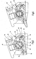
- Im folgenden wird die erfindungsgemäße Vorrichtung anhand verschiedener Ausführungsbeispiele nach der Zeichnung näher erläutert. Dabei zeigen in prinzipieller und nicht maßstäblicher Darstellung die
- Fig.1
- die Bandspannvorrichtung als Ganzes in einer perspektivi- schen Ansicht mit Wickel- und Schneideinrichtung;
- Fig.2
- eine stirnseitige Seitenansicht auf einen Teil der Vorrichtung nach der
Fig.1 ohne Schneideinrichtung; - Fig.3 bis 8
- teilweise die stirnseitige Seitenansicht der Spannvorrichtung nach der
Fig.1 in verschiedenen Betriebsstellungen; - Fig.9
- einen Teil der Spannvorrichtung nach der
Fig.1 mit teilweise frei geschnittenem Gehäuse; - Fig.10 bis
- 13 eine weitere Ausführungsform der erfindungsgemäßen Vor- richtung nach den vorangegangenen Figuren;
- Fig.14 bis 17
- eine bezogen auf die Steuereinrichtung geänderte weitere Ausführungsform.
- Die
Fig.1 zeigt in perspektivischer Seitenansicht die Spannbandvorrichtung als Ganzes, die als sog. Umreifungsgerät einsetzbar ist. Jedoch ist insoweit die Vorrichtung ohne das zu spannende Band dargestellt. Die Spannvorrichtung nach derFig.1 weist eine als Ganzes mit 10 bezeichnete Antriebseinheit auf, die im betätigten Zustand eine als Ganzes mit 12 bezeichnete Bandwickeleinheit mit entgegengesetzten Drehrichtungen in jeweils einer Richtung antreibt. Mittels einer als Ganzes mit 14 bezeichneten Betätigungseinrichtung, die von einer als Ganzes mit 16 bezeichneten Steuereinrichtung der Bandwickeleinheit 14 ansteuerbar ist, was im folgenden noch näher dargestellt werden wird, ist ein inFig.1 nicht dargestelltes, in die Vorrichtung einlegbares Band 18, das man auch als Umreifungsband bezeichnet, in vorgebbaren Positionen lösbar zu arretieren. Zum Abschneiden des Bandes 18 dient im übrigen eine als Ganzes mit 20 bezeichnete Schneideinrichtung. Alle vorstehend genannten Komponenten der Spannvorrichtung sind in einem als Ganzes mit 22 bezeichneten Spanngehäuse der Vorrichtung integriert. Das dahingehende Spanngehäuse weist in Blickrichtung auf dieFig.1 gesehen auf seiner Unterseite einen plattenartigen Auflageschuh 24 auf, der es mit seiner Unterseite erlaubt, die Vorrichtung auf einem Packgut abzustützen und auf seiner gegenüberliegenden, frei liegenden Oberseite ist eine Führungsfläche 26 für die Führung des zu spannenden Bandes vorhanden. - Die
Fig.2 zeigt eine stirnseitige Ansicht der Spannvorrichtung nach derFig.1 mit teilweise weggeschnittenem Spanngehäuse 22 zwecks verbesserter Darstellung des Innenlebens der Vorrichtung und im übrigen ist bei der Darstellung nach derFig.2 die Schneideinrichtung 20 weggelassen, da in der dahingehenden Grundausführungsform die gezeigte Vorrichtung auch als reine Bandspannvorrichtung eingesetzt werden kann und das Abtrennen des Bandes 18 kann außerhalb der Vorrichtung, beispielsweise mit einer separaten Schneideinrichtung in Form eines Messers (nicht dargestellt), erfolgen. Das Band 18 ist inFig.2 in prinzipieller Darstellung wiedergegeben. Das Band18 kann ein Stahlband, ein Kunststoffband oder ein solches mit Stahl- oder Kunststoffverstärkung sein und umgreift im geschlossenen, inFig.2 gezeigten Zustand ein nicht näher dargestelltes Packgut, das in der gezeigten Umschlingungsschlaufe 30 bereits aufgenommen ist. Insbesondere kommen aus Kunststofffasern gewobene oder verleimte Gurte zum Einsatz. - Da das Band 18 meist für Standardumreifungsvorgänge eines definierten Verpackungsgutes eingesetzt wird, ist die Länge des Bandes in definierten Größenstufen insoweit dem Grunde nach vorgegeben. Für jede Art von Verpackungsgut steht insoweit dann eine definierte Bandlänge zur Verfügung, wobei das Verpackungsgut auch mehrteilig sein kann, so dass dann über das Band 18 mehrere Verpackungseinheiten in einem Verbund und mithin in einer Losgröße zusammengehalten sind. Auch dient das umgelegte und gespannte Band 18 der Aussteifung des Verpackungsgutes, so dass insbesondere bei Einsatz von Pappe als Verpackungsumhüllung die Verpackung über das Band zusätzlich gesichert ist. Die dahingehenden Zusammenhänge sind bekannt, so dass an dieser Stelle hierauf nicht mehr näher eingegangen wird. Die Bänder können vor ihrer Verarbeitung eine genau definierte Länge aufweisen, die auf das Packgut abgestimmt ist; mit der erfindungsgemäßen Vorrichtung ist aber auch der Einsatz beliebiger Bandlängen möglich.
- Zum weiteren Verständnis sei jedoch noch erwähnt, dass das Band 18 mit seinem einen freien Bandende 32, um eine Öse oder Kausche 34 in selbsthemmender Weise geschlungen ist und das andere freie Bandende 36 ist nach einer gewissen Anzahl an Umwicklungen oder Umschlingungen innerhalb der Bandwickeleinheit 12 aufgenommen. Da die Anzahl der Umwicklungen begrenzt ist, ist die Länge des Bandes immer dergestalt zu Wählen, dass nicht zu viele Wicklungen auf der Bandwickeleinheit 12 entstehen, die dann nicht mehr von dem Gerät handhabbar sind; wobei die Bandlänge aber auch nicht zu kurz sein darf, da ansonsten ein Anziehen des Bandes 18 und sein Festlegen auf der Bandwickeleinheit 12 gefährdet sein kann. Bei dem Systemzustand nach der
Fig.2 ist das Band 18 innerhalb der Spannvorrichtung geklemmt und durch Aufwickeln des Bandes 18 an der Bandwickeleinheit 12 wird die Öse oder Kausche 34 zusammen mit dem freien Bandende 32 in Richtung des Pfeiles X auf das Spanngehäuse 22 hin angezogen, was die freie Bandlänge des Spannbandes 18 verkürzt mit der Folge, dass sich das Band 18 fest um das nicht näher dargestellte Verpackungsgut legen kann. - Ist der dahingehende Spann- und Aufwickelvorgang beendet, läßt sich dann über eine separate Trenn- oder Messereinrichtung das Band 18 beispielsweise an der Schneidstelle 38 durchschneiden und der Umreifungsvorgang wäre dann insoweit abgeschlossen. Anstelle des genannten Bandes 18 als Flachkörper könnte auch ein drahtförmiger Körper stehen und es wäre dem Grunde nach auch denkbar, eine Mehrfach-Übereinanderanordnung an Bändern 18 (nicht dargestellt) derart an einem Drittgegenstand, wie einem Verpackungsgut, umreifend festzulegen. Ist an der Schneidstelle 38 das Band 18 aber insoweit abgeschnitten, wird über die Selbsthemmung der Ösen- oder Spangenteile für die Öse 34 das Band 18 in seiner gespannten Lage arretierend festgehalten.
- Die in
Fig.2 gezeigte Steuereinrichtung 16 weist ein erstes Steuerteil 40 mit Steuernocken 42 auf. Die dahingehenden Steuernocken 42 erstrecken sich einander diametral gegenüberliegend um die Längsachse 44 der Bandwikkeleinheit 12. Ferner ist ein zweites Steuerteil 46 vorgesehen mit einer weiteren Art an Steuernocke 48. Die dahingehende Steuernocke 48 ist nur einmal vorhanden und erstreckt sich mit ihrem Außendurchmesser längs eines im Durchmesser größeren Teilkreises, denn bezogen auf den Schwenkkreis der Steuernocken 42 in ihrer maximal möglichen, ausgeschwenkten Stellung. Beide Steuerteile 40,46 sind zumindest in einer Richtung von der Wickelwelle 50 der Bandwickeleinheit 12 mitnehmbar. Der genannte Teilkreis muß jedoch nicht zwingend größer sein. Die Wickelwelle 50 ist insoweit als zylindrischer Mitnahmezapfen ausgebildet und weist in der Mitte einen durchgehenden Längsschlitz 52 auf, der der Mitnahme des Endbereiches des weiteren Bandendes 36 dient. Anstelle eines Längsschlitzes können auch mehrere Längsschlitze vorhanden sein. Sofern fünf Steuernocken 42 zum Einsatz kommen, wird eine diametral gegenüberliegende Anordnung durch eine solche abgelöst, bei der die Abstände der Steuernocken 42 in radialer Umfangsrichtung zueinander gleich sind. In jedem Fall befinden sich bevorzugt die Steuernocken 42 auf demselben Teilkreis. - Einer der beiden Steuerteile, hier das Steuerteil 40, ist derart mit einer Freilaufeinrichtung versehen, dass in einer der beiden möglichen Drehrichtungen, hier in Blickrichtung auf die
Fig.2 gesehen, im Uhrzeigersinn das zweite Steuerteil 46 von der Wickelwelle 50 ohne Kraftübertragung mitnehmbar ist oder seine eingenommene Stellung beibehält. Insoweit behalten auch die Steuernocken 42 des Steuerteils 40 ihre gezeigte Lage bei und drehen zusammen mit dem zweiten Steuerteil 46 entgegen dem Uhrzeigersinn. In der anderen Richtung, die inFig.2 mit dem Pfeil Y gekennzeichnet ist und mithin entgegen dem Uhrzeigersinn, werden die Steuerteile 40,46 tendenziell in der anderen Richtung bewegt, wobei dann das zweite Steuerteil 46 mit seinem Steuernocken 48 ein Widerlager bildet für Teile der Betätigungseinrichtung 14. Die genannte Freilaufeinrichtung wird gemäß der Darstellung nach derFig.1 über einzelne Freilaufkörper 54 realisiert, die in inneren und äußeren Ringteilen des Spanngehäuses 22 und der Bandwickeleinheit 12 aufgenommen sind, wobei dahingehende Freilaufeinrichtungen Stand der Technik sind, so dass an dieser Stelle hierauf nicht mehr näher eingegangen wird. - Wie sich des weiteren aus der
Fig.2 ergibt, ist die Betätigungseinrichtung 14 aus einem mehrteiligen Hebeltrieb bestehend aufgebaut, wobei der als Winkelhebel ausgebildete Hebel 56 von dem ersten Steuerteil 40 mit seinen Steuernocken 42 ansteuerbar ist. Ein weiterer Hebel 58, der gleichfalls in der Art eines Winkelhebels ausgebildet ist, ist von dem zweiten Steuerteil 46 mit seiner Steuernocke 48 ansteuerbar. Beide Hebel 56,58 weisen zu ihrer Betätigung an ihrem freien Ende eine Kurvenrolle 60 auf, damit sie besser an den Bahnen, gebildet durch die Steuernocken 42,48, abgleiten können. Der weitere Hebel 58 ist an seinem anderen freien Ende über eine Drehachse 62 schwenkbar im Spanngehäuse 22 gelagert. An dem Hebel 58 ist ein weiterer Betätigungshebel 64 starr angelenkt, der über eine weitere Gelenkstelle 66 die fußartige Arretiereinrichtung 68 für das Festklemmen oder Festspannen des Bandes 18 trägt. An der Unterseite ist die Arretiereinrichtung 68 gemäß der Darstellung nach derFig.2 mit einer Riffelung versehen, um dergestalt die Eingriffskraft in die Bandoberfläche 18 zu erhöhen. - Im Bereich des unteren Drittels des Betätigungshebels 64 ist in Blickrichtung auf diesen hinter ihm der Hebel 56 über eine dritte Drehachse 70 angelenkt. Ein Energiespeicher in Form einer Zugfeder 72 versucht das hintere Winkelstück des Winkelhebels 56 um die dritte Drehachse 70 entgegen dem Uhrzeigersinn zu verschwenken. Ferner drückt ein weiterer Energiespeicher in Form der Druckfeder 74 das obere Hebelende des Hebels 58 entgegen dem Uhrzeigersinn. Die dahingehende Druckfeder 74 ist nur als Funktionselement insoweit in der
Fig.2 dargestellt und wird im übrigen gemäß der Darstellung nach derFig.9 durch eine Schenkelfeder 76 bei der praktischen Umsetzung insoweit realisiert. Die genannten Zug- und Druckfedern können auch durch Druck- bzw. Zugfedern ersetzt werden, die jedoch an anderer Stelle dann sinnfällig mit ihrer benötigten Kraftwirkung ansetzen. Ferner weist der Winkelhebel 56 an seinem der Kurvenrolle 60 entgegengesetzten Ende eine Anlageflanke 78 auf, die in der Funktionsstellung nach derFig.2 in Anlage mit einer Raststütze 80 ist, die im Bereich des möglichen Abgleitens der Anlageflanke 78 mit einer konvexen Führungsbahn 82 versehen ist. Die dahingehende Raststütze 80 ist unter Bildung eines Widerlagers für den genannten Teil des Hebeltriebes mit dem Gehäuse 22 der Spannvorrichtung fest verbunden und Teil desselben. - Die Antriebseinheit 10 besteht vorzugsweise aus einem Pneumatikmotor; könnte aber auch ein Elektromotor oder dergleichen sein. Der stangenartig ausgebildete Pneumatikmotor mündet an seiner einen freien Stirnseite in ein Antriebsritzel 84 aus, das insoweit mit einem Endlos-Schneckentrieb 86 kämmt, der insoweit die Wickelwelle 50 der Bandwickeleinheit 12 antreibt, und zwar je nach Antriebsdrehrichtung des Pneumatikmotors entgegen dem Uhrzeigersinn (Pfeil Y) oder in der entgegengesetzten Richtung Z (s.
Fig.7 ). Insoweit sind die Gehäuseteile des Pneumatikmotors außen auf das Spanngehäuse 22 aufgesetzt und die drehbaren Teile des Pneumatikmotors, insbesondere in Form des Antriebsritzels 84, innerhalb des Gehäuses 22 geführt. - Die Steuernocken 42 (insgesamt sechs Stück) des ersten Steuerteils 40 sind in diskreten Abständen voneinander längs einer geschlossenen Kurvenbahn sich erstreckend angeordnet, die konzentrisch zu der Wickelwelle 50 verläuft, wobei in der vorliegenden Ausführungsform die Steuernocken 42 um eine Schwenkachse 88 gegen die Wirkung eines weiteren Energiespeichers in Form von Druckfedern 90 bewegbar sind. Eine andere Anzahl an Steuernocken 42 ist möglich. Insoweit sind die schwenkbaren Steuernocken 42 in mindestens der Drehrichtung Y der Wickelwelle 50 in einer Ansteuerposition für Teile des Hebeltriebs in Form der Kurvenrolle 60 des Winkelhebels 56 gehalten. Das zweite Steuerteil 46 weist, wie bereits dargelegt, eine Steuernocke 48 auf, die außenumfangsseitig eine Art Evolventenbahn bildet mit zu ihrem freien Ende hin konisch zulaufenden Steuerflanken 92,94, von denen eine 92 eine Widerlagerfläche für Teile des Hebeltriebes bildet in Form der Kurvenrolle 60 für den oberen Winkelhebel 58.
- Die Ausführungsform nach der
Fig.2 ist ohne Schneideinrichtung dargestellt, wobei die in derFig.2 gezeigte Anordnung genügt, um für ein Band 18 einen Festlegevorgang veranlassen zu können. In Ergänzung der Ausführungsform nach derFig.2 wird im folgenden anhand derFig.3 bis 8 unter Einbezug der Schneideinrichtung 20 ein vollständiger Festlegezyklus für das Band 18 beschrieben, das aber insoweit in den Figuren nur teilweise und nur mit seinen relevanten Bereichen dargestellt ist. - Die in den Fig.3ff gezeigte Schneideinrichtung ist drehbar und vergleichbar der Wickelwelle 50 als Hohlhülse 96 ausgebildet, die im erweiterten Innenumfangsbereich ein stegartig vorstehendes Schneidmesser 98 aufweist, dessen freie Schneidkante in Richtung des durchgehenden Längsschlitzes 100 ragt, wobei das Schneidmesser 98 als drehbare Schneideinrichtung 20 mit einem Dreieckshebel 102 verbunden ist (vgl.
Fig.3 ), der über einen Stangentrieb 104 über den Hebeltrieb ansteuerbar ist, der insoweit über ein Hebelstück 106 schwenkbar an der Längsstange des Stangentriebes 104 angreift, wobei der Stangentrieb 104 an seinem anderen gegenüberliegenden freien Ende gelenkig am Ende des Dreieckshebels 102 angelenkt ist. Wie die Fig. 3ff zeigen, bleibt die Hohlhülse 96 in ihrer Position und das Schneidmesser 98 wird über den Stangentrieb 104 und den Hebeltrieb mit dem Hebelstück 106 entgegen dem Uhrzeigersinn von seiner Schneidposition nach derFig.3 in eine Neutralposition nach derFig.5 innerhalb der Hohlhülse 96 verschwenkt und im Uhrzeigersinn wiederum in eine Schneidstellung nach derFig.8 . - Gemäß der Ausgangs- oder Grundstellung nach der
Fig.3 ist das Schneidmesser 48 in Schneidstellung gehalten und die Arretiereinrichtung 68 ist in der geöffneten Position, d.h. die zugehörige Fuß- oder Klemmplatte ist, wie dargestellt, nach oben über den Hebeltrieb abgehoben. Die Antriebseinrichtung 10 ist nicht betätigt und das Band 18 wird, was nicht näher dargestellt ist, um das Packstück oder Verpackungsgut herumgelegt und in die Festlegeschnalle in Form der Öse 34 gemäß der Darstellung nach derFig.2 eingeführt. Ferner wird das genannte Band 18 auf die Führungsfläche 26 des Gehäuses 22 aufgelegt, indem das Band 18 zwischen der Arretiereinrichtung 68 und der Führungsfläche 26 hindurchgezogen wird. Das obere freie Bandende ist insoweit noch nicht in die genannte Spannvorrichtung eingeführt. - Gemäß den Darstellungen nach den
Fig.4 und5 wird dann die Antriebseinheit 10 eingeschaltet und es kommt zu der Drehrichtung Y im Gegenuhrzeigersinn. Aufgrund des Schneckenantriebes in Form der Endlosschnecke 86 entsteht die dahingehende Drehrichtung entgegen dem Uhrzeigersinn, wobei insoweit dann auch die Wickelwelle 50 entgegen dem Uhrzeigersinn drehend mitgenommen ist. Die an dem scheibenförmigen ersten Steuerteil 40 angelenkten Steuernocken 42 betätigen den Winkelhebel 56 über seine vorstehende Führungsrolle 60. Der dahingehende Winkelhebel 56 wird dann im Uhrzeigersinn von dem vorstehenden Ende des insoweit in Eingriff befindlichen Steuernockens 42 wegbewegt, und zwar durch Schwenken um die Schwenkachse 70, so dass insoweit der weitere Winkelhebel 58 freigegeben ist und dieser im Gegenuhrzeigersinn drehen kann, und zwar um die Schwenkachse 62, was so lange geschieht, bis die Klemmplatte der Arretiereinrichtung 68 gemäß Darstellung nach derFig.5 unter Federkraft des Energiespeichers 74 nach unten bewegt ist und dergestalt das Band 18 klemmt. - Über den Hebeltrieb, der in der Art eines Kniehebeltriebes ausgebildet sein kann, würde dann insoweit zwischen den bewegbaren Hebelteilen eine "Überzenterung" stattfinden, was die Klemmkraft für die Arretiereinrichtung 68 entsprechend erhöht. Bei der dahingehenden Position ist der Winkelhebel 58 gemäß Darstellung nach der
Fig.5 mit seiner Führungsrolle 60 in Anlage mit der Flanke 94 des Steuernockens 48. Bis zur Klemmung des Bandes 18 innerhalb der Arretiereinrichtung 68 dient der dahingehende Ansteuervorgang auch dazu, das freie Bandende durch den Längsschlitz 100 innerhalb der Hohlhülse 96 zu führen und des weiteren für einen Aufwickelvorgang das Bandende in den Längsschlitz 52 der Wickelwelle 50 eingreifen zu lassen. Um den dahingehenden Vorgang zu ermöglichen, ist durch Zurückverschwenken des Stangentriebes 104 über das am Winkelhebel 58 angelenkte Hebelstück 106 das Schneidmesser 98 aus seiner Schneidstellung nach denFig.3 und 4 in die obere inaktive Stellung nach derFig.5 verbracht, bei der die scharfe Messerkante parallel zum Längsschlitz 100 der Schneideinrichtung 20 verläuft. Die dahingehende Mitnahme des Hebelstückes 106 entgegen dem Uhrzeigersinn um die Schwenkachse 62 ist durch die Zustellbewegung des Hebels 58 unter dem Wirkungseinfluß der Druckfeder 74 veranlaßt. - Wie sich des weiteren aus den
Fig.3 bis 5 ergibt ist die Anlageflanke 78 des Winkelhebels 56 zunächst abstützend in Anlage mit der freien Stirnseite der Raststütze 80 und aufgrund der beschriebenen Hebelbewegung wird zunächst die Anlageflanke 78 entlang des konkaven stirnseitigen Bahnverlaufs der Raststütze 80 geführt bis zu einem Untergriffspunkt, bei dem dann ein Entlanggleiten entlang des unteren konvexen Führungsbahnverlaufs 82 der genannten Raststütze 80 veranlaßt ist; eine Bewegung, die unterstützt wird durch die Zugfederanordnung 72, wobei die Zugfeder 72 mit ihren beiden freien Enden einmal am Betätigungshebel 64 angelenkt ist und einmal am Winkelhebel 56 im Bereich der Angriffsflanke 78. Sobald die Position nach derFig.5 eingenommen ist, wird die Antriebseinheit 10 gestoppt. Das An- und Abschalten der Antriebseinheit 10 in Form des Pneumatikmotors geschieht mittels nicht näher dargestellter Betätigungsknöpfe, die aber insoweit eine Einhandbedienung für die gesamte Spannvorrichtung zulassen, und für jede Drehrichtung der Antriebseinheit 10 ist ein auf die Richtung hinweisender Betätigungsknopf vorzugsweise vorgesehen. - Gemäß Darstellung nach der
Fig.6 ist die Antriebseinheit 10 wieder eingeschaltet worden und die Wickelwelle 50 hat gemäß der Umdrehungsrichtung Y mehrere Aufwickelvorgänge für das Bandende 36 veranlaßt. Das zweite Steuerteil 46 mit der Steuernocke 48 ist dann über Reibschluß so lange mitgenommen worden, bis die als Widerlagerfläche dienende Flanke 92 in untergreifende Anlage mit der Führungsrolle 60 des weiteren Hebels 58 kommt. Nun kann das Band durch Betätigung der Wickelwelle 50 weiter aufgewickelt werden und wird bis zur Erreichung einer eingestellten Spannkraft, die über den Pneumatikmotor von seiner möglichen Druckbilanz her vorgegeben ist, gespannt, d.h. in Blickrichtung auf dieFig.2 gesehen wird die Öse oder Kausche 34 in Richtung des Pfeiles X zu dem Spanngehäuse 22 der Vorrichtung gezogen und insoweit das Packstück kraft- und formschlüssig umreift. Kommt es überraschend vorher zu einer übermäßigen Aufwicklung von Bandmaterial an der Wickelwelle 50, wäre insoweit der Antrieb 10 von Hand abzuschalten. - In Weiterführung des Verfahrensganges wird dann gemäß den Darstellungen nach den
Fig.7 und 8 wiederum die Antriebseinheit 10 eingeschaltet und es ergibt sich eine Drehrichtung gemäß Darstellung nach derFig. 7 in Z-Richtung für die Wickelwelle 50. Mithin dreht diese nun im Uhrzeigersinn. Bei der dahingehenden Gegenbewegung wird der Bandzug des Bandes 18 an der Stelle der Klemmung, sprich im Bereich der Arretiereinrichtung 68, entlastet und gleichzeitig wird über den bereits angesprochenen Freilauf oder die Freilaufeinrichtung 54 der Steuernocken 48 des zweiten Steuerteils 46 vom Anschlag weg im Uhrzeigersinn Z mitgenommen. Nach ca. einer ¾ Umdrehung kommt nunmehr die Flanke 94 des Steuernockens 48 mit der Führungsrolle 60 des Hebels 58 in Kontakt und der Betätigungshebel 58 wird gegen die Federkraft des Energie- oder Federspeichers in Form einer Druck- oder Schenkelfeder 74 im Uhrzeigersinn um die Schwenkachse 62 bewegt. Bedingt durch die dahingehende Bewegung des Hebels 56 wird gemäß der Darstellung nach derFig.8 die Klemmplatte der Arretiereinrichtung 68 abgehoben und gibt dann insoweit das Band 18 frei. Im obersten Kurvenpunkt passiert dann der Hebel 58 mit seiner Anlageflanke 78 die Kante der feststehenden Raststütze 80 und wird dann mittels Federkraft entgegen dem Uhrzeigersinn um die Schwenkachse 64 verdreht und stützt sich dann wiederum an der freien Stirnseite der Raststütze 80 ab. Demgemäß wird der dahingehende Betätigungshebel 56 in dieser Lage bei geöffneter Klemme festgehalten. - Mit der Öffnung der Bandklemmung wird über den Stangentrieb 104 das Schneidmesser 98 über den Dreieckshebel 102 im Uhrzeigersinn verschwenkt und dergestalt in seine in der
Fig.8 dargestellte Schneidposition gebracht. In dieser Schneidposition nach derFig. 8 wird an der dortigen Stelle dann das Band 18 endseitig durchschnitten. Diean der Kurvenrolle 60 des Winkelhebels 56 vorbeigleitenden, federbelasteten Steuernocken 42 werden insoweit gegen die Federkraft weggeklappt oder weggeschwenkt und behindern insoweit den Freigabevorgang für das Band nicht. Anschließend ist wiederum die Antriebseinheit 10 auszuschalten und im Hinblick auf das abgeschnittene Band 18 bei geöffneter Bandklemmung kann die Spannvorrichtung entfernt werden. Der gemäß Darstellung nach derFig.8 auf der Wickelwelle 50 verbleibende Bandrest kann dann von Hand ohne weiteres entfernt werden. Die Bandspannvorrichtung steht dann für einen erneuten Spannvorgang gemäß ihrer Ausgangsstellung nach derFig.3 zur Verfügung. - Bei einer Ausführungsvariante nach den
Fig. 10 bis 13 ist das scheibenförmige Steuerteil 40, das mit der Wickelwelle 50 zusammenwirkt, mit feststehenden Steuernocken 42a ausgestattet anstelle der federbelasteten, bewegbaren Steuernocken 42. Um hier eine Gleichwirkung zu der vorausgehend beschriebenen Lösung zu erreichen, ist neben dem bereits beschriebenen Winkelhebel 56 ein weiterer Winkelhebel 108 vorzusehen, der zu dem Hebel 56 die gleiche Schwenkachse 70 hat und der im übrigen an seinem freien Ende mit einem Übergriffsstück 110 (vgl.Fig.12 ) den anderen Winkel 56 im Bereich der Anlageflanke 78 endseitig übergreift. In dieser Anlageposition ist der Winkelhebel 108 über eine weitere Zugfeder 112 gehalten. Insoweit wird über das Übergriffsstück 110 sichergestellt, dass der Winkelhebel 56 mit seiner Anlageflanke 78 in Untergriff mit der feststehenden Raststütze 80 gemäß vorstehender Beschreibung (vgl.Fig.13 ) kommen kann. - Bei einer weiteren Lösungsalternative nach den
Fig. 14 bis 17 weist die Steuerscheibe als erstes Steuerteil 40 mit dieser fest verbunden in Blickrichtung auf dieFig. 14 und 16 gesehen nach hinten vorstehende Steuernocken 42b auf. Wird wiederum, wie bereits dargelegt, die Antriebseinheit 10 eingeschaltet, soll sich die Drehrichtung Y ergeben und die Wickelwelle 50 dreht mithin im Gegenuhrzeigersinn. Als Steuerscheibe dient die Mitnahmescheibe 114, die fest mit der Wickelwelle 50 verbunden ist. Eine Betätigungsscheibe 116, die mittels einer üblichen Lagerstelle 118, die jedoch mit einem Freilauf versehen ist, auf der Wickelwelle drehbar geführt ist, weist einen federbelasteten Betätigungsstift 120 auf, der in Blickrichtung auf dieFig. 14 und 15 gesehen einen vorstehenden Betätigungszapfen 122 insoweit in Anlage hält mit dem vorspringenden, darunterliegenden, feststehenden Steuernocken 42b. Wenn die Betätigungsscheibe 116 in Drehrichtung Y weiter verschwenkt wird, kommt der Betätigungsstift 120 in Anlage mit dem Steuergehäuseteil 124 und gemäß den Darstellungen nach denFig.16 und 17 wird entgegen der Betätigungskraft der Federanordnung der Betätigungsstift 120 nach innen gedrückt und der Betätigungszapfen 122 gerät nach innen geführt außer Eingriff mit dem dahingehenden Steuernokken 42b. Dies führt zu einer Entkupplung der Steuerscheibe 114 als Steuerteil 14 und die Wickelwelle 50 kann insoweit im Gegenuhrzeigersinn Y weitergedreht werden. Hierbei gerät die Steuerflanke 92 wiederum in Anlage und in Untergriff mit dem Hebel 58 und die vorher hierzu getroffenen Ausführungen für den weiteren Bewegungsablauf gelten insoweit auch für die vorgestellte, geänderte Ausführungsform.
Claims (9)
- Vorrichtung zum Spannen eines Bandes, insbesondere Umreifungsgerät, mit einer Antriebseinheit (10), die im betätigten Zustand eine Band-Wickeleinheit (12) mit entgegengesetzten Drehrichtungen in jeweils einer Richtung antreibt, wobei mittels einer Betätigungseinrichtung (14), die von einer Steuereinrichtung (16) der Band-Wickeleinheit (12) ansteuerbar ist, das in die Vorrichtung einlegbare Band (18) in vorgebbaren Positionen lösbar arretiert ist, dadurch gekennzeichnet, dass die Steuereinrichtung (16) ein erstes Steuerteil mit Steuernocken (42) aufweist, sowie ein zweites Steuerteil (46) mit mindestens einer weiteren Steuernocke (48), dass beide Steuerteile (40,46) zumindest in einer Richtung von der Wickelwelle (50) der Band-Wickeleinheit (12) mitnehmbar sind, und dass mindestens eine (46) der beiden Steuerteile (40,46) derart mit einer Freilaufeinrichtung (54) versehen ist, dass in einer der beiden möglichen Drehrichtungen das genannte Steuerteil (46) von der Wikkelwelle (50) ohne Kraftübertragung mitnehmbar ist und/oder dieses in seiner Mitnahmeposition verharrt.
- Vorrichtung nach Anspruch 1, dadurch gekennzeichnet, dass die Betätigungseinrichtung (14) aus einem mehrteiligen Hebeltrieb besteht, dass mindestens ein Hebel (56) des Triebes von dem ersten Steuerteil (40) ansteuerbar ist und mindestens ein weiterer Hebel (58) von dem zweiten Steuerteil (46) und dass an einem freien Ende des Hebeltriebes ein Teil einer Arretiereinrichtung (68) vorgesehen ist, die das in die Vorrichtung einlegbare Band (18) in den vorgegebenen Positionen lösbar arretiert.
- Vorrichtung nach Anspruch 1 oder 2, dadurch gekennzeichnet, dass die Steuernocken (42) des ersten Steuerteils (40) sich in diskreten Abständen voneinander längs einer geschlossenen Kurvenbahn erstrecken, die konzentrisch zu der Wickelwelle (50) angeordnet ist und dass die Steuernocken (42a,42b) zumindest teilweise starrer Bestandteil einer Steuerscheibe (114) sind oder dass die Steuernocken (42) zumindest teilweises gegen die Wirkung eines Energiespeichers (90) bewegbar, in mindestens einer Drehrichtung (Y) der Wickelwelle (50) in einer Ansteuerposition für Teile (60,56) des Hebeltriebs gehalten sind.
- Vorrichtung nach einem der Ansprüche 1 bis 3, dadurch gekennzeichnet, dass das zweite Steuerteil (46) mindestens eine Steuernocke (48) aufweist mit zu ihrem freien Ende hin konisch zulaufenden Steuerflanken (92,94), von denen eine (92) eine Widerlagefläche für Teile (60,58) des Hebeltriebs bildet.
- Vorrichtung nach einem der Ansprüche 1 bis 4, dadurch gekennzeichnet, dass die bewegbaren Komponenten zumindest teilweise in einem handhabbaren Gehäuse (22) integriert sind, das im Bereich des Hebeltriebes eine Raststütze (80) aufweist, die ein Widerlager für einen Teil (78) des Hebeltriebes bildet, sobald der genannte Teil (78) an der Raststütze (80) angreift.
- Vorrichtung nach einem der Ansprüche 1 bis 4, dadurch gekennzeichnet, dass Teile (56;58) des Hebeltriebes unter Einsatz mindestens eines weiteren Energiespeichers (72;74) in ihrer wirksamen Anlagestellung mit der Steuereinrichtung (42; 46) gehalten sind.
- Vorrichtung nach einem der Ansprüche 1 bis 6, dadurch gekennzeichnet, dass diese mit einer drehbaren Schneideinrichtung (20) für das Band (18) versehen ist, das insoweit in einer Schlitzführung (100) führbar ist, die mit mindestens einem Schneidmesser (98) versehen in einer Drehstellung das Durchtrennen des Bandes (18) erlaubt.
- Vorrichtung nach Anspruch 7, dadurch gekennzeichnet, dass zum Antreiben der drehbaren Schneideinrichtung (20) ein Stangentrieb (104) dient, der von Teilen (106) des Hebeltriebes betätigbar ist.
- Vorrichtung nach einem der Ansprüche 1 bis 8, dadurch gekennzeichnet, dass als Antriebseinheit (10) ein Pneumatikmotor mit zwei entgegengesetzten Drehrichtungen vorgesehen ist, der über einen Schneckentrieb (86) mit der Band-Wickeleinheit (12) zusammenwirkt.
Applications Claiming Priority (2)
| Application Number | Priority Date | Filing Date | Title |
|---|---|---|---|
| DE102006010912A DE102006010912A1 (de) | 2006-03-09 | 2006-03-09 | Vorrichtung zum Spannen eines Bandes |
| PCT/EP2007/001663 WO2007101583A1 (de) | 2006-03-09 | 2007-02-27 | Vorrichtung zum spannen eines bandes |
Publications (2)
| Publication Number | Publication Date |
|---|---|
| EP1991464A1 EP1991464A1 (de) | 2008-11-19 |
| EP1991464B1 true EP1991464B1 (de) | 2011-03-23 |
Family
ID=38051781
Family Applications (1)
| Application Number | Title | Priority Date | Filing Date |
|---|---|---|---|
| EP07711682A Not-in-force EP1991464B1 (de) | 2006-03-09 | 2007-02-27 | Vorrichtung zum spannen eines bandes |
Country Status (5)
| Country | Link |
|---|---|
| US (1) | US7669526B2 (de) |
| EP (1) | EP1991464B1 (de) |
| AT (1) | ATE502854T1 (de) |
| DE (2) | DE102006010912A1 (de) |
| WO (1) | WO2007101583A1 (de) |
Families Citing this family (9)
| Publication number | Priority date | Publication date | Assignee | Title |
|---|---|---|---|---|
| KR200453169Y1 (ko) | 2008-10-24 | 2011-04-11 | 대우조선해양 주식회사 | 선박용 케이블 타이 결속장치 |
| WO2014008493A2 (en) | 2012-07-05 | 2014-01-09 | Golden Bear LLC | Externally-powered strapping tool and a strapping tool assembly utilized therein |
| US10604286B2 (en) * | 2014-05-08 | 2020-03-31 | Encore Packaging Llc | Tool for tightening strapping |
| US11066200B2 (en) * | 2017-11-27 | 2021-07-20 | Daniels Manufacturing Corporation | Apparatus for tensioning a cable lacing tape device |
| US11046466B2 (en) * | 2017-11-27 | 2021-06-29 | Daniels Manufacturing Corporation | Apparatus for tensioning a cable lacing tape device |
| US11174051B2 (en) | 2019-02-15 | 2021-11-16 | Samuel, Son & Co. (Usa) Inc. | Hand held strapping tool |
| TWM585235U (zh) * | 2019-05-10 | 2019-10-21 | 長諺工業股份有限公司 | 具有減速裝置的打包機 |
| WO2024010851A1 (en) | 2022-07-06 | 2024-01-11 | Daniels Manufacturing Corporation | Apparatus for tensioning a cable lacing tape |
| US12397943B2 (en) | 2022-11-29 | 2025-08-26 | Samuel, Son & Co. (Usa) Inc. | Handheld strapping device |
Family Cites Families (10)
| Publication number | Priority date | Publication date | Assignee | Title |
|---|---|---|---|---|
| US3189060A (en) * | 1962-04-03 | 1965-06-15 | Fmc Corp | Strap tensioning tool |
| DK214079A (da) * | 1978-05-25 | 1979-11-26 | Gerrard Ind Ltd | Emballageombindingsvaerktoej |
| US4252158A (en) * | 1979-07-06 | 1981-02-24 | Fmc Corporation | Strap tensioning tool |
| WO1984000023A1 (fr) * | 1982-06-15 | 1984-01-05 | Andras Banai | Appareil manuel pour le serrage des bandes pour lier des objets |
| US4605456A (en) * | 1985-05-02 | 1986-08-12 | Signode Corporation | Method and apparatus for feeding and tensioning strap in a strapping machine |
| DE58905827D1 (de) * | 1988-09-08 | 1993-11-11 | Strapex Ag Wohlen | Spann- und Verschliessgerät für ein Umreifungsband aus Kunststoff. |
| US6131634A (en) | 1999-05-27 | 2000-10-17 | Chang; Jeff Chieh Huang | Portable strapping apparatus |
| DE10026200A1 (de) | 2000-05-26 | 2001-11-29 | Cyklop Gmbh | Vorrichtung zum Spannen von Umreifungsbändern |
| US6708606B1 (en) * | 2002-10-31 | 2004-03-23 | Illinois Tool Works, Inc. | Strapper with improved winder |
| US6962108B1 (en) * | 2004-06-23 | 2005-11-08 | Hsiu-Man Yu Chen | Strap-guiding device for a strapping packaging apparatus |
-
2006
- 2006-03-09 DE DE102006010912A patent/DE102006010912A1/de not_active Withdrawn
-
2007
- 2007-02-27 DE DE502007006771T patent/DE502007006771D1/de active Active
- 2007-02-27 EP EP07711682A patent/EP1991464B1/de not_active Not-in-force
- 2007-02-27 US US12/224,714 patent/US7669526B2/en active Active
- 2007-02-27 AT AT07711682T patent/ATE502854T1/de active
- 2007-02-27 WO PCT/EP2007/001663 patent/WO2007101583A1/de not_active Ceased
Also Published As
| Publication number | Publication date |
|---|---|
| DE102006010912A1 (de) | 2007-09-13 |
| WO2007101583A1 (de) | 2007-09-13 |
| US7669526B2 (en) | 2010-03-02 |
| US20090071350A1 (en) | 2009-03-19 |
| EP1991464A1 (de) | 2008-11-19 |
| ATE502854T1 (de) | 2011-04-15 |
| DE502007006771D1 (de) | 2011-05-05 |
Similar Documents
| Publication | Publication Date | Title |
|---|---|---|
| EP1991464B1 (de) | Vorrichtung zum spannen eines bandes | |
| DE3102242C2 (de) | ||
| EP1283797B1 (de) | Vorrichtung zum spannen von umreifungsbändern | |
| EP0075252B1 (de) | Automatische Bindeeinrichtung für Maschinen zum Herstellen von zylindrischen Ballen aus Erntegut in einer Wickelkammer | |
| DE2628608C3 (de) | Vorrichtung zum Umbinden eines Gegenstandes | |
| DE102005013901A1 (de) | Baumständer, insbesondere Christbaumständer mit verbesserter Lösefunktion | |
| DE60129759T2 (de) | Bindevorrichtung zum Spannen eines Bindestreifens | |
| DE19705584B4 (de) | Garnsicherungsvorrichtung | |
| DE2165664C3 (de) | Vorrichtung zum Umbinden von mehreren Gegenständen mit einer Bandschlaufe | |
| DE3644657C2 (de) | ||
| DE3337184A1 (de) | Aufwickel- und spannvorrichtung fuer ein lasthalteband | |
| WO1989001227A1 (fr) | Outil de ficelage de faisceaux de cables ou similaires avec un ruban sans fin | |
| DE2910989C2 (de) | Zangenartiges Werkzeug zum Anbinden der Triebe von Kulturgehölzen | |
| DE3536955A1 (de) | Vorrichtung zum buendeln oder umwickeln von laenglichen dingen | |
| DE3638882C2 (de) | ||
| DE102011076278B4 (de) | Abbindevorrichtung für Pressballen | |
| DE602004006616T2 (de) | Vorrichtung zum anbringen von bindfäden an süssigkeiten | |
| DE1586502C (de) | Spannvorrichtung für Bander, insbe sondere aus Kunststoff, Textilien u dgl | |
| DE1486185C (de) | Maschine zum Umschnüren von Packstucken | |
| DE1586203C (de) | Vorrichtung zur Führung eines Bandes, insbesondere an der Verbindungsstelle von Bandanfang und Bandende bei einer Verschnürungsmaschine | |
| DE934795C (de) | Bindemechanismus fuer Ballenpressen | |
| DE1108607B (de) | Maschine zum Umschnueren von Waren, insbesondere von gestapelten Briefen, Zeitungen,Zeitschriften oder anderen Schriftstuecken | |
| DE1761124C (de) | Spann- und Schließ werkzeug für Verpackungsbänder | |
| DE1535891C (de) | Knüpfgerät zum Verknoten von Faden | |
| DE430029C (de) | Vorrichtung zum Verschnueren von Kisten, Ballen o. dgl. mittels eines Drahtes |
Legal Events
| Date | Code | Title | Description |
|---|---|---|---|
| PUAI | Public reference made under article 153(3) epc to a published international application that has entered the european phase |
Free format text: ORIGINAL CODE: 0009012 |
|
| 17P | Request for examination filed |
Effective date: 20080724 |
|
| AK | Designated contracting states |
Kind code of ref document: A1 Designated state(s): AT BE BG CH CY CZ DE DK EE ES FI FR GB GR HU IE IS IT LI LT LU LV MC NL PL PT RO SE SI SK TR |
|
| 17Q | First examination report despatched |
Effective date: 20090707 |
|
| GRAP | Despatch of communication of intention to grant a patent |
Free format text: ORIGINAL CODE: EPIDOSNIGR1 |
|
| GRAS | Grant fee paid |
Free format text: ORIGINAL CODE: EPIDOSNIGR3 |
|
| GRAA | (expected) grant |
Free format text: ORIGINAL CODE: 0009210 |
|
| AK | Designated contracting states |
Kind code of ref document: B1 Designated state(s): AT BE BG CH CY CZ DE DK EE ES FI FR GB GR HU IE IS IT LI LT LU LV MC NL PL PT RO SE SI SK TR |
|
| REG | Reference to a national code |
Ref country code: GB Ref legal event code: FG4D Free format text: NOT ENGLISH |
|
| REG | Reference to a national code |
Ref country code: CH Ref legal event code: NV Representative=s name: ISLER & PEDRAZZINI AG Ref country code: CH Ref legal event code: EP |
|
| REG | Reference to a national code |
Ref country code: IE Ref legal event code: FG4D |
|
| REF | Corresponds to: |
Ref document number: 502007006771 Country of ref document: DE Date of ref document: 20110505 Kind code of ref document: P |
|
| REG | Reference to a national code |
Ref country code: DE Ref legal event code: R096 Ref document number: 502007006771 Country of ref document: DE Effective date: 20110505 |
|
| REG | Reference to a national code |
Ref country code: NL Ref legal event code: T3 |
|
| REG | Reference to a national code |
Ref country code: GR Ref legal event code: EP Ref document number: 20110401141 Country of ref document: GR Effective date: 20110614 |
|
| PG25 | Lapsed in a contracting state [announced via postgrant information from national office to epo] |
Ref country code: LT Free format text: LAPSE BECAUSE OF FAILURE TO SUBMIT A TRANSLATION OF THE DESCRIPTION OR TO PAY THE FEE WITHIN THE PRESCRIBED TIME-LIMIT Effective date: 20110323 Ref country code: LV Free format text: LAPSE BECAUSE OF FAILURE TO SUBMIT A TRANSLATION OF THE DESCRIPTION OR TO PAY THE FEE WITHIN THE PRESCRIBED TIME-LIMIT Effective date: 20110323 Ref country code: SE Free format text: LAPSE BECAUSE OF FAILURE TO SUBMIT A TRANSLATION OF THE DESCRIPTION OR TO PAY THE FEE WITHIN THE PRESCRIBED TIME-LIMIT Effective date: 20110323 |
|
| LTIE | Lt: invalidation of european patent or patent extension |
Effective date: 20110323 |
|
| PG25 | Lapsed in a contracting state [announced via postgrant information from national office to epo] |
Ref country code: SI Free format text: LAPSE BECAUSE OF FAILURE TO SUBMIT A TRANSLATION OF THE DESCRIPTION OR TO PAY THE FEE WITHIN THE PRESCRIBED TIME-LIMIT Effective date: 20110323 Ref country code: BG Free format text: LAPSE BECAUSE OF FAILURE TO SUBMIT A TRANSLATION OF THE DESCRIPTION OR TO PAY THE FEE WITHIN THE PRESCRIBED TIME-LIMIT Effective date: 20110623 Ref country code: CY Free format text: LAPSE BECAUSE OF FAILURE TO SUBMIT A TRANSLATION OF THE DESCRIPTION OR TO PAY THE FEE WITHIN THE PRESCRIBED TIME-LIMIT Effective date: 20110323 Ref country code: FI Free format text: LAPSE BECAUSE OF FAILURE TO SUBMIT A TRANSLATION OF THE DESCRIPTION OR TO PAY THE FEE WITHIN THE PRESCRIBED TIME-LIMIT Effective date: 20110323 |
|
| REG | Reference to a national code |
Ref country code: IE Ref legal event code: FD4D |
|
| PG25 | Lapsed in a contracting state [announced via postgrant information from national office to epo] |
Ref country code: EE Free format text: LAPSE BECAUSE OF FAILURE TO SUBMIT A TRANSLATION OF THE DESCRIPTION OR TO PAY THE FEE WITHIN THE PRESCRIBED TIME-LIMIT Effective date: 20110323 Ref country code: PT Free format text: LAPSE BECAUSE OF FAILURE TO SUBMIT A TRANSLATION OF THE DESCRIPTION OR TO PAY THE FEE WITHIN THE PRESCRIBED TIME-LIMIT Effective date: 20110725 |
|
| PG25 | Lapsed in a contracting state [announced via postgrant information from national office to epo] |
Ref country code: ES Free format text: LAPSE BECAUSE OF FAILURE TO SUBMIT A TRANSLATION OF THE DESCRIPTION OR TO PAY THE FEE WITHIN THE PRESCRIBED TIME-LIMIT Effective date: 20110704 Ref country code: IS Free format text: LAPSE BECAUSE OF FAILURE TO SUBMIT A TRANSLATION OF THE DESCRIPTION OR TO PAY THE FEE WITHIN THE PRESCRIBED TIME-LIMIT Effective date: 20110723 Ref country code: RO Free format text: LAPSE BECAUSE OF FAILURE TO SUBMIT A TRANSLATION OF THE DESCRIPTION OR TO PAY THE FEE WITHIN THE PRESCRIBED TIME-LIMIT Effective date: 20110323 Ref country code: CZ Free format text: LAPSE BECAUSE OF FAILURE TO SUBMIT A TRANSLATION OF THE DESCRIPTION OR TO PAY THE FEE WITHIN THE PRESCRIBED TIME-LIMIT Effective date: 20110323 Ref country code: SK Free format text: LAPSE BECAUSE OF FAILURE TO SUBMIT A TRANSLATION OF THE DESCRIPTION OR TO PAY THE FEE WITHIN THE PRESCRIBED TIME-LIMIT Effective date: 20110323 |
|
| PLBE | No opposition filed within time limit |
Free format text: ORIGINAL CODE: 0009261 |
|
| STAA | Information on the status of an ep patent application or granted ep patent |
Free format text: STATUS: NO OPPOSITION FILED WITHIN TIME LIMIT |
|
| PG25 | Lapsed in a contracting state [announced via postgrant information from national office to epo] |
Ref country code: IE Free format text: LAPSE BECAUSE OF FAILURE TO SUBMIT A TRANSLATION OF THE DESCRIPTION OR TO PAY THE FEE WITHIN THE PRESCRIBED TIME-LIMIT Effective date: 20110323 |
|
| 26N | No opposition filed |
Effective date: 20111227 |
|
| PG25 | Lapsed in a contracting state [announced via postgrant information from national office to epo] |
Ref country code: PL Free format text: LAPSE BECAUSE OF FAILURE TO SUBMIT A TRANSLATION OF THE DESCRIPTION OR TO PAY THE FEE WITHIN THE PRESCRIBED TIME-LIMIT Effective date: 20110323 Ref country code: DK Free format text: LAPSE BECAUSE OF FAILURE TO SUBMIT A TRANSLATION OF THE DESCRIPTION OR TO PAY THE FEE WITHIN THE PRESCRIBED TIME-LIMIT Effective date: 20110323 |
|
| REG | Reference to a national code |
Ref country code: DE Ref legal event code: R097 Ref document number: 502007006771 Country of ref document: DE Effective date: 20111227 |
|
| BERE | Be: lapsed |
Owner name: GREINER G.M.B.H. & CO. KG Effective date: 20120228 |
|
| PG25 | Lapsed in a contracting state [announced via postgrant information from national office to epo] |
Ref country code: MC Free format text: LAPSE BECAUSE OF NON-PAYMENT OF DUE FEES Effective date: 20120229 |
|
| PG25 | Lapsed in a contracting state [announced via postgrant information from national office to epo] |
Ref country code: BE Free format text: LAPSE BECAUSE OF NON-PAYMENT OF DUE FEES Effective date: 20120228 |
|
| REG | Reference to a national code |
Ref country code: AT Ref legal event code: MM01 Ref document number: 502854 Country of ref document: AT Kind code of ref document: T Effective date: 20120227 |
|
| PG25 | Lapsed in a contracting state [announced via postgrant information from national office to epo] |
Ref country code: AT Free format text: LAPSE BECAUSE OF NON-PAYMENT OF DUE FEES Effective date: 20120227 |
|
| PG25 | Lapsed in a contracting state [announced via postgrant information from national office to epo] |
Ref country code: TR Free format text: LAPSE BECAUSE OF FAILURE TO SUBMIT A TRANSLATION OF THE DESCRIPTION OR TO PAY THE FEE WITHIN THE PRESCRIBED TIME-LIMIT Effective date: 20110323 |
|
| PG25 | Lapsed in a contracting state [announced via postgrant information from national office to epo] |
Ref country code: LU Free format text: LAPSE BECAUSE OF NON-PAYMENT OF DUE FEES Effective date: 20120227 |
|
| PG25 | Lapsed in a contracting state [announced via postgrant information from national office to epo] |
Ref country code: HU Free format text: LAPSE BECAUSE OF FAILURE TO SUBMIT A TRANSLATION OF THE DESCRIPTION OR TO PAY THE FEE WITHIN THE PRESCRIBED TIME-LIMIT Effective date: 20070227 |
|
| REG | Reference to a national code |
Ref country code: FR Ref legal event code: PLFP Year of fee payment: 10 |
|
| REG | Reference to a national code |
Ref country code: FR Ref legal event code: PLFP Year of fee payment: 11 |
|
| REG | Reference to a national code |
Ref country code: FR Ref legal event code: PLFP Year of fee payment: 12 |
|
| PGFP | Annual fee paid to national office [announced via postgrant information from national office to epo] |
Ref country code: GB Payment date: 20200218 Year of fee payment: 14 Ref country code: GR Payment date: 20200128 Year of fee payment: 14 |
|
| PGFP | Annual fee paid to national office [announced via postgrant information from national office to epo] |
Ref country code: CH Payment date: 20200128 Year of fee payment: 14 |
|
| PGFP | Annual fee paid to national office [announced via postgrant information from national office to epo] |
Ref country code: FR Payment date: 20200214 Year of fee payment: 14 |
|
| GBPC | Gb: european patent ceased through non-payment of renewal fee |
Effective date: 20210227 |
|
| PG25 | Lapsed in a contracting state [announced via postgrant information from national office to epo] |
Ref country code: LI Free format text: LAPSE BECAUSE OF NON-PAYMENT OF DUE FEES Effective date: 20210228 Ref country code: CH Free format text: LAPSE BECAUSE OF NON-PAYMENT OF DUE FEES Effective date: 20210228 |
|
| PG25 | Lapsed in a contracting state [announced via postgrant information from national office to epo] |
Ref country code: GR Free format text: LAPSE BECAUSE OF NON-PAYMENT OF DUE FEES Effective date: 20210906 |
|
| PG25 | Lapsed in a contracting state [announced via postgrant information from national office to epo] |
Ref country code: FR Free format text: LAPSE BECAUSE OF NON-PAYMENT OF DUE FEES Effective date: 20210228 Ref country code: GB Free format text: LAPSE BECAUSE OF NON-PAYMENT OF DUE FEES Effective date: 20210227 |
|
| PGFP | Annual fee paid to national office [announced via postgrant information from national office to epo] |
Ref country code: DE Payment date: 20220228 Year of fee payment: 16 |
|
| PGFP | Annual fee paid to national office [announced via postgrant information from national office to epo] |
Ref country code: NL Payment date: 20220221 Year of fee payment: 16 Ref country code: IT Payment date: 20220210 Year of fee payment: 16 |
|
| REG | Reference to a national code |
Ref country code: DE Ref legal event code: R119 Ref document number: 502007006771 Country of ref document: DE |
|
| REG | Reference to a national code |
Ref country code: NL Ref legal event code: MM Effective date: 20230301 |
|
| PG25 | Lapsed in a contracting state [announced via postgrant information from national office to epo] |
Ref country code: NL Free format text: LAPSE BECAUSE OF NON-PAYMENT OF DUE FEES Effective date: 20230301 |
|
| PG25 | Lapsed in a contracting state [announced via postgrant information from national office to epo] |
Ref country code: IT Free format text: LAPSE BECAUSE OF NON-PAYMENT OF DUE FEES Effective date: 20230227 Ref country code: DE Free format text: LAPSE BECAUSE OF NON-PAYMENT OF DUE FEES Effective date: 20230901 |