EP1991482B1 - Vorrichtung und verfahren zum bewegen von rollen in einer abwickelvorrichtung - Google Patents
Vorrichtung und verfahren zum bewegen von rollen in einer abwickelvorrichtung Download PDFInfo
- Publication number
- EP1991482B1 EP1991482B1 EP06832374A EP06832374A EP1991482B1 EP 1991482 B1 EP1991482 B1 EP 1991482B1 EP 06832374 A EP06832374 A EP 06832374A EP 06832374 A EP06832374 A EP 06832374A EP 1991482 B1 EP1991482 B1 EP 1991482B1
- Authority
- EP
- European Patent Office
- Prior art keywords
- reel
- station
- carriage
- longitudinal axis
- transferring
- Prior art date
- Legal status (The legal status is an assumption and is not a legal conclusion. Google has not performed a legal analysis and makes no representation as to the accuracy of the status listed.)
- Not-in-force
Links
- 238000000034 method Methods 0.000 title claims description 8
- 238000011017 operating method Methods 0.000 claims description 5
- 230000008859 change Effects 0.000 claims description 4
- 230000007246 mechanism Effects 0.000 description 8
- 230000004913 activation Effects 0.000 description 5
- 239000003638 chemical reducing agent Substances 0.000 description 4
- 239000000463 material Substances 0.000 description 2
- 238000013519 translation Methods 0.000 description 2
- 238000011144 upstream manufacturing Methods 0.000 description 2
- 230000003213 activating effect Effects 0.000 description 1
- 238000010276 construction Methods 0.000 description 1
- 230000009849 deactivation Effects 0.000 description 1
- 230000001419 dependent effect Effects 0.000 description 1
- 238000010586 diagram Methods 0.000 description 1
- 238000000605 extraction Methods 0.000 description 1
- 230000005484 gravity Effects 0.000 description 1
- 238000004519 manufacturing process Methods 0.000 description 1
- 230000002035 prolonged effect Effects 0.000 description 1
- 238000012546 transfer Methods 0.000 description 1
Images





Classifications
-
- B—PERFORMING OPERATIONS; TRANSPORTING
- B65—CONVEYING; PACKING; STORING; HANDLING THIN OR FILAMENTARY MATERIAL
- B65H—HANDLING THIN OR FILAMENTARY MATERIAL, e.g. SHEETS, WEBS, CABLES
- B65H16/00—Unwinding, paying-out webs
- B65H16/02—Supporting web roll
- B65H16/06—Supporting web roll both-ends type
-
- B—PERFORMING OPERATIONS; TRANSPORTING
- B65—CONVEYING; PACKING; STORING; HANDLING THIN OR FILAMENTARY MATERIAL
- B65H—HANDLING THIN OR FILAMENTARY MATERIAL, e.g. SHEETS, WEBS, CABLES
- B65H16/00—Unwinding, paying-out webs
- B65H16/10—Arrangements for effecting positive rotation of web roll
- B65H16/106—Arrangements for effecting positive rotation of web roll in which power is applied to web roll
-
- B—PERFORMING OPERATIONS; TRANSPORTING
- B65—CONVEYING; PACKING; STORING; HANDLING THIN OR FILAMENTARY MATERIAL
- B65H—HANDLING THIN OR FILAMENTARY MATERIAL, e.g. SHEETS, WEBS, CABLES
- B65H19/00—Changing the web roll
- B65H19/10—Changing the web roll in unwinding mechanisms or in connection with unwinding operations
- B65H19/12—Lifting, transporting, or inserting the web roll; Removing empty core
- B65H19/126—Lifting, transporting, or inserting the web roll; Removing empty core with both-ends supporting arrangements
-
- B—PERFORMING OPERATIONS; TRANSPORTING
- B65—CONVEYING; PACKING; STORING; HANDLING THIN OR FILAMENTARY MATERIAL
- B65H—HANDLING THIN OR FILAMENTARY MATERIAL, e.g. SHEETS, WEBS, CABLES
- B65H2301/00—Handling processes for sheets or webs
- B65H2301/40—Type of handling process
- B65H2301/41—Winding, unwinding
- B65H2301/413—Supporting web roll
- B65H2301/4136—Mounting arrangements not otherwise provided for
- B65H2301/41361—Mounting arrangements not otherwise provided for sequentially used roll supports for the same web roll
-
- B—PERFORMING OPERATIONS; TRANSPORTING
- B65—CONVEYING; PACKING; STORING; HANDLING THIN OR FILAMENTARY MATERIAL
- B65H—HANDLING THIN OR FILAMENTARY MATERIAL, e.g. SHEETS, WEBS, CABLES
- B65H2301/00—Handling processes for sheets or webs
- B65H2301/40—Type of handling process
- B65H2301/41—Winding, unwinding
- B65H2301/417—Handling or changing web rolls
- B65H2301/418—Changing web roll
- B65H2301/4185—Core or mandrel discharge or removal, also organisation of core removal
-
- B—PERFORMING OPERATIONS; TRANSPORTING
- B65—CONVEYING; PACKING; STORING; HANDLING THIN OR FILAMENTARY MATERIAL
- B65H—HANDLING THIN OR FILAMENTARY MATERIAL, e.g. SHEETS, WEBS, CABLES
- B65H2301/00—Handling processes for sheets or webs
- B65H2301/40—Type of handling process
- B65H2301/41—Winding, unwinding
- B65H2301/417—Handling or changing web rolls
- B65H2301/418—Changing web roll
- B65H2301/4185—Core or mandrel discharge or removal, also organisation of core removal
- B65H2301/41852—Core or mandrel discharge or removal, also organisation of core removal by extracting mandrel from wound roll, e.g. in coreless applications
- B65H2301/418526—Core or mandrel discharge or removal, also organisation of core removal by extracting mandrel from wound roll, e.g. in coreless applications by movement of the mandrel
Definitions
- the present invention relates to a device and method for moving reels in an unwinder.
- unwinders are destined to unwind web material from a reel to supply it to one or more machines located downstream in a determined work cycle.
- an unwinder comprises a bearing structure onto which two conical supports are disposed to engage two corresponding mandrels bilaterally inserted in the central tubular nucleus of the reel, also called “core”, in such a way that the reel is free to turn about the respective axis and the free unwinding of the respective web is allowed.
- An essential step during use of unwinders is the changing of the reel, that is an operation allowing replacement of a nearly empty reel with a new one.
- Such operation is most frequently carried out in an almost exclusively manual way with both the reels being stopped.
- the first reel which is nearly empty, is moved away from the support cones, between which an operator, with the aid of a mechanical lifter, subsequently fits a new reel to be unwound.
- WO 2004/000869 , WO 2004/080867 , WO 2004/043827 , US 6679451 and EP 822912 disclose examples of mechanical unwinders in which the human intervention is reduced.
- US 1949238 discloses a sheet delivering or feeding mechanism provided with means for unwinding the sheet from a roll, the unwinding mechanism maintaining the same surface speed of the roll irrespective of the diameter of the same, so that a constant even delivery is maintained, irrespective of the diameter of the roll or its variation due to the removal of the web.
- the main aim of the present invention is to solve the above mentioned drawbacks.
- the present invention it is possible to move the reels of paper which are finishing (nearly empty) in a controlled way, imposing to the same, during the reel change, a translation and a rotation with operating speeds apt to always assure an optimal control of the tension of the paper directed downstream.
- a device can be used in an unwinder of the type in which a reel nearly empty is transferred from a first station (SN) in which it rotates about its longitudinal axis until it is in a condition of "nearly total unwinding" (a condition in which its diameter reaches a predetermined value, smaller of the initial diameter) to a second station (SI) disposed at a predetermined distance from the first station (SN), and transferred again from said second station (SI) to a third station (SP) in which it can continue to rotate around its longitudinal axis until it is completely unwound, that is, until a new reel is placed in the first station (SN).
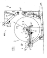
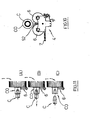
- the references (1) and (2) designate, respectively, a nearly empty reel and a new reel destined to replace the nearly empty one; the reference (S) designates the unwinder.
- the unwinder (S) has a supporting structure (SF) with an operating front (FO) on which there are defined, in correspondence of said first station (SN), support seats (AP) for the two axial ends of a reel (2).
- Such ends are formed by two conical elements (C) which can be inserted, on opposite sides, in the core (N) of the reel, said conical elements being partially projecting from the two sides of the reel and allowing the idle rotation of the reel on said support seats.
- Said conical elements (C) are disengaged from the core (N) of the reel before commanding the transferring from the station (SN) to the intermediate second station (SI).
- the moving device which is the object of the present invention is disposed and acting between said stations (SI) and (SP) and it comprises:
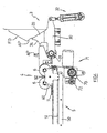
- the means (3) which execute the transferring of the nearly empty reel (1) from the first station (SN) to the intermediate second station (SI) comprise, in compliance with the example shown in the annexed drawings, two pushers (30) destined to act on said cones (C) inserted in the core (N) of the reel disposed in first station (SN), that is on the two ends of the reel projecting from said seats (AP), in order to push the reel towards the intermediate second station (SI) and, more in particular, towards the carriage (4) which is disposed in stand-by condition.
- each of said two pushers (30) is formed by a lever hinged with one of its ends to a fixed part of the structure (SF), the axis of hinge (31) being parallel to the axis of the reel (1); the lever is connected, at the opposite end, to an actuator (32) which, when activated, determines the rotation of said lever about the axis of hinge (31).
- Said pushers are disposed externally to the support seats (AP).
- AP support seats
- the arrow "A” represents the activation of the actuator (32), that is the extension of the respective rod, which corresponds to the rotation (counter-clockwise in the drawings) of the lever (30) as represented by the arrow "B".
- the deactivation of actuator (32), that is the retraction of the relevant rod involves the contrary rotation of the lever (30) and, therefore, the restoration of the normal stand-by or rest condition of this mechanism as shown in Fig.3 and Fig.4 .
- the particular mechanism utilized for transferring the reel (1) from the first station (SN) to the intermediate second station (SI) can be of any other type.
- Said carriage (4) is supported by a structure (5) developing between said intermediate second and the third station (SI, SP), that is upstream of the first station (SI) with respect to the direction (UC) of the paper exiting from the unwinder.
- said structure (5) is provided with two horizontal sides (50) developing mainly longitudinally, each of which having an external rectilinear track (51) acting, as further described below, as a guide element for the carriage (4).
- an external rectilinear track (51) acting, as further described below, as a guide element for the carriage (4).
- said track (51) is horizontal.
- Said carriage (4) comprises two forks (40), one for each of the two sides (50) of the structure (5).
- Each of said forks is provided, on its external side, with a lower "L"-shaped appendix (41) whose end slides in the track (51) of a corresponding side (50) of the structure (5). In this way, the carriage (4) is guided on the structure (5). In the figures of the annexed designs, it is visible only one of said forks (40).
- Each of said forks (40) supports two idle rubber wheels (6) having identical external diameter.
- the two wheels (6) are mounted with the respective axes (r-r) parallel to the longitudinal axis (b-b) of the reel (1), that is oriented orthogonally regarding the two arms of the respective fork (40).
- the mounting of the two wheels (6) on the fork (40) is realized by means of two corresponding pins (60) whose axes (r-r) are disposed on a same horizontal plane and whose distance is such that, given the external diameter of the wheels (6), a corresponding end of the core (N) projecting from the reel (1) can be supported on the wheels (6) free to rotate about its axis (b-b).
- the carriage (4) is a cradle supporting the nearly empty reel (1), said reel (1) being free to rotate about its longitudinal axis.
- Said carriage (4) is moved along the support structure (5) by means of a mechanism comprising, for each of the two sides of the carriage, an annular chain (7) gearing with a toothed spool fixed on the output (70) of a motor reducer (71) and engaging a plurality of guide toothed spools (72). A portion of the chain is fixed on the inner side of a correspondent fork (40).
- the movement of the chain (7) driven by the motor reducer (71) determines the movement of the carriage (4).
- the carriage (4) is represented in a plurality of operating positions, that is in the intermediate second station (SI), in the third station (SP) and in the first station (SN).
- the chain (7) is bi-directionally driven by the motor reducer (71), moving the carriage (4) alternatively between the stations (SI) and (SP), as indicated by the double arrow (G).
- the carriage (4) is provided, on each of its sides, with a brake destined to act on the wheels (6), and, therefore, to slow down the rotation of the reel (1) about its axis (b-b), as further described below.
- said brake is made of a body (8) with a concave front surface connected to a linear actuator (80) which, in turn, is fixed on the inner face of one of the two forks of the correspondent side of the carriage (4), so that the body (8) is behind one of the wheels (6).
- the brake is disposed behind the posterior wheel (6) of the couple of wheels, with the actuator being horizontally oriented.
- the carriage (4) has, in correspondence of each of its sides, a lateral appendix (42) having a concave side turned towards the top and towards the wheels (6).
- the function of said appendix (42) is described below.
- a photoelectric cell (9) controls the diameter of the reel (2) placed with the ends of its core on the support seats (AP) of the first station (SN); when the photo-cell senses that the diameter of the reel has been reduced to a predetermined value, the same photo-cell emits a signal which is transmitted to a programmable control unit (UE) -structurally and functionally known by the technicians of the industrial automation- which commands the activation of actuator (32) and, therefore, the rotation (B) of leve (30). Therefore, the reel is transferred from the first station (SN) to the intermediate second station (SI) where the carriage (4) is disposed to receive the nearly empty reel (1).
- UE programmable control unit
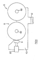
- a photoelectric cell (90), visible only in the scheme of Fig.8 senses the presence of the reel (1) on the carriage (4) and supplies, by means of the unit (UE), an assent signal for the activation of motor reducer (71) which, correspondingly driving the chain (7), moves the carriage (4) with a predetermined speed along the structure (5) until the carriage is disposed in the station (SP).
- the reel (1) is free of rotating about its axis (b-b) and, therefore, it continues to supply paper to the machines disposed downstream of the unwinder (S); moreover, the unit (UE) commands the lowering of the mechanical arm (MA), activating the respective actuators (A1, A2), arm on which a new reel is already ready for replacing the one removed from the station (SN).
- the arm (MA) is known to the technicians working in this field.
- the carriage (4) arrives to the third station (SP)
- another photoelectric cell (91) represented in the scheme of Fig.8 , by means of the unit (UE) supplies an assent signal for the activation of actuator (80) and, therefore, for the braking of the wheels (6).
- the rotational speed of the nearly empty reel (1) is controlled. This determines a more precise and effective unwinding of the reel (1), without excessive slackening of the paper which could compromise the reel change operation.
- the unwinder (S) comprises means, which can be of known type to the technicians of this field, intended to join the initial edge or head-edge of the paper supplied by the new reel (2) with the final edge or tail-edge of the paper supplied by the reel (1) disposed in the third station (SP).
- the unwinder also comprises means, which can be of known type to the technicians of the field, intended to cut the tail-edge of the paper supplied by the reel (1) disposed in the third station (SP) once said union is executed. These operations are not described in detail since they can be done according to known techniques.
- the exhausted reel (1) is then removed from the third station (SP) with the aid of a bridge crane (not visible in the drawings) or any another equipment normally available in plants making use of unwinders.
- the operating cycle of the present device differs only in that the carriage (4) is used also for delivering the exhausted reel (1) to a conveyor belt or similar means (NT) which removes the exhausted reels from the unwinder.
- said conveyor (NT) is disposed upstream and lowered with respect to the structure (5) and it is oriented parallel to the axes of reels (1, 2).
- the structure (5) is downwardly prolonged in its rear part, thus realizing a reentering portion which is inclined and downwardly oriented, so that the carriage (4) can pass over the conveyer (NT).
- the carriage (4) with the reel (1) arrives in correspondence of the conveyer (NT), after having passed the third station (SP), the reel (1) (whose core is supported by the appendixes 42 of the carriage) is intercepted by the conveyor belt which disengages it from the hooks constituted by said appendixes (42) while the carriage (4) moves downwardly.
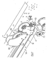
- the carriage (4) is represented in the first srtation (SN), in correspondence of the conveyor (NT) while it delivers the reel (1) to the conveyor, and in a lower and more remote position with respect to the conveyor, that is, unloaded. Therefore, a portion of the path followed by the carriage (4) is horizontal and a successive portion is diagonal or approximately vertical.
- the reference (92) indicates a sensor destined to sense the presence of the reel, mounted on the carriage (4) between the two wheels (6).
- a device in compliance with the present invention can be used in an unwinder of the type in which a nearly empty reel is transferred from a first station (SN), in which the reel rotates about its longitudinal axis until the attainment of a condition of incipient exhaustion (condition in which the diameter of the reel reaches a predetermined value which is smaller than the initial value), to a third station (SP) in which it can continue to rotate about its longitudinal axis until complete exhaustion, that is until a new reel is positioned in the first station (SN) replacing the nearly empty one.
- SN first station
- SP third station
- the working position of the carriage (4) is such that the wheels (6) can freely pass under the mandrels (C) of the reel (2), without any interference, so the carriage (4) can be freely brought back in correspondence of the station (SN) even if in the same station a new reel (2) has been positioned.
- the cones (C), with the relevant extraction/retraction mechanisms, that is engagement/disengagement of the mandrels (CO) on the axial ends of the reels, are supported by the structure of the unwinder (S) in correspondence of two sides of the same.
- the functioning and the structure of said cones (C) are known to the technicians working in this field and, therefore, it will be not described in detail.
- Fig.9 the carriage (4) is represented in the first station (SN) ad also in the third station (SP).
- An operating method in compliance with the present invention comprises, within a reel change cycle in an unwinder, a step of transferring a nearly empty reel (1) from a first station (SN) in which the reel (1) rotates about its longitudinal axis until the attainment of a condition of incipient exhaustion (condition in which its diameter reaches a pre-established value, smaller of the initial diameter) to a third station (SP) in which it can continue to rotate about its longitudinal axis until the complete unwinding, that is until a new reel is placed in the first station (SN) and replaces the nearly empty reel, said transferring being operated at a predetermined translation speed along a predetermined path.
- an operating method in compliance with the present invention comprises a step of controlling the rotational speed of said nearly empty reel (1) at the end of said transferring path.
- an operating method in compliance with the present invention comprises moving the nearly empty reel (1) along a pre-established path, with a controlled speed, said path developing between more operating stations of an unwinder.
- An operating method in compliance with the present invention comprises also a step of controlling the rotational speed of the reel (1), particularly in correspondence of the end-point of said transferring path.
- the transferring of the nearly empty reel (1) along the path comprised between the first station (SN) and the third station (SP) can be continuous or direct, or discontinuous with an intermediate transferring.
- the construction details may vary in any equivalent way as far as the shape, dimensions, elements disposition, nature of the used materials are concerned, without nevertheless departing from the scope of the adopted solution idea and, thereby, remaining within the limits of the protection granted to the present patent.
Landscapes
- Replacement Of Web Rolls (AREA)
- Unwinding Webs (AREA)
- Replacing, Conveying, And Pick-Finding For Filamentary Materials (AREA)
- Winding, Rewinding, Material Storage Devices (AREA)
- Unwinding Of Filamentary Materials (AREA)
Claims (15)
- Vorrichtung zum Bewegen von Papierrollen in einer Abwickelmaschine derart, bei welcher eine nahezu leere Rolle (1) längs eines vorbestimmten Weges zwischen mehreren Arbeitsstationen bewegt wird, in jeder von denen die Rolle (1) frei um ihre Längsachse rotieren kann, wobei die Vorrichtung zwischen den besagten Arbeitsstationen angeordnet ist und arbeitet und Folgendes umfasst:- einen Schlitten (4), der dazu dient, eine nahezu leere Rolle (1) zu tragen, und der zwischen den Arbeitsstationen bewegbar ist, wobei die Rolle (1) auf dem Schlitten (4) frei um ihre Längsachse rotieren kann- eine Struktur (5), welche den Schlitten (4) trägt,- Einrichtungen (30) zum Bewegen des Schlittens (4) zwischen den Arbeitsstationen, und- Einrichtungen zum Steuern der Einrichtungen (30) zum Bewegen des Schlittens (4),dadurch gekennzeichnet, dass der Schlitten (4) mit Bremseinrichtungen versehen ist, die dazu bestimmt sind, auf die Rolle (1) einzuwirken, um deren Rotation um ihre Längsachse (b-b) abzubremsen.
- Vorrichtung nach Anspruch (1), dadurch gekennzeichnet, dass der Pfad zwischen einer ersten Station (SN), in welcher die Rolle (1) um ihre Längsachse rotiert, bis sie einen Zustand erreicht hat, in welchem sie nahezu leer ist, und einer dritten Station (SP) verläuft, in welcher die Rolle weiterhin um ihre Längsachse rotieren kann, bis sie vollständig leer ist, d.h. bis eine neue Rolle (2) in der ersten Station (SN) positioniert ist, welche die nahezu leere Rolle ersetzt.
- Vorrichtung nach Anspruch 1, dadurch gekennzeichnet, dass der Pfad zwischen einer dazwischen liegenden zweiten Station (SI), in welche die Rolle (1) übergeführt wird, die von der ersten Station (SN) kommt, in welcher die Rolle um ihre Längsachse rotiert, bis sie einen Zustand erreicht hat, in welchem sie nahezu leer ist, und der dritten Station (SP) verläuft, in welcher die Rolle (1) weiterhin um ihre Längsachse rotieren kann, bis sie vollständig leer ist.
- Vorrichtung nach Anspruch 3, dadurch gekennzeichnet, dass sie automatische Einrichtungen (3) zum Überführen der Rolle (1) von der ersten Station (SN), in welcher die Rolle (1) um ihre Längsachse rotiert, bis sie einen Zustand erreicht hat, in welchem sie nahezu leer ist, zur zweiten Station (SI) wobei letztere am Anfang des besagten Weges angeordnet ist.
- Vorrichtung nach Anspruch 1, dadurch gekennzeichnet, dass die Struktur (5), welche den Schlitten (4) trägt, zwei horizontale Seiten (50) aufweist, von denen jede mit einer äußeren geradlinigen Führungsbahn (51) versehen ist, die ein Führungselement für den Schlitten (4) bildet.
- Vorrichtung nach Anspruch 5, dadurch gekennzeichnet, dass die Führungsbahn (51) horizontal verläuft.
- Vorrichtung nach Anspruch 1, dadurch gekennzeichnet, dass der Schlitten (4) zwei seitliche Gabeln (40) umfasst.
- Vorrichtung nach Anspruch 7, dadurch gekennzeichnet, dass jede der Gabeln auf ihrer Außenseite mit einem unteren L-förmigen Fortsatz (41) versehen ist, dessen Ende in einer Führungsbahn (51) einer entsprechenden Seite (50) der Struktur (5) gleitet.
- Vorrichtung nach Anspruch 7, dadurch gekennzeichnet, dass jede der Gabeln (40) zwei Räder (6) trägt.
- Vorrichtung nach Anspruch 9, dadurch gekennzeichnet, dass die Achsen (r-r) der beiden Räder (6) parallel zur Längsachse (b-b) der Rolle (1) verlaufen, d.h. senkrecht bezüglich der Arme der entsprechenden Gabel (40) orientiert sind.
- Vorrichtung nach Anspruch 9, dadurch gekennzeichnet, dass zwei Räder (6) an der Gabel (40) mit Hilfe von zwei entsprechenden Zapfen (60) montiert sind, deren Achsen (r-r) in der gleichen horizontalen Ebene angeordnet sind und deren Abstand so groß ist, dass bei gegebenem Außendurchmesser der Räder (6) ein entsprechendes Ende des Kerns (N), der von der Rolle (1) vorsteht, auf den Rädern (6) so getragen werden kann, dass er frei um seine eigene Achse (b-b) rotieren kann.
- Vorrichtung nach Anspruch 1 und 9, dadurch gekennzeichnet, dass die Bremseinrichtungen eine Bremse mit einem Körper (8) mit einer konkaven vorderen Oberfläche umfassen, der mit einer linearen Betätigungsvorrichtung (80) verbunden ist, die ihrerseits auf dem Schlitten (4) befestigt ist, wobei der Körper (8) hinter einem der Räder (6) liegt.
- Arbeitsverfahren, das während eines Rollen-Austausch-Zykluses in einer Abwickelmaschine durchgeführt werden kann, wobei das Verfahren einen Schritt des Überführens einer nahezu leeren Rolle (1) von einer ersten Station (SN), in welcher die Rolle (1) um ihre eigene Längsachse rotiert, bis sie einen Zustand erreicht hat, in welchem sie nahezu leer ist, zu einer dritten Station (SP) umfasst, in welcher die Rolle um ihre Längsachse so lange weiter rotieren kann, bis sie vollständig leer ist, d.h. bis eine neue Rolle (2) in der ersten Station (SN) angeordnet ist, um die nahezu leere Rolle zu ersetzen, wobei dieser Überführungsschritt mit einer vorbestimmten Geschwindigkeit längs eines vorbestimmten Weges durchgeführt wird, und das Verfahren einen Schritt der Steuerung der Rotationsgeschwindigkeit der nahezu leeren Rolle (1) umfasst, dadurch gekennzeichnet, dass der Schritt der Steuerung der Rotationsgeschwindigkeit der nahezu leeren Rolle (1) am Ende des Überführungsschrittes ausgeführt wird.
- Verfahren nach Anspruch 13, dadurch gekennzeichnet, dass die Überführung in zwei aufeinander folgenden Schritten durchgeführt wird, nämlich mit einem Schritt des Überführens von der ersten Station (SN), in welcher die Rolle (1) um ihre eigene Längsachse rotiert, bis sie einen Zustand erreicht hat, in welchem sie nahezu leer ist, zu einer dazwischen liegenden zweiten Station (SI) und ein Schritt des Überführens von der dazwischen liegenden zweiten Station (SI) zur dritten Station (SP), in der die Rolle so lange um ihre Längsachse weiter rotieren kann, bis sie vollständig leer ist.
- Verfahren nach einem der Ansprüche 13 bis 14, dadurch gekennzeichnet, dass es nach dem Überführen der Rolle (1) in die dritte Station (SP), in der sie sich um ihre Längsachse so lange weiterdrehen kann, bis sie vollständig leer ist, einen Schritt des Positionierens der leeren Rolle auf einem Förderer (NT) umfasst, der sie von der Abwickelmaschine (S) entfernt.
Applications Claiming Priority (2)
| Application Number | Priority Date | Filing Date | Title |
|---|---|---|---|
| IT000061A ITFI20060061A1 (it) | 2006-03-03 | 2006-03-03 | Dispositivo e metodo per la movimentazione delle bobine in uno svolgitore |
| PCT/IT2006/000886 WO2007099570A1 (en) | 2006-03-03 | 2006-12-29 | Device and method for moving reels in an unwinder |
Publications (2)
| Publication Number | Publication Date |
|---|---|
| EP1991482A1 EP1991482A1 (de) | 2008-11-19 |
| EP1991482B1 true EP1991482B1 (de) | 2009-09-30 |
Family
ID=37898366
Family Applications (1)
| Application Number | Title | Priority Date | Filing Date |
|---|---|---|---|
| EP06832374A Not-in-force EP1991482B1 (de) | 2006-03-03 | 2006-12-29 | Vorrichtung und verfahren zum bewegen von rollen in einer abwickelvorrichtung |
Country Status (11)
| Country | Link |
|---|---|
| US (1) | US7950602B2 (de) |
| EP (1) | EP1991482B1 (de) |
| JP (1) | JP5178535B2 (de) |
| CN (1) | CN101395077B (de) |
| AT (1) | ATE444255T1 (de) |
| BR (1) | BRPI0621044B1 (de) |
| DE (1) | DE602006009564D1 (de) |
| ES (1) | ES2332424T3 (de) |
| IT (1) | ITFI20060061A1 (de) |
| RU (1) | RU2412891C2 (de) |
| WO (1) | WO2007099570A1 (de) |
Families Citing this family (22)
| Publication number | Priority date | Publication date | Assignee | Title |
|---|---|---|---|---|
| US7887005B2 (en) | 2007-09-12 | 2011-02-15 | Innovia Intellectual Properties, Llc | Easy-load household automatic paper towel dispenser |
| FI121303B (fi) * | 2008-07-03 | 2010-09-30 | Metso Paper Inc | Kuiturainan pituusleikkurijärjestely ja menetelmä kuiturainan pituusleikkaamiseksi |
| DE102008042813A1 (de) * | 2008-10-14 | 2010-04-22 | Koenig & Bauer Aktiengesellschaft | Gefahrenbereichsabsicherung für den Bereich der automatischen Rollenbestückung an einem Rollenwechsler |
| WO2010141931A2 (en) | 2009-06-06 | 2010-12-09 | Innovia Intellectual Properties, Llc | Automatic paper towel dispenser apparatus |
| JP5471583B2 (ja) * | 2010-02-24 | 2014-04-16 | セイコーエプソン株式会社 | ロール媒体給送装置及び記録装置 |
| CN102225724A (zh) * | 2011-05-27 | 2011-10-26 | 浙江大之医药胶囊有限公司 | 一种制袋机的塑料薄膜筒支撑装置 |
| CN102935950A (zh) * | 2011-08-16 | 2013-02-20 | 江苏省衣维新投资发展有限公司 | 一种退卷布方法 |
| ITFI20110253A1 (it) | 2011-11-23 | 2013-05-24 | Perini Fabio Spa | "svolgitore per bobine e metodo di svolgimento" |
| ITFI20110277A1 (it) * | 2011-12-29 | 2013-06-30 | Celli Nonwovens Spa | "svolgitore di bobine di materiale nastriforme" |
| US9656455B2 (en) * | 2012-04-04 | 2017-05-23 | Bobst Mex Sa | Drive device for stamping foil, unwinding module and stamping machine thus equipped |
| US10602887B2 (en) | 2013-08-23 | 2020-03-31 | Gpcp Ip Holdings Llc | Towel dispensers |
| US9596964B1 (en) | 2013-08-23 | 2017-03-21 | Innovia Intellectual Properties, Llc | Wall mounted towel dispensers |
| US9642503B1 (en) | 2013-08-25 | 2017-05-09 | Innovia Intellectual Properties, Llc | Portable, vertically oriented automatic towel dispenser apparatus |
| RU2676155C2 (ru) * | 2014-09-23 | 2018-12-26 | Футура С.П.А. | Устройство для манипулирования материнскими рулонами на установках для конвертинга бумаги |
| WO2016087050A1 (fr) * | 2014-12-04 | 2016-06-09 | Bobst Mex Sa | Tete porte-outil, chariot de transport et procedes de montage et de demontage d'outil pour groupe de transformation d'un support plan |
| CN106743861B (zh) * | 2016-11-23 | 2018-11-02 | 瑞光(上海)电气设备有限公司 | 纸浆原料放料机构 |
| WO2018211108A1 (en) * | 2017-05-19 | 2018-11-22 | Philip Morris Products S.A. | Apparatus and method to fetch an end portion of a sheet of material wound in a bobbin |
| CN106956950A (zh) * | 2017-05-25 | 2017-07-18 | 山东精诺机械股份有限公司 | 卫生纸卷复卷机退纸用设备及其使用方法 |
| EP3517468B1 (de) * | 2018-01-29 | 2021-03-10 | Tetra Laval Holdings & Finance S.A. | Magazineinheit für eine verpackungsmaschine, verpackungsmaschine mit einer magazineinheit und verfahren zum betrieb einer verpackungsmaschine |
| JP6746125B1 (ja) * | 2020-05-13 | 2020-08-26 | ホリゾン・インターナショナル株式会社 | 連続シートの加工処理装置 |
| CN115535680B (zh) * | 2021-06-29 | 2026-03-10 | 上海梅山钢铁股份有限公司 | 一种钢卷打包卷纸自动上纸架装置 |
| CN115872189B (zh) * | 2022-12-07 | 2026-04-14 | 河南艺龙实业有限公司 | 一种放卷杠及自动押出装置 |
Family Cites Families (24)
| Publication number | Priority date | Publication date | Assignee | Title |
|---|---|---|---|---|
| GB191216598A (en) * | 1912-07-16 | 1913-02-20 | Robert Hoe | Improvements in Paper Roll Driving Mechanism. |
| US1569650A (en) * | 1923-12-29 | 1926-01-12 | Cutler Hammer Mfg Co | Mechanism for feeding material from rolls |
| US1591597A (en) * | 1924-03-07 | 1926-07-06 | Glenn S Williamson | Web-roll-changing system |
| US1908121A (en) * | 1929-09-24 | 1933-05-09 | Goss Printing Press Co Ltd | Web roll supporting mechanism |
| US1949238A (en) * | 1930-07-29 | 1934-02-27 | Hickok W O Mfg Co | Apparatus for operating on wound webs |
| US2929572A (en) * | 1957-06-06 | 1960-03-22 | Mercury Engineering Corp | Turnover supply roll stand |
| US3022022A (en) * | 1959-12-23 | 1962-02-20 | Armistead C Freeman | Roll changer |
| US4173314A (en) * | 1978-04-17 | 1979-11-06 | Cary Metal Products, Inc. | Continuous web supply apparatus |
| USRE31192E (en) * | 1978-10-11 | 1983-03-29 | Ab Amals Mekaniska Verkstad | Roll stand with means for joining a web to another when unwound from rolls |
| US4564150A (en) * | 1983-11-28 | 1986-01-14 | Enkel Corporation | Apparatus for continuously supplying a web of sheet material |
| US4519595A (en) | 1984-07-10 | 1985-05-28 | N.C.A. Co., Ltd. | Apparatus for unwinding fabric from a roll |
| JPS6288756A (ja) * | 1985-10-14 | 1987-04-23 | Ishikawajima Harima Heavy Ind Co Ltd | アンワインダ装置 |
| SU1606417A1 (ru) * | 1988-12-12 | 1990-11-15 | Научно-Исследовательский И Проектно-Конструкторский Институт Целлюлозного Машиностроения | Способ непрерывной размотки полотен |
| JPH04338056A (ja) * | 1991-05-14 | 1992-11-25 | Tokyo Autom Mach Works Ltd | ウエブ供給装置 |
| JPH05319644A (ja) * | 1992-05-21 | 1993-12-03 | Nitto Boseki Co Ltd | クロス巻出装置 |
| JPH083404Y2 (ja) * | 1993-06-14 | 1996-01-31 | 邦次 柳沢 | ロール原反の連続繰り出し装置 |
| IT238735Y1 (it) | 1995-04-21 | 2000-11-13 | Perini Fabio Spa | Svolgitore per bobine di materiale nastriforme con sistema dicontrollo della pressione di svolgimento |
| IT1308255B1 (it) * | 1999-03-22 | 2001-12-10 | Perini Fabio Spa | Dispositivo e metodo per lo svolgimento di bobine di materialenastriforme. |
| JP3453350B2 (ja) * | 2000-09-12 | 2003-10-06 | 三菱重工業株式会社 | 連続巻出装置及びウェブの連続巻出方法 |
| FR2846639B1 (fr) | 2002-11-06 | 2004-12-10 | Innovation Packaging | Dispositif de conditionnement et de distribution pour un produit liquide ou semi-liquide |
| US6820837B2 (en) * | 2002-12-20 | 2004-11-23 | Kimberly-Clark Worldwide, Inc. | Unwind system with flying-splice roll changing |
| ITFI20030064A1 (it) | 2003-03-13 | 2004-09-14 | Perini Fabio Spa | Dispositivo svolgitore automatico e continuo per erogare |
| ITFI20030065A1 (it) | 2003-03-13 | 2004-09-14 | Perini Fabio Spa | Dispositivo svolgitore per bobine di materiale nastriforme con organi di accumulo temporaneo del materiale svolto nella fase di cambio bobina e relativo metodo |
| JP2004291395A (ja) * | 2003-03-27 | 2004-10-21 | Mutoh Ind Ltd | 給紙方法及び装置 |
-
2006
- 2006-03-03 IT IT000061A patent/ITFI20060061A1/it unknown
- 2006-12-29 BR BRPI0621044-9A patent/BRPI0621044B1/pt not_active IP Right Cessation
- 2006-12-29 CN CN2006800536525A patent/CN101395077B/zh not_active Expired - Fee Related
- 2006-12-29 DE DE602006009564T patent/DE602006009564D1/de active Active
- 2006-12-29 US US12/280,843 patent/US7950602B2/en not_active Expired - Fee Related
- 2006-12-29 AT AT06832374T patent/ATE444255T1/de not_active IP Right Cessation
- 2006-12-29 JP JP2008556917A patent/JP5178535B2/ja not_active Expired - Fee Related
- 2006-12-29 RU RU2008139312/21A patent/RU2412891C2/ru not_active IP Right Cessation
- 2006-12-29 WO PCT/IT2006/000886 patent/WO2007099570A1/en not_active Ceased
- 2006-12-29 ES ES06832374T patent/ES2332424T3/es active Active
- 2006-12-29 EP EP06832374A patent/EP1991482B1/de not_active Not-in-force
Also Published As
| Publication number | Publication date |
|---|---|
| BRPI0621044A2 (pt) | 2011-11-29 |
| ES2332424T3 (es) | 2010-02-04 |
| RU2412891C2 (ru) | 2011-02-27 |
| JP2009528237A (ja) | 2009-08-06 |
| CN101395077B (zh) | 2012-07-25 |
| US7950602B2 (en) | 2011-05-31 |
| DE602006009564D1 (de) | 2009-11-12 |
| US20090065626A1 (en) | 2009-03-12 |
| BRPI0621044B1 (pt) | 2018-07-10 |
| CN101395077A (zh) | 2009-03-25 |
| ITFI20060061A1 (it) | 2007-09-04 |
| EP1991482A1 (de) | 2008-11-19 |
| WO2007099570A1 (en) | 2007-09-07 |
| JP5178535B2 (ja) | 2013-04-10 |
| ATE444255T1 (de) | 2009-10-15 |
| RU2008139312A (ru) | 2010-04-10 |
Similar Documents
| Publication | Publication Date | Title |
|---|---|---|
| EP1991482B1 (de) | Vorrichtung und verfahren zum bewegen von rollen in einer abwickelvorrichtung | |
| JP6270160B2 (ja) | リール巻出し機及び巻出し方法 | |
| RU2605344C2 (ru) | Разматыватель для рулона и способ размотки | |
| US4589811A (en) | Device for automatically supplying reels of wrapping material to a utilizer machine | |
| EP1163177B1 (de) | Vorrichtung und verfahren zum abwickeln von bahnmaterial | |
| KR20120058031A (ko) | 롤팩 제조기 | |
| EP0595202B1 (de) | System mit einer separaten Beschickungseinheit für streifenförmiges Verpackungsmaterial | |
| EP1394048A1 (de) | Taschenherstellungs- und -verpackungsmaschine | |
| RU2380306C2 (ru) | Устройство и способ смены рулонов в разматывателе | |
| ITBO930376A1 (it) | Dispositivo di prelievo e trasferimento di bobine da un magazzino ad una unita' di svolgitura. | |
| RU2751661C2 (ru) | Оборудование для удаления бумаги с разматываемых рулонов, используемых для изготовления логов из бумажного материала | |
| US20240199361A1 (en) | Unwinder and operating method for unwinding web materials from parent reels | |
| JP3453350B2 (ja) | 連続巻出装置及びウェブの連続巻出方法 | |
| WO2006077608A2 (en) | Device and method for changing the reel in an unwinder | |
| IT8903770A1 (it) | Metodo e dispositivo per l'alimentazione ed il cambio di bobine in una macchina confezionatrice. |
Legal Events
| Date | Code | Title | Description |
|---|---|---|---|
| PUAI | Public reference made under article 153(3) epc to a published international application that has entered the european phase |
Free format text: ORIGINAL CODE: 0009012 |
|
| 17P | Request for examination filed |
Effective date: 20080825 |
|
| AK | Designated contracting states |
Kind code of ref document: A1 Designated state(s): AT BE BG CH CY CZ DE DK EE ES FI FR GB GR HU IE IS IT LI LT LU LV MC NL PL PT RO SE SI SK TR |
|
| GRAP | Despatch of communication of intention to grant a patent |
Free format text: ORIGINAL CODE: EPIDOSNIGR1 |
|
| GRAC | Information related to communication of intention to grant a patent modified |
Free format text: ORIGINAL CODE: EPIDOSCIGR1 |
|
| GRAS | Grant fee paid |
Free format text: ORIGINAL CODE: EPIDOSNIGR3 |
|
| GRAA | (expected) grant |
Free format text: ORIGINAL CODE: 0009210 |
|
| DAX | Request for extension of the european patent (deleted) | ||
| AK | Designated contracting states |
Kind code of ref document: B1 Designated state(s): AT BE BG CH CY CZ DE DK EE ES FI FR GB GR HU IE IS IT LI LT LU LV MC NL PL PT RO SE SI SK TR |
|
| REG | Reference to a national code |
Ref country code: CH Ref legal event code: EP Ref country code: GB Ref legal event code: FG4D |
|
| REG | Reference to a national code |
Ref country code: IE Ref legal event code: FG4D |
|
| REF | Corresponds to: |
Ref document number: 602006009564 Country of ref document: DE Date of ref document: 20091112 Kind code of ref document: P |
|
| REG | Reference to a national code |
Ref country code: SE Ref legal event code: TRGR |
|
| PG25 | Lapsed in a contracting state [announced via postgrant information from national office to epo] |
Ref country code: LT Free format text: LAPSE BECAUSE OF FAILURE TO SUBMIT A TRANSLATION OF THE DESCRIPTION OR TO PAY THE FEE WITHIN THE PRESCRIBED TIME-LIMIT Effective date: 20090930 |
|
| REG | Reference to a national code |
Ref country code: ES Ref legal event code: FG2A Ref document number: 2332424 Country of ref document: ES Kind code of ref document: T3 |
|
| LTIE | Lt: invalidation of european patent or patent extension |
Effective date: 20090930 |
|
| PG25 | Lapsed in a contracting state [announced via postgrant information from national office to epo] |
Ref country code: SI Free format text: LAPSE BECAUSE OF FAILURE TO SUBMIT A TRANSLATION OF THE DESCRIPTION OR TO PAY THE FEE WITHIN THE PRESCRIBED TIME-LIMIT Effective date: 20090930 Ref country code: LV Free format text: LAPSE BECAUSE OF FAILURE TO SUBMIT A TRANSLATION OF THE DESCRIPTION OR TO PAY THE FEE WITHIN THE PRESCRIBED TIME-LIMIT Effective date: 20090930 Ref country code: PL Free format text: LAPSE BECAUSE OF FAILURE TO SUBMIT A TRANSLATION OF THE DESCRIPTION OR TO PAY THE FEE WITHIN THE PRESCRIBED TIME-LIMIT Effective date: 20090930 |
|
| NLV1 | Nl: lapsed or annulled due to failure to fulfill the requirements of art. 29p and 29m of the patents act | ||
| PG25 | Lapsed in a contracting state [announced via postgrant information from national office to epo] |
Ref country code: CZ Free format text: LAPSE BECAUSE OF FAILURE TO SUBMIT A TRANSLATION OF THE DESCRIPTION OR TO PAY THE FEE WITHIN THE PRESCRIBED TIME-LIMIT Effective date: 20090930 Ref country code: IS Free format text: LAPSE BECAUSE OF FAILURE TO SUBMIT A TRANSLATION OF THE DESCRIPTION OR TO PAY THE FEE WITHIN THE PRESCRIBED TIME-LIMIT Effective date: 20100130 Ref country code: EE Free format text: LAPSE BECAUSE OF FAILURE TO SUBMIT A TRANSLATION OF THE DESCRIPTION OR TO PAY THE FEE WITHIN THE PRESCRIBED TIME-LIMIT Effective date: 20090930 Ref country code: PT Free format text: LAPSE BECAUSE OF FAILURE TO SUBMIT A TRANSLATION OF THE DESCRIPTION OR TO PAY THE FEE WITHIN THE PRESCRIBED TIME-LIMIT Effective date: 20100201 Ref country code: RO Free format text: LAPSE BECAUSE OF FAILURE TO SUBMIT A TRANSLATION OF THE DESCRIPTION OR TO PAY THE FEE WITHIN THE PRESCRIBED TIME-LIMIT Effective date: 20090930 |
|
| PG25 | Lapsed in a contracting state [announced via postgrant information from national office to epo] |
Ref country code: SK Free format text: LAPSE BECAUSE OF FAILURE TO SUBMIT A TRANSLATION OF THE DESCRIPTION OR TO PAY THE FEE WITHIN THE PRESCRIBED TIME-LIMIT Effective date: 20090930 |
|
| PG25 | Lapsed in a contracting state [announced via postgrant information from national office to epo] |
Ref country code: BE Free format text: LAPSE BECAUSE OF FAILURE TO SUBMIT A TRANSLATION OF THE DESCRIPTION OR TO PAY THE FEE WITHIN THE PRESCRIBED TIME-LIMIT Effective date: 20090930 Ref country code: AT Free format text: LAPSE BECAUSE OF FAILURE TO SUBMIT A TRANSLATION OF THE DESCRIPTION OR TO PAY THE FEE WITHIN THE PRESCRIBED TIME-LIMIT Effective date: 20090930 |
|
| PG25 | Lapsed in a contracting state [announced via postgrant information from national office to epo] |
Ref country code: DK Free format text: LAPSE BECAUSE OF FAILURE TO SUBMIT A TRANSLATION OF THE DESCRIPTION OR TO PAY THE FEE WITHIN THE PRESCRIBED TIME-LIMIT Effective date: 20090930 Ref country code: MC Free format text: LAPSE BECAUSE OF NON-PAYMENT OF DUE FEES Effective date: 20100701 Ref country code: NL Free format text: LAPSE BECAUSE OF FAILURE TO SUBMIT A TRANSLATION OF THE DESCRIPTION OR TO PAY THE FEE WITHIN THE PRESCRIBED TIME-LIMIT Effective date: 20090930 |
|
| PLBE | No opposition filed within time limit |
Free format text: ORIGINAL CODE: 0009261 |
|
| STAA | Information on the status of an ep patent application or granted ep patent |
Free format text: STATUS: NO OPPOSITION FILED WITHIN TIME LIMIT |
|
| 26N | No opposition filed |
Effective date: 20100701 |
|
| PG25 | Lapsed in a contracting state [announced via postgrant information from national office to epo] |
Ref country code: GR Free format text: LAPSE BECAUSE OF FAILURE TO SUBMIT A TRANSLATION OF THE DESCRIPTION OR TO PAY THE FEE WITHIN THE PRESCRIBED TIME-LIMIT Effective date: 20091231 Ref country code: IE Free format text: LAPSE BECAUSE OF NON-PAYMENT OF DUE FEES Effective date: 20091229 |
|
| PG25 | Lapsed in a contracting state [announced via postgrant information from national office to epo] |
Ref country code: BG Free format text: LAPSE BECAUSE OF FAILURE TO SUBMIT A TRANSLATION OF THE DESCRIPTION OR TO PAY THE FEE WITHIN THE PRESCRIBED TIME-LIMIT Effective date: 20091231 |
|
| PG25 | Lapsed in a contracting state [announced via postgrant information from national office to epo] |
Ref country code: LU Free format text: LAPSE BECAUSE OF NON-PAYMENT OF DUE FEES Effective date: 20091229 |
|
| PG25 | Lapsed in a contracting state [announced via postgrant information from national office to epo] |
Ref country code: HU Free format text: LAPSE BECAUSE OF FAILURE TO SUBMIT A TRANSLATION OF THE DESCRIPTION OR TO PAY THE FEE WITHIN THE PRESCRIBED TIME-LIMIT Effective date: 20100401 |
|
| REG | Reference to a national code |
Ref country code: CH Ref legal event code: PL |
|
| PG25 | Lapsed in a contracting state [announced via postgrant information from national office to epo] |
Ref country code: CY Free format text: LAPSE BECAUSE OF FAILURE TO SUBMIT A TRANSLATION OF THE DESCRIPTION OR TO PAY THE FEE WITHIN THE PRESCRIBED TIME-LIMIT Effective date: 20090930 |
|
| PG25 | Lapsed in a contracting state [announced via postgrant information from national office to epo] |
Ref country code: CH Free format text: LAPSE BECAUSE OF NON-PAYMENT OF DUE FEES Effective date: 20101231 Ref country code: LI Free format text: LAPSE BECAUSE OF NON-PAYMENT OF DUE FEES Effective date: 20101231 |
|
| PGFP | Annual fee paid to national office [announced via postgrant information from national office to epo] |
Ref country code: TR Payment date: 20130315 Year of fee payment: 7 |
|
| REG | Reference to a national code |
Ref country code: FR Ref legal event code: PLFP Year of fee payment: 10 |
|
| REG | Reference to a national code |
Ref country code: FR Ref legal event code: PLFP Year of fee payment: 11 |
|
| REG | Reference to a national code |
Ref country code: FR Ref legal event code: PLFP Year of fee payment: 12 |
|
| PGFP | Annual fee paid to national office [announced via postgrant information from national office to epo] |
Ref country code: SE Payment date: 20191219 Year of fee payment: 14 Ref country code: FI Payment date: 20191220 Year of fee payment: 14 |
|
| PGFP | Annual fee paid to national office [announced via postgrant information from national office to epo] |
Ref country code: IT Payment date: 20191021 Year of fee payment: 14 Ref country code: FR Payment date: 20191220 Year of fee payment: 14 |
|
| PGFP | Annual fee paid to national office [announced via postgrant information from national office to epo] |
Ref country code: GB Payment date: 20191220 Year of fee payment: 14 Ref country code: DE Payment date: 20200224 Year of fee payment: 14 Ref country code: ES Payment date: 20200121 Year of fee payment: 14 |
|
| REG | Reference to a national code |
Ref country code: DE Ref legal event code: R119 Ref document number: 602006009564 Country of ref document: DE |
|
| REG | Reference to a national code |
Ref country code: FI Ref legal event code: MAE |
|
| PG25 | Lapsed in a contracting state [announced via postgrant information from national office to epo] |
Ref country code: FI Free format text: LAPSE BECAUSE OF NON-PAYMENT OF DUE FEES Effective date: 20201229 |
|
| REG | Reference to a national code |
Ref country code: SE Ref legal event code: EUG |
|
| GBPC | Gb: european patent ceased through non-payment of renewal fee |
Effective date: 20201229 |
|
| PG25 | Lapsed in a contracting state [announced via postgrant information from national office to epo] |
Ref country code: IT Free format text: LAPSE BECAUSE OF NON-PAYMENT OF DUE FEES Effective date: 20201229 Ref country code: FR Free format text: LAPSE BECAUSE OF NON-PAYMENT OF DUE FEES Effective date: 20201231 |
|
| PG25 | Lapsed in a contracting state [announced via postgrant information from national office to epo] |
Ref country code: SE Free format text: LAPSE BECAUSE OF NON-PAYMENT OF DUE FEES Effective date: 20201230 Ref country code: GB Free format text: LAPSE BECAUSE OF NON-PAYMENT OF DUE FEES Effective date: 20201229 Ref country code: DE Free format text: LAPSE BECAUSE OF NON-PAYMENT OF DUE FEES Effective date: 20210701 |
|
| REG | Reference to a national code |
Ref country code: ES Ref legal event code: FD2A Effective date: 20220406 |
|
| PG25 | Lapsed in a contracting state [announced via postgrant information from national office to epo] |
Ref country code: ES Free format text: LAPSE BECAUSE OF NON-PAYMENT OF DUE FEES Effective date: 20201230 |
|
| PG25 | Lapsed in a contracting state [announced via postgrant information from national office to epo] |
Ref country code: TR Free format text: LAPSE BECAUSE OF NON-PAYMENT OF DUE FEES Effective date: 20201229 |