EP1992063B1 - Système d'entraînement diesel/électrique comprenant un générateur synchrone à excitation permanente - Google Patents
Système d'entraînement diesel/électrique comprenant un générateur synchrone à excitation permanente Download PDFInfo
- Publication number
- EP1992063B1 EP1992063B1 EP07726230A EP07726230A EP1992063B1 EP 1992063 B1 EP1992063 B1 EP 1992063B1 EP 07726230 A EP07726230 A EP 07726230A EP 07726230 A EP07726230 A EP 07726230A EP 1992063 B1 EP1992063 B1 EP 1992063B1
- Authority
- EP
- European Patent Office
- Prior art keywords
- polyphase
- braking
- diesel
- synchronous generator
- braking resistance
- Prior art date
- Legal status (The legal status is an assumption and is not a legal conclusion. Google has not performed a legal analysis and makes no representation as to the accuracy of the status listed.)
- Not-in-force
Links
- 230000001360 synchronised effect Effects 0.000 title claims abstract description 65
- 238000004804 winding Methods 0.000 claims abstract description 63
- 230000005284 excitation Effects 0.000 claims 9
- 241000246142 Chamaecytisus Species 0.000 abstract 2
- 238000010586 diagram Methods 0.000 description 13
- XEEYBQQBJWHFJM-UHFFFAOYSA-N Iron Chemical compound [Fe] XEEYBQQBJWHFJM-UHFFFAOYSA-N 0.000 description 4
- 230000007935 neutral effect Effects 0.000 description 4
- 239000003990 capacitor Substances 0.000 description 3
- 230000003137 locomotive effect Effects 0.000 description 3
- 239000000446 fuel Substances 0.000 description 2
- 238000002347 injection Methods 0.000 description 2
- 239000007924 injection Substances 0.000 description 2
- 229910052742 iron Inorganic materials 0.000 description 2
- 230000000712 assembly Effects 0.000 description 1
- 238000000429 assembly Methods 0.000 description 1
- 230000005540 biological transmission Effects 0.000 description 1
- 230000008878 coupling Effects 0.000 description 1
- 238000010168 coupling process Methods 0.000 description 1
- 238000005859 coupling reaction Methods 0.000 description 1
- 230000001419 dependent effect Effects 0.000 description 1
- 230000000694 effects Effects 0.000 description 1
- 238000005516 engineering process Methods 0.000 description 1
- 230000006870 function Effects 0.000 description 1
- 230000006698 induction Effects 0.000 description 1
- 230000009993 protective function Effects 0.000 description 1
- 239000004065 semiconductor Substances 0.000 description 1
- 239000007858 starting material Substances 0.000 description 1
Images

Classifications
-
- H—ELECTRICITY
- H02—GENERATION; CONVERSION OR DISTRIBUTION OF ELECTRIC POWER
- H02P—CONTROL OR REGULATION OF ELECTRIC MOTORS, ELECTRIC GENERATORS OR DYNAMO-ELECTRIC CONVERTERS; CONTROLLING TRANSFORMERS, REACTORS OR CHOKE COILS
- H02P3/00—Arrangements for stopping or slowing electric motors, generators, or dynamo-electric converters
- H02P3/06—Arrangements for stopping or slowing electric motors, generators, or dynamo-electric converters for stopping or slowing an individual dynamo-electric motor or dynamo-electric converter
- H02P3/18—Arrangements for stopping or slowing electric motors, generators, or dynamo-electric converters for stopping or slowing an individual dynamo-electric motor or dynamo-electric converter for stopping or slowing an AC motor
- H02P3/22—Arrangements for stopping or slowing electric motors, generators, or dynamo-electric converters for stopping or slowing an individual dynamo-electric motor or dynamo-electric converter for stopping or slowing an AC motor by short-circuit or resistive braking
-
- B—PERFORMING OPERATIONS; TRANSPORTING
- B60—VEHICLES IN GENERAL
- B60L—PROPULSION OF ELECTRICALLY-PROPELLED VEHICLES; SUPPLYING ELECTRIC POWER FOR AUXILIARY EQUIPMENT OF ELECTRICALLY-PROPELLED VEHICLES; ELECTRODYNAMIC BRAKE SYSTEMS FOR VEHICLES IN GENERAL; MAGNETIC SUSPENSION OR LEVITATION FOR VEHICLES; MONITORING OPERATING VARIABLES OF ELECTRICALLY-PROPELLED VEHICLES; ELECTRIC SAFETY DEVICES FOR ELECTRICALLY-PROPELLED VEHICLES
- B60L15/00—Methods, circuits, or devices for controlling the traction-motor speed of electrically-propelled vehicles
- B60L15/007—Physical arrangements or structures of drive train converters specially adapted for the propulsion motors of electric vehicles
-
- B—PERFORMING OPERATIONS; TRANSPORTING
- B60—VEHICLES IN GENERAL
- B60L—PROPULSION OF ELECTRICALLY-PROPELLED VEHICLES; SUPPLYING ELECTRIC POWER FOR AUXILIARY EQUIPMENT OF ELECTRICALLY-PROPELLED VEHICLES; ELECTRODYNAMIC BRAKE SYSTEMS FOR VEHICLES IN GENERAL; MAGNETIC SUSPENSION OR LEVITATION FOR VEHICLES; MONITORING OPERATING VARIABLES OF ELECTRICALLY-PROPELLED VEHICLES; ELECTRIC SAFETY DEVICES FOR ELECTRICALLY-PROPELLED VEHICLES
- B60L50/00—Electric propulsion with power supplied within the vehicle
- B60L50/40—Electric propulsion with power supplied within the vehicle using propulsion power supplied by capacitors
-
- B—PERFORMING OPERATIONS; TRANSPORTING
- B60—VEHICLES IN GENERAL
- B60L—PROPULSION OF ELECTRICALLY-PROPELLED VEHICLES; SUPPLYING ELECTRIC POWER FOR AUXILIARY EQUIPMENT OF ELECTRICALLY-PROPELLED VEHICLES; ELECTRODYNAMIC BRAKE SYSTEMS FOR VEHICLES IN GENERAL; MAGNETIC SUSPENSION OR LEVITATION FOR VEHICLES; MONITORING OPERATING VARIABLES OF ELECTRICALLY-PROPELLED VEHICLES; ELECTRIC SAFETY DEVICES FOR ELECTRICALLY-PROPELLED VEHICLES
- B60L50/00—Electric propulsion with power supplied within the vehicle
- B60L50/50—Electric propulsion with power supplied within the vehicle using propulsion power supplied by batteries or fuel cells
- B60L50/60—Electric propulsion with power supplied within the vehicle using propulsion power supplied by batteries or fuel cells using power supplied by batteries
- B60L50/61—Electric propulsion with power supplied within the vehicle using propulsion power supplied by batteries or fuel cells using power supplied by batteries by batteries charged by engine-driven generators, e.g. series hybrid electric vehicles
-
- B—PERFORMING OPERATIONS; TRANSPORTING
- B60—VEHICLES IN GENERAL
- B60L—PROPULSION OF ELECTRICALLY-PROPELLED VEHICLES; SUPPLYING ELECTRIC POWER FOR AUXILIARY EQUIPMENT OF ELECTRICALLY-PROPELLED VEHICLES; ELECTRODYNAMIC BRAKE SYSTEMS FOR VEHICLES IN GENERAL; MAGNETIC SUSPENSION OR LEVITATION FOR VEHICLES; MONITORING OPERATING VARIABLES OF ELECTRICALLY-PROPELLED VEHICLES; ELECTRIC SAFETY DEVICES FOR ELECTRICALLY-PROPELLED VEHICLES
- B60L7/00—Electrodynamic brake systems for vehicles in general
- B60L7/003—Dynamic electric braking by short circuiting the motor
-
- B—PERFORMING OPERATIONS; TRANSPORTING
- B60—VEHICLES IN GENERAL
- B60L—PROPULSION OF ELECTRICALLY-PROPELLED VEHICLES; SUPPLYING ELECTRIC POWER FOR AUXILIARY EQUIPMENT OF ELECTRICALLY-PROPELLED VEHICLES; ELECTRODYNAMIC BRAKE SYSTEMS FOR VEHICLES IN GENERAL; MAGNETIC SUSPENSION OR LEVITATION FOR VEHICLES; MONITORING OPERATING VARIABLES OF ELECTRICALLY-PROPELLED VEHICLES; ELECTRIC SAFETY DEVICES FOR ELECTRICALLY-PROPELLED VEHICLES
- B60L7/00—Electrodynamic brake systems for vehicles in general
- B60L7/02—Dynamic electric resistor braking
- B60L7/06—Dynamic electric resistor braking for vehicles propelled by AC motors
-
- B—PERFORMING OPERATIONS; TRANSPORTING
- B60—VEHICLES IN GENERAL
- B60L—PROPULSION OF ELECTRICALLY-PROPELLED VEHICLES; SUPPLYING ELECTRIC POWER FOR AUXILIARY EQUIPMENT OF ELECTRICALLY-PROPELLED VEHICLES; ELECTRODYNAMIC BRAKE SYSTEMS FOR VEHICLES IN GENERAL; MAGNETIC SUSPENSION OR LEVITATION FOR VEHICLES; MONITORING OPERATING VARIABLES OF ELECTRICALLY-PROPELLED VEHICLES; ELECTRIC SAFETY DEVICES FOR ELECTRICALLY-PROPELLED VEHICLES
- B60L2200/00—Type of vehicles
- B60L2200/26—Rail vehicles
-
- B—PERFORMING OPERATIONS; TRANSPORTING
- B60—VEHICLES IN GENERAL
- B60L—PROPULSION OF ELECTRICALLY-PROPELLED VEHICLES; SUPPLYING ELECTRIC POWER FOR AUXILIARY EQUIPMENT OF ELECTRICALLY-PROPELLED VEHICLES; ELECTRODYNAMIC BRAKE SYSTEMS FOR VEHICLES IN GENERAL; MAGNETIC SUSPENSION OR LEVITATION FOR VEHICLES; MONITORING OPERATING VARIABLES OF ELECTRICALLY-PROPELLED VEHICLES; ELECTRIC SAFETY DEVICES FOR ELECTRICALLY-PROPELLED VEHICLES
- B60L2220/00—Electrical machine types; Structures or applications thereof
- B60L2220/10—Electrical machine types
- B60L2220/14—Synchronous machines
-
- B—PERFORMING OPERATIONS; TRANSPORTING
- B60—VEHICLES IN GENERAL
- B60L—PROPULSION OF ELECTRICALLY-PROPELLED VEHICLES; SUPPLYING ELECTRIC POWER FOR AUXILIARY EQUIPMENT OF ELECTRICALLY-PROPELLED VEHICLES; ELECTRODYNAMIC BRAKE SYSTEMS FOR VEHICLES IN GENERAL; MAGNETIC SUSPENSION OR LEVITATION FOR VEHICLES; MONITORING OPERATING VARIABLES OF ELECTRICALLY-PROPELLED VEHICLES; ELECTRIC SAFETY DEVICES FOR ELECTRICALLY-PROPELLED VEHICLES
- B60L2220/00—Electrical machine types; Structures or applications thereof
- B60L2220/50—Structural details of electrical machines
- B60L2220/54—Windings for different functions
-
- Y—GENERAL TAGGING OF NEW TECHNOLOGICAL DEVELOPMENTS; GENERAL TAGGING OF CROSS-SECTIONAL TECHNOLOGIES SPANNING OVER SEVERAL SECTIONS OF THE IPC; TECHNICAL SUBJECTS COVERED BY FORMER USPC CROSS-REFERENCE ART COLLECTIONS [XRACs] AND DIGESTS
- Y02—TECHNOLOGIES OR APPLICATIONS FOR MITIGATION OR ADAPTATION AGAINST CLIMATE CHANGE
- Y02T—CLIMATE CHANGE MITIGATION TECHNOLOGIES RELATED TO TRANSPORTATION
- Y02T10/00—Road transport of goods or passengers
- Y02T10/60—Other road transportation technologies with climate change mitigation effect
- Y02T10/62—Hybrid vehicles
-
- Y—GENERAL TAGGING OF NEW TECHNOLOGICAL DEVELOPMENTS; GENERAL TAGGING OF CROSS-SECTIONAL TECHNOLOGIES SPANNING OVER SEVERAL SECTIONS OF THE IPC; TECHNICAL SUBJECTS COVERED BY FORMER USPC CROSS-REFERENCE ART COLLECTIONS [XRACs] AND DIGESTS
- Y02—TECHNOLOGIES OR APPLICATIONS FOR MITIGATION OR ADAPTATION AGAINST CLIMATE CHANGE
- Y02T—CLIMATE CHANGE MITIGATION TECHNOLOGIES RELATED TO TRANSPORTATION
- Y02T10/00—Road transport of goods or passengers
- Y02T10/60—Other road transportation technologies with climate change mitigation effect
- Y02T10/64—Electric machine technologies in electromobility
-
- Y—GENERAL TAGGING OF NEW TECHNOLOGICAL DEVELOPMENTS; GENERAL TAGGING OF CROSS-SECTIONAL TECHNOLOGIES SPANNING OVER SEVERAL SECTIONS OF THE IPC; TECHNICAL SUBJECTS COVERED BY FORMER USPC CROSS-REFERENCE ART COLLECTIONS [XRACs] AND DIGESTS
- Y02—TECHNOLOGIES OR APPLICATIONS FOR MITIGATION OR ADAPTATION AGAINST CLIMATE CHANGE
- Y02T—CLIMATE CHANGE MITIGATION TECHNOLOGIES RELATED TO TRANSPORTATION
- Y02T10/00—Road transport of goods or passengers
- Y02T10/60—Other road transportation technologies with climate change mitigation effect
- Y02T10/70—Energy storage systems for electromobility, e.g. batteries
-
- Y—GENERAL TAGGING OF NEW TECHNOLOGICAL DEVELOPMENTS; GENERAL TAGGING OF CROSS-SECTIONAL TECHNOLOGIES SPANNING OVER SEVERAL SECTIONS OF THE IPC; TECHNICAL SUBJECTS COVERED BY FORMER USPC CROSS-REFERENCE ART COLLECTIONS [XRACs] AND DIGESTS
- Y02—TECHNOLOGIES OR APPLICATIONS FOR MITIGATION OR ADAPTATION AGAINST CLIMATE CHANGE
- Y02T—CLIMATE CHANGE MITIGATION TECHNOLOGIES RELATED TO TRANSPORTATION
- Y02T10/00—Road transport of goods or passengers
- Y02T10/60—Other road transportation technologies with climate change mitigation effect
- Y02T10/7072—Electromobility specific charging systems or methods for batteries, ultracapacitors, supercapacitors or double-layer capacitors
Definitions
- the invention relates to a diesel-electric drive system according to the preamble of claim 1.
- a generic propulsion system is the publication entitled “Energy Efficient Drive System for a Diesel Electric Shunting Locomotive”, by Olaf Koerner, Jens Brand and Karsten Rechenberg, reprinted in the conference volume "EPE'2005", the EPE conference in Dresden from 11. -14.09.2005.
- two diesel-electric drive systems are compared with a permanent-magnet synchronous generator. These two drive systems differ only in that the generator-side converter of the voltage source inverter is once a diode rectifier and the other time a self-commutated pulse-controlled converter.
- the self-commutated pulse-controlled converter is referred to as IGBT rectifier.
- a braking resistor can be connected to the DC link of the DC link converter.
- a turn-off thyristor is provided, which is also referred to as a gate turn-off thyristor (GTO thyristor).
- GTO thyristor gate turn-off thyristor
- This permanently excited synchronous generator has two multi-phase stator winding systems, which are designed differently in their number of turns.
- the one winding system is connected to a controlled rectifier, eg an IGBT rectifier.
- This controlled rectifier has the task to regulate the permanently excited synchronous generator with respect to power output and thus speed. For this purpose, current flows in the range of low speeds and thus the electric power exclusively via this winding system and thus via the controlled rectifier which is connected to a DC voltage intermediate circuit.
- the second winding system is connected to an uncontrolled rectifier, for example a multi-pulse diode bridge, which is also connected to the same DC link as the controlled rectifier.
- a current can flow in the second winding system, which is rectified via the uncontrolled rectifier to the DC link.
- the current in the second winding system can be influenced by the magnetic coupling between the first and second winding system by the current in the first winding system, which is controlled by the active rectifier (controlled rectifier), in amplitude and phase. This means that with the help of the controlled rectifier also the current in the winding system of the uncontrolled rectifier can be controlled to some extent.
- the active power transmission of this device is mainly taken over by the uncontrolled rectifier, so that the controlled rectifier is dimensioned small in power and thus cost.
- this controlled rectifier which is also commonly referred to as a self-commutated pulse-controlled converter, the greatly overexcited operation of the permanently excited synchronous generator is avoided.
- harmonics in the generator torque caused by the uncontrolled rectifier are compensated.
- the invention is based on the object to improve the generic diesel-electric drive system to the effect that can be dispensed with an additional brake plate.
- a multi-phase braking resistor arrangement is provided as a braking resistor, which is switchable by means of a multi-phase switching device electrically in series with the polyphase stator winding system of the permanently excited synchronous generator, no additional brake plate is required.
- the braking current is controlled by means of the generator-side self-commutated pulse converter of the voltage source inverter. If, for braking purposes, the polyphase brake resistor arrangement is electrically connected in series with the multiphase stator winding system of the permanently excited synchronous generator by means of the multiphase switching device, then this synchronous generator is operated virtually short-circuited at maximum braking power (maximum braking current).
- the diesel engine speed can be freely selected in the braking mode.
- the iron losses of the permanently excited synchronous generator in braking mode are very low due to the field-weakening short-circuit current.
- the drag losses corresponding to the speed of the diesel engine can be compensated by the permanently excited synchronous generator with a small, positive torque-forming current component of the converter motor. This allows the diesel engine to run without electric fuel injection in electric braking.
- the series connection of a braking resistor of the polyphase brake resistor arrangement with a winding of the polyphase stator winding system is achieved in that a neutral point of the permanent magnet synchronous generator is canceled.
- the neutral point is produced by two disconnectors, which are switched off when the voltage source inverter is disabled. This can also be done at rated speed of the diesel engine, since there is a low-energized operation of the permanently excited synchronous generator and the diesel generator even at full speed can not feed via the freewheeling diodes of the generator side self-commutated pulse converter of the locked voltage source inverter into the DC link.
- this braking resistor arrangement has at least one braking resistor which can be bridged by means of a short-circuiting device.
- This braking resistor arrangement can also have two resistors which can each be bridged by a short-circuiting device. If this braking resistor arrangement has three resistors, these can likewise be bridged by means of a short-circuiting device. That is, in further embodiments, the braking resistor assemblies are designed in one, two or three phases.
- Each braking resistor of each braking resistor assembly is electrically connected in series with a winding of the multi-phase stator winding system of the permanent magnet synchronous generator. In braking mode, each short-circuiter is opened. In these further embodiments, no longer both winding ends of a each winding of the multi-phase stator winding system of the permanent magnet synchronous generator are led out of this. As a result, the neutral point of the multiphase stator winding system is internally connected. Thus, no special design of a permanently excited synchronous generator is used more.
- the braking resistors of the polyphase braking resistor arrangement which are electrically connected in series with a winding of the multiphase stator winding system, are short-circuitable by means of a polyphase circuit breaker.
- this multi-phase circuit breaker takes over the entire operation of the diesel-electric drive system, a protective function for the generator-side self-commutated pulse converter of the voltage source inverter.
- FIG. 1 which shows an equivalent circuit diagram of a generic diesel-electric drive system, with 2 a diesel engine, with 4 a permanent magnet synchronous generator, with 6 a voltage source inverter, with 8 several induction machines, in particular three-phase asynchronous motors, and 10 with a brake chopper.
- the voltage intermediate-circuit converter has a generator-side and load-side self-commutated pulse-controlled converter 12 and 14, which are electrically conductively connected to each other on the DC voltage side by means of a DC link capacitor 16 having intermediate circuit.
- the brake chopper 10 is connected, which has a braking resistor 20 and a brake plate 22, for example, a turn-off thyristor, which are electrically connected in series.
- a capacitor bank 24, in particular of supercaps, constructed, a DC / DC converter 26 and an auxiliary inverter 28 is shown.
- this DC / DC converter 26 is connected to the capacitor bank 24 and on the output side to the DC voltage side terminals of the auxiliary inverter 28.
- the DC / DC converter 26 is electrically connected on the output side to the intermediate circuit 18 of the voltage intermediate-circuit converter 6.
- auxiliary drives are connected, which are not explicitly shown here.
- the diesel engine 2 and the permanent-magnet synchronous generator 4 are mechanically coupled to one another on the rotor side, wherein this permanently excited synchronous generator 4 is linked on the stator side with alternating-current-side terminals of the generator-side self-commutated pulse-controlled converter 12 of the voltage intermediate-circuit converter 6.
- this equivalent circuit is an equivalent circuit diagram of a diesel-electric shunting locomotive, 30 denotes a traction container, which accommodates the converter electronics. Outside of this traction container 30, the braking resistor and the diesel-driven permanent-magnet synchronous generator 4 are arranged. The four three-phase asynchronous motors 8 are the motors of the two bogies of a diesel-electric shunting locomotive.
- the turn-off thyristor 22 is in the realization of a converter bridge branch module, in which instead of a second turn-off thyristor, only the associated free-wheeling diode is used.
- This power converter bridge branch module also includes a wiring network for the turn-off thyristor and a so-called gate unit.
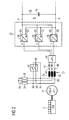
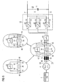
- FIG. 2 an equivalent circuit diagram of a first embodiment of a diesel-electric drive system according to the invention is shown schematically.
- the load-side self-commutated pulse-controlled converter 14 of the voltage intermediate-circuit converter 6 and the three-phase asynchronous motors 8 are as shown in FIGS FIG. 1 shown, not shown anymore.
- the AC-side terminals R, S and T of the generator-side self-commutated pulse converter 12 of the voltage source inverter 6 are each connected by means of a circuit breaker 40 with a stator-side terminal 42, 44 and 46 of the permanently excited synchronous generator 4 separable.
- the windings 78, 80 and 82 of its multi-phase stator winding system 74 are also shown by this permanent magnet synchronous generator 4. These windings 78, 80 and 82 are respectively connected on the one hand to the stator-side terminal 42, 44 and 46 and on the other hand to one of three braking resistors 34, 36 ° and 38 electrically conductive.
- the braking resistors 34, 36 and 38 of the polyphase brake resistor assembly are electrically connected in star in this illustration and correspond in value to the braking resistor 20 of the embodiment FIG. 1 ,
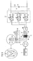
- These braking resistors 34, 36 and 38 of the multi-phase braking resistor arrangement can also be electrically connected in delta ( FIG. 3 ).
- connection point 86 and 88 by means of a switching device 32 with a connection point 84 is electrically conductively connected.
- the connection point of the switching device 32 which is electrically connected to the connection point 84, forms a lying outside of the permanently excited synchronous generator 4 star point 90.
- This star point 90 is shown in the generator mode by this multi-phase switching device 32, which is for example a bipolar disconnector, the de-energized with locked generator-side self-commutated converter 12 of the voltage source inverter 6 is switched.
- the flywheel voltage of this permanently excited synchronous generator 4 is too low. As a result, can be transferred from maximum diesel generator power at rated speed of the diesel engine 2 very quickly in the braking operation without the diesel engine 2 must be idle.
- switchable series connection of three braking resistors 34, 36 and 38 of the polyphase braking resistor arrangement with the windings 78, 80 and 82 of the multi-phase stator winding system 74 of the permanent magnet synchronous generator 4 with a voltage source inverter 6 can with the help of a bipolar, normally disconnected disconnector 32 between generator operation and brake operation are switched, whereby a high braking performance can be realized and the speed of the diesel engine can be set freely in braking mode.
- the generator-side self-commutated pulse-controlled converter 12 of the voltage intermediate-circuit converter 6 is realized in this embodiment of the diesel-electric drive system by means of converter bridge branch modules 48.
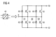
- An equivalent circuit diagram of a power converter bridge branch module 48 is shown in FIG FIG. 4 shown in more detail.
- the DC voltage side terminals 50 and 52 of each converter bridge branch module 48 of the generator side self-commutated pulse converter 12 are each electrically connected to a potential of the intermediate circuit 18 of the voltage source inverter 6.
- the DC-side connections 50 of the three converter bridge branch modules 48 of the self-commutated pulse-controlled converter 12 are each connected to a positive potential P of the intermediate circuit 18, whereas the DC-side connections 52 of these three converter bridge branch modules 48 are each associated with a negative potential N of the intermediate circuit 18.
- the power converter bridge branch module 48 has two bridge branch modules 54 that are electrically connected in parallel.
- Each bridge branch module 54 has two switchable semiconductor switches 56 and 58 connected electrically in series, in particular two insulated gate bipolar transistors (IGBT), which are each provided with a corresponding freewheeling diode 60 or 62.
- IGBT insulated gate bipolar transistors
- traction technology traction converters are constructed as modular as possible, with a bridge branch module 54 is used as the smallest unit.
- a power converter bridge branch module 48 for high performance.
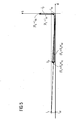
- FIG. 5 is in an orthogonal coordinate system d
- q is a phasor diagram, which applies to the braking operation at full braking power.
- the three braking resistors 34, 36 and 38 of the polyphase brake resistor assembly are each electrically connected in series with a winding 78, 80 and 82 of the multiphase stator winding system 74 of the permanent magnet synchronous generator 4.
- the permanently excited synchronous generator 4 is operated almost short-circuited, with a sufficient longitudinal inductance L d a continuous short-circuit current I sd not or only slightly exceeds the rated current.
- This continuous short-circuit current I sd flows through the series-connected braking resistors 34, 36 and 38, whereby the required braking power is dissipated. Due to the almost completely short-circuited permanently excited synchronous generator 4, a voltage U s present at the alternating-voltage side terminals R, S and T of the generator-side self-commutated pulse-controlled converter 12 of the voltage intermediate-circuit converter 6 is almost completely present at the terminals (connection points 84, 86, 88) of the braking resistors 34 , 36 and 38 to drive a braking current I s .
- the speed of the diesel engine 2 can be freely selected in braking mode.
- the iron losses of the permanently excited synchronous generator in braking mode are very low due to the field-weakening short-circuit current I sd .
- the drag losses corresponding to the rotational speed of the diesel engine 2 can be compensated by the permanently excited synchronous generator 4 with a low positive q-current component (torque-forming current I sq ). Thereby, the diesel engine 2 can run without fuel injection in the braking operation of the diesel-electric drive system.
- FIG. 6 a second embodiment of the diesel-electric drive system according to the invention is shown schematically.
- This embodiment differs from the embodiment according to FIG. 2 in that now the braking resistors 34, 36 and 38 of the multi-phase Bremswidestandsan Aunt are connected to the stator-side terminals 42, 44 and 46 of the permanent-magnet synchronous generator 4.
- a second terminal of a braking resistor 34, 36 and 38 thus forms an AC-side terminal 92, 94 and 96 of the permanent magnet synchronous generator 4, where by means of the polyphase circuit breaker 40, the AC-side terminals R, S and T of the generator-side self-commutated pulse converter 12 of capsstapnik- Inverter 6 are connected.
- the windings 78, 80 and 82 of the multiphase stator winding system 74 of the permanent magnet synchronous generator 4 are electrically connected in star in this embodiment by means of an internal star point 98.
- the braking resistors 34, 36 and 38 of the multi-phase braking resistor arrangement are each electrically bridgeable by means of a multi-phase switching device 32. That is, outside the braking operation of the diesel-electric drive system, these braking resistors 34, 36 and 38 are electrically short-circuited.
- the switching device 32 has a three-pole or two-pole isolator. In accordance with a required braking power and depending on a current I sd flowing in the permanently excited synchronous generator 4 during braking operation, the braking resistor 34 and 38 or 36 must be dimensioned.
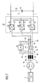
- FIG. 7 a third embodiment of the diesel-electric drive system according to the invention is illustrated.
- This embodiment differs from the embodiment according to FIG. 6 in that, instead of the polyphase switching device 32, the polyphase circuit breaker 40 is now used.
- This circuit breaker 40 thus assumes two tasks, namely the protection of the generator-side self-commutated pulse converter 12 of the voltage source inverter 6 in normal operation and braking operation and the function of three-phase short-circuiting of the braking resistors 34, 36 and 38.
- these three embodiments of the invention differ diesel-electric drive system according to the Figures 2 . 6 and 7 Not.
Landscapes
- Engineering & Computer Science (AREA)
- Power Engineering (AREA)
- Transportation (AREA)
- Mechanical Engineering (AREA)
- Life Sciences & Earth Sciences (AREA)
- Sustainable Development (AREA)
- Sustainable Energy (AREA)
- Control Of Eletrric Generators (AREA)
- Electric Propulsion And Braking For Vehicles (AREA)
- Stopping Of Electric Motors (AREA)
Claims (8)
- Système d'entraînement diesel électrique comprenant un générateur ( 4 ) synchrone à excitation permanente qui est couplé mécaniquement du côté du rotor à un moteur ( 2 ) diesel et qui est relié du côté du stator à un convertisseur ( 6 ) à circuit intermédiaire de tension, qui a du côté du générateur et du côté de la charge respectivement un convertisseur ( 12, 14 ) de courant à impulsion à commutation automatique, qui du côté tension continue sont combinés entre eux au moyen d'un circuit ( 18 ) intermédiaire de tension continue, et comprenant une résistance de frein, caractérisé en ce qu'il est prévu comme résistance de frein un agencement de résistance de frein polyphasé et que cet agencement de résistance de frein polyphasé peut être commuté au moyen d'un dispositif ( 32 ) de commutation polyphasé électriquement en série avec le système ( 74 ) polyphasé d'enroulement statorique du générateur ( 4 ) synchrone à excitation permanente.
- Système d'entraînement diesel électrique suivant la revendication 1, caractérisé en ce que respectivement un enroulement ( 78, 80, 82 ) du système ( 74 ) d'enroulement statorique polyphasé du générateur ( 4 ) synchrone à excitation permanente et une résistance ( 34, 36, 38 ) de frein de l'agencement de résistance de frein polyphasé peuvent être montés électriquement en série et en ce que le dispositif ( 32 ) de commutation polyphasé a deux séparateurs qui d'une part sont reliés respectivement par un point ( 86, 88 ) de liaison d'une résistance ( 34, 36 ) de frein à un enroulement ( 80, 82 ) du système ( 74 ) d'enroulement statorique polyphasé du générateur ( 4 ) synchrone à excitation permanente et d'autre part entre eux et en ce que ce point ( 90 ) commun de liaison des deux séparateurs est relié par un point ( 84 ) de liaison d'une résistance ( 38 ) de frein à un enroulement ( 78 ) du système ( 74 ) d'enroulement statorique polyphasé du générateur ( 4 ) synchrone à excitation permanente.
- Système d'entraînement diesel électrique suivant la revendication 1, caractérisé en ce que respectivement un enroulement ( 78, 80, 82 ) du système ( 74 ) d'enroulement statorique polyphasé du générateur ( 4 ) synchrone à excitation permanente est monté électriquement en série avec une résistance ( 34, 36, 38 ) de frein de l'agencement de résistance de frein polyphasé et en ce que le dispositif ( 32 ) de commutation polyphasé comporte trois dispositifs de court-circuit qui sont montés respectivement électriquement en parallèle avec une résistance ( 34, 36, 38 ) de frein de l'agencement de résistance de frein triphasé.
- Système d'entraînement diesel électrique suivant la revendication 1, caractérisé en ce que respectivement deux enroulements ( 78, 80, 82 ) du système ( 74 ) d'enroulement statorique polyphasé du générateur ( 4 ) synchrone à excitation permanente sont montés électriquement en série avec une résistance ( 34, 36, 38 ) de frein de l'agencement de résistance de frein polyphasé et en ce que le dispositif ( 32 ) de commutation polyphasé a deux dispositifs de court-circuit qui sont montés électriquement en parallèle avec une résistance ( 34, 36, 38 ) de frein de l'agencement de résistance de frein triphasé.
- Système d'entraînement diesel électrique suivant la revendication 1, caractérisé en ce qu'un enroulement ( 80 ) du système ( 74 ) d'enroulement statorique polyphasé du générateur ( 4 ) synchrone à excitation permanente est monté électriquement en série avec une résistance ( 36 ) de frein de l'agencement de résistance de frein polyphasé et en ce que le dispositif ( 32 ) de commutation comporte un dispositif de court-circuit qui est monté électriquement en parallèle avec cette résistance ( 36 ) de frein.
- Système d'entraînement diesel électrique suivant la revendication 1, caractérisé en ce que respectivement un enroulement (78, 80, 82 ) du système ( 74 ) d'enroulement statorique polyphasé du générateur ( 4 ) synchrone à excitation permanente est monté électriquement en série avec une résistance ( 34, 36, 38 ) de frein de l'agencement de résistance de frein polyphasé et en ce qu'un disjoncteur ( 40 ) polyphasé est monté électriquement en parallèle avec ces résistances ( 34, 36, 38 ) de frein.
- Système d'entraînement diesel électrique suivant la revendication 2, caractérisé en ce que les résistances ( 34, 36, 38 ) de frein de l'agencement de résistance de frein polyphasé sont montées en étoile.
- Système d'entraînement diesel électrique suivant la revendication 2, caractérisé en ce que les résistances ( 34, 36, 38 ) de frein de l'agencement de résistance de frein polyphasé sont montées électriquement en série.
Applications Claiming Priority (2)
| Application Number | Priority Date | Filing Date | Title |
|---|---|---|---|
| DE102006010537A DE102006010537B4 (de) | 2006-03-07 | 2006-03-07 | Dieselelektrisches Antriebssystem mit einem permanent erregten Synchrongenerator |
| PCT/EP2007/050729 WO2007101745A1 (fr) | 2006-03-07 | 2007-01-25 | Système d'entraînement diesel/électrique comprenant un générateur synchrone à excitation permanente |
Publications (2)
| Publication Number | Publication Date |
|---|---|
| EP1992063A1 EP1992063A1 (fr) | 2008-11-19 |
| EP1992063B1 true EP1992063B1 (fr) | 2011-10-12 |
Family
ID=37908190
Family Applications (1)
| Application Number | Title | Priority Date | Filing Date |
|---|---|---|---|
| EP07726230A Not-in-force EP1992063B1 (fr) | 2006-03-07 | 2007-01-25 | Système d'entraînement diesel/électrique comprenant un générateur synchrone à excitation permanente |
Country Status (8)
| Country | Link |
|---|---|
| US (1) | US20090072772A1 (fr) |
| EP (1) | EP1992063B1 (fr) |
| JP (1) | JP2009529308A (fr) |
| CN (1) | CN101395792A (fr) |
| AT (1) | ATE528849T1 (fr) |
| DE (1) | DE102006010537B4 (fr) |
| RU (1) | RU2414046C2 (fr) |
| WO (1) | WO2007101745A1 (fr) |
Families Citing this family (30)
| Publication number | Priority date | Publication date | Assignee | Title |
|---|---|---|---|---|
| DE102007003172B4 (de) * | 2006-08-08 | 2011-06-01 | Siemens Ag | Dieselelektrisches Antriebssystem |
| DE102007013050B4 (de) * | 2007-03-19 | 2011-05-12 | Siemens Ag | Fahrwerk für ein Schienenfahrzeug |
| DE102008023332B4 (de) * | 2008-05-13 | 2010-12-02 | Siemens Aktiengesellschaft | Dieselelektrisches Antriebssystem |
| DE102008028927A1 (de) * | 2008-06-18 | 2009-12-24 | Siemens Aktiengesellschaft | Vorrichtung zum Bremsen eines durch einen permanenterregten Synchronmotor angetriebenen Fahrzeuges |
| CN101718260B (zh) * | 2009-12-19 | 2011-07-27 | 山东鲁科风电设备有限公司 | 永磁直驱/半直驱风力发电机组自封闭刹车装置 |
| JP2011244557A (ja) * | 2010-05-17 | 2011-12-01 | Fuji Electric Co Ltd | 電力変換装置 |
| JP5611684B2 (ja) | 2010-06-22 | 2014-10-22 | 株式会社東芝 | 電力変換装置 |
| FR2963761B1 (fr) * | 2010-08-16 | 2014-02-28 | Alstom Transport Sa | Locomotive diesel-electrique |
| US8395335B2 (en) | 2010-08-20 | 2013-03-12 | Caterpillar Inc. | Method and system for eliminating fuel consumption during dynamic braking of electric drive machines |
| CN102126439B (zh) * | 2011-01-12 | 2012-10-03 | 枣庄学院 | 电动汽车能量回收系统 |
| US8857542B2 (en) | 2011-12-08 | 2014-10-14 | Caterpillar Inc. | Method and apparatus to eliminate fuel use for electric drive machines during trolley operation |
| JP6077131B2 (ja) | 2012-11-30 | 2017-02-08 | シーメンス アクティエンゲゼルシャフト | 障害除去時間を延長するための装置および方法 |
| US9515581B2 (en) * | 2012-12-13 | 2016-12-06 | Mitsubishi Electric Corporation | Motor control device |
| CN102991360B (zh) * | 2012-12-28 | 2015-12-23 | 上海三一重机有限公司 | 一种用于电驱动矿车的电制动控制方法 |
| CN103311918A (zh) * | 2013-05-23 | 2013-09-18 | 成都乾威科技有限公司 | 基于变频油机的直流发电系统 |
| FI125698B (fi) * | 2013-12-04 | 2016-01-15 | Konecranes Global Oy | Nostinkäyttö |
| JP2014161221A (ja) * | 2014-04-17 | 2014-09-04 | Fuji Electric Co Ltd | 電力変換装置 |
| CN105099239A (zh) * | 2014-05-06 | 2015-11-25 | 上海汽车集团股份有限公司 | 逆变器、汽车供电设备及汽车装置 |
| EP2992944A1 (fr) | 2014-09-03 | 2016-03-09 | Siemens Aktiengesellschaft | Procédé de réduction de l'humidité dans un boîtier |
| NL2013776B1 (en) * | 2014-11-11 | 2016-10-06 | Magnetic Innovations B V | Controllable electromagnetic brake system. |
| RU2597248C1 (ru) * | 2015-05-22 | 2016-09-10 | Федеральное государственное автономное образовательное учреждение высшего образования "Национальный исследовательский Томский политехнический университет" | Дизель-генераторная установка |
| PL3145042T3 (pl) * | 2015-09-16 | 2021-10-04 | We Tech Solutions Oy | Okrętowy zespół prądnicy wałowej |
| EP3223420B1 (fr) * | 2016-03-22 | 2020-05-06 | Siemens Aktiengesellschaft | Système de convertisseur de courant destiné au freinage fiable d'un système d'entrainement |
| RU168211U1 (ru) * | 2016-04-25 | 2017-01-24 | Сергей Викторович Байда | Транспортное средство (мотовоз) |
| RU2652286C1 (ru) * | 2017-05-29 | 2018-04-25 | федеральное государственное бюджетное образовательное учреждение высшего образования "Санкт-Петербургский горный университет" | Электроэнергетическая система морской буровой платформы |
| CN107910852B (zh) * | 2017-11-08 | 2019-10-11 | 上海金脉电子科技有限公司 | 车用电机转矩安全关断系统及其方法 |
| WO2019244193A1 (fr) * | 2018-06-18 | 2019-12-26 | 三菱電機株式会社 | Dispositif d'entraînement de moteur et climatiseur |
| ES1225959Y (es) | 2018-11-29 | 2019-05-28 | Grupos Electrogenos Europa S A U | Grupo electrogeno de velocidad variable |
| DE102021103023A1 (de) * | 2021-02-09 | 2022-08-11 | Schaeffler Technologies AG & Co. KG | Invertereinrichtung und elektrische Antriebsanordnung |
| WO2026067952A1 (fr) * | 2024-09-30 | 2026-04-02 | Vestas Wind Systems A/S | Extinction d'arc dans des éoliennes |
Family Cites Families (16)
| Publication number | Priority date | Publication date | Assignee | Title |
|---|---|---|---|---|
| US3568018A (en) * | 1969-06-06 | 1971-03-02 | Gen Motors Corp | Electric drive and brake arrangement and method |
| SU921023A1 (ru) * | 1980-07-01 | 1982-04-15 | Алтайский политехнический институт им.И.И.Ползунова | Устройство дл управлени торможением синхронного генератора |
| JPS59230477A (ja) * | 1983-06-13 | 1984-12-25 | Fuji Electric Co Ltd | 船用軸発電電動装置の電力消費装置 |
| US4720666A (en) * | 1986-06-03 | 1988-01-19 | Mitsubishi Denki Kabushiki Kaisha | Electric braking apparatus for brushless excitation system generator |
| EP0382867A1 (fr) * | 1989-02-15 | 1990-08-22 | Siemens Aktiengesellschaft | Appareil de commande des constantes de couple d'un moteur triphasé excité à aimant permanent |
| JPH05111109A (ja) * | 1991-10-08 | 1993-04-30 | Mitsubishi Heavy Ind Ltd | 内燃機関駆動電気式車両の制御方法 |
| RU2046492C1 (ru) * | 1993-12-09 | 1995-10-20 | Товарищество с ограниченной ответственностью "БЭЛ" | Устройство электрического торможения газотурбинной установки |
| JPH11332007A (ja) * | 1998-05-15 | 1999-11-30 | Isuzu Ceramics Res Inst Co Ltd | シリーズ型ハイブリッド自動車の駆動装置 |
| RU2139798C1 (ru) * | 1999-01-18 | 1999-10-20 | Открытое акционерное общество "Брянский машиностроительный завод" | Тяговый электропривод автономного транспортного средства |
| JP3489022B2 (ja) * | 1999-03-18 | 2004-01-19 | 株式会社安川電機 | ダイナミックブレーキ回路と半導体インバータ装置 |
| JP2001103794A (ja) * | 1999-09-28 | 2001-04-13 | Matsushita Seiko Co Ltd | 風力発電装置 |
| DE10103538B4 (de) * | 2001-01-26 | 2007-11-22 | Siemens Ag | Elektromotorisch angetriebenes Schienenfahrzeug mit Verbrennungsmotor |
| DE10136486C1 (de) * | 2001-07-27 | 2003-04-30 | Siemens Ag | Bremsvorrichtung |
| DE10160612A1 (de) * | 2001-12-11 | 2003-06-26 | Siemens Ag | Traktionsantrieb |
| DE10210164A1 (de) * | 2002-03-07 | 2003-09-18 | Michael Henschel | Vorrichtung zur mehrfachen Gleichrichterspeisung eines Synchrongenerators in einer Kraftanlage |
| GB0311013D0 (en) * | 2003-05-13 | 2003-06-18 | Newage Int Ltd | An electrical power generating system and a permanent magnet generator for such a system |
-
2006
- 2006-03-07 DE DE102006010537A patent/DE102006010537B4/de not_active Expired - Fee Related
-
2007
- 2007-01-25 EP EP07726230A patent/EP1992063B1/fr not_active Not-in-force
- 2007-01-25 JP JP2008557701A patent/JP2009529308A/ja active Pending
- 2007-01-25 AT AT07726230T patent/ATE528849T1/de active
- 2007-01-25 RU RU2008139630/07A patent/RU2414046C2/ru not_active IP Right Cessation
- 2007-01-25 US US12/282,002 patent/US20090072772A1/en not_active Abandoned
- 2007-01-25 WO PCT/EP2007/050729 patent/WO2007101745A1/fr not_active Ceased
- 2007-01-25 CN CNA2007800079524A patent/CN101395792A/zh active Pending
Also Published As
| Publication number | Publication date |
|---|---|
| JP2009529308A (ja) | 2009-08-13 |
| RU2008139630A (ru) | 2010-04-20 |
| RU2414046C2 (ru) | 2011-03-10 |
| DE102006010537B4 (de) | 2009-06-10 |
| ATE528849T1 (de) | 2011-10-15 |
| WO2007101745A1 (fr) | 2007-09-13 |
| DE102006010537A1 (de) | 2007-09-13 |
| CN101395792A (zh) | 2009-03-25 |
| EP1992063A1 (fr) | 2008-11-19 |
| US20090072772A1 (en) | 2009-03-19 |
Similar Documents
| Publication | Publication Date | Title |
|---|---|---|
| EP1992063B1 (fr) | Système d'entraînement diesel/électrique comprenant un générateur synchrone à excitation permanente | |
| WO2007101739A1 (fr) | Système d'entraînement diesel/électrique comprenant un générateur synchrone à excitation permanente | |
| DE102007003172B4 (de) | Dieselelektrisches Antriebssystem | |
| DE102008023332B4 (de) | Dieselelektrisches Antriebssystem | |
| WO2015128103A1 (fr) | Système d'entraînement électrique | |
| EP2088668A2 (fr) | Convertisseur statique | |
| EP2570291B1 (fr) | Système d'entraînement d'un véhicule fonctionnant sur batterie doté d'une machine synchrone à excitation permanente alimentée par convertisseur | |
| EP2570290B1 (fr) | Système d'entraînement d'un véhicule fonctionnant sur batterie doté d'une machine synchrone à excitation permanente alimentée par convertisseur | |
| DE102010025266A1 (de) | Transportfahrzeug mit einer Mehrzahl elektrischer Maschinen | |
| WO2015128101A1 (fr) | Système d'entraînement électrique | |
| DE102009046617A1 (de) | Wechselrichter | |
| EP2499729A2 (fr) | Onduleur avec circuit de calage de tension | |
| DE102009030727A1 (de) | Elektrischer Antrieb und Verfahren zum Betrieb eines elektrischen Antriebs | |
| DE19928106C1 (de) | Elektrisches Generator/Motor-System | |
| WO2015128104A1 (fr) | Système d'entraînement électrique | |
| DE102017201350B4 (de) | Verfahren zum Übertragen elektrischer Energie zwischen einem fahrzeugseitigen Energiespeicher und einer Anschlussstation sowie Fahrzeugbordnetz | |
| DE102005059760B4 (de) | Antriebssystem für ein Wasserfahrzeug | |
| DE3831126C2 (de) | Wechselrichter mit eingeprägter Zwischenkreisspannung | |
| DE102020126340A1 (de) | Wechselrichter für eine Antriebseinrichtung eines elektrisch antreibbaren Kraftfahrzeugs | |
| DE102020207856A1 (de) | Inverter für eine elektrische Maschine, elektrische Maschine mit solch einem Inverter sowie Lenksystem mit solch einer elektrischen Maschine | |
| DE102023212885A1 (de) | Elektrisches Antriebssystem für ein Fahrzeug | |
| DE102023103117A1 (de) | E-Maschine mit Wicklungsumschaltung und Verfahren zum Regeln des Betriebs einer solchen E-Maschine | |
| DE202011110669U1 (de) | Elektronischer Leistungswandler |
Legal Events
| Date | Code | Title | Description |
|---|---|---|---|
| PUAI | Public reference made under article 153(3) epc to a published international application that has entered the european phase |
Free format text: ORIGINAL CODE: 0009012 |
|
| 17P | Request for examination filed |
Effective date: 20080822 |
|
| AK | Designated contracting states |
Kind code of ref document: A1 Designated state(s): AT BE BG CH CY CZ DE DK EE ES FI FR GB GR HU IE IS IT LI LT LU LV MC NL PL PT RO SE SI SK TR |
|
| GRAP | Despatch of communication of intention to grant a patent |
Free format text: ORIGINAL CODE: EPIDOSNIGR1 |
|
| GRAS | Grant fee paid |
Free format text: ORIGINAL CODE: EPIDOSNIGR3 |
|
| GRAA | (expected) grant |
Free format text: ORIGINAL CODE: 0009210 |
|
| AK | Designated contracting states |
Kind code of ref document: B1 Designated state(s): AT BE BG CH CY CZ DE DK EE ES FI FR GB GR HU IE IS IT LI LT LU LV MC NL PL PT RO SE SI SK TR |
|
| REG | Reference to a national code |
Ref country code: GB Ref legal event code: FG4D Free format text: NOT ENGLISH |
|
| REG | Reference to a national code |
Ref country code: CH Ref legal event code: NV Representative=s name: SIEMENS SCHWEIZ AG Ref country code: CH Ref legal event code: EP |
|
| REG | Reference to a national code |
Ref country code: IE Ref legal event code: FG4D |
|
| REG | Reference to a national code |
Ref country code: DE Ref legal event code: R096 Ref document number: 502007008351 Country of ref document: DE Effective date: 20120112 |
|
| REG | Reference to a national code |
Ref country code: NL Ref legal event code: VDEP Effective date: 20111012 |
|
| LTIE | Lt: invalidation of european patent or patent extension |
Effective date: 20111012 |
|
| PG25 | Lapsed in a contracting state [announced via postgrant information from national office to epo] |
Ref country code: IS Free format text: LAPSE BECAUSE OF FAILURE TO SUBMIT A TRANSLATION OF THE DESCRIPTION OR TO PAY THE FEE WITHIN THE PRESCRIBED TIME-LIMIT Effective date: 20120212 Ref country code: LT Free format text: LAPSE BECAUSE OF FAILURE TO SUBMIT A TRANSLATION OF THE DESCRIPTION OR TO PAY THE FEE WITHIN THE PRESCRIBED TIME-LIMIT Effective date: 20111012 |
|
| PGFP | Annual fee paid to national office [announced via postgrant information from national office to epo] |
Ref country code: FR Payment date: 20120126 Year of fee payment: 6 |
|
| REG | Reference to a national code |
Ref country code: IE Ref legal event code: FD4D |
|
| PG25 | Lapsed in a contracting state [announced via postgrant information from national office to epo] |
Ref country code: GR Free format text: LAPSE BECAUSE OF FAILURE TO SUBMIT A TRANSLATION OF THE DESCRIPTION OR TO PAY THE FEE WITHIN THE PRESCRIBED TIME-LIMIT Effective date: 20120113 Ref country code: SE Free format text: LAPSE BECAUSE OF FAILURE TO SUBMIT A TRANSLATION OF THE DESCRIPTION OR TO PAY THE FEE WITHIN THE PRESCRIBED TIME-LIMIT Effective date: 20111012 Ref country code: SI Free format text: LAPSE BECAUSE OF FAILURE TO SUBMIT A TRANSLATION OF THE DESCRIPTION OR TO PAY THE FEE WITHIN THE PRESCRIBED TIME-LIMIT Effective date: 20111012 Ref country code: NL Free format text: LAPSE BECAUSE OF FAILURE TO SUBMIT A TRANSLATION OF THE DESCRIPTION OR TO PAY THE FEE WITHIN THE PRESCRIBED TIME-LIMIT Effective date: 20111012 Ref country code: PT Free format text: LAPSE BECAUSE OF FAILURE TO SUBMIT A TRANSLATION OF THE DESCRIPTION OR TO PAY THE FEE WITHIN THE PRESCRIBED TIME-LIMIT Effective date: 20120213 Ref country code: LV Free format text: LAPSE BECAUSE OF FAILURE TO SUBMIT A TRANSLATION OF THE DESCRIPTION OR TO PAY THE FEE WITHIN THE PRESCRIBED TIME-LIMIT Effective date: 20111012 |
|
| PGFP | Annual fee paid to national office [announced via postgrant information from national office to epo] |
Ref country code: DE Payment date: 20120319 Year of fee payment: 6 |
|
| PG25 | Lapsed in a contracting state [announced via postgrant information from national office to epo] |
Ref country code: CY Free format text: LAPSE BECAUSE OF FAILURE TO SUBMIT A TRANSLATION OF THE DESCRIPTION OR TO PAY THE FEE WITHIN THE PRESCRIBED TIME-LIMIT Effective date: 20111012 |
|
| PGFP | Annual fee paid to national office [announced via postgrant information from national office to epo] |
Ref country code: GB Payment date: 20120112 Year of fee payment: 6 |
|
| BERE | Be: lapsed |
Owner name: SIEMENS A.G. Effective date: 20120131 |
|
| PG25 | Lapsed in a contracting state [announced via postgrant information from national office to epo] |
Ref country code: IE Free format text: LAPSE BECAUSE OF FAILURE TO SUBMIT A TRANSLATION OF THE DESCRIPTION OR TO PAY THE FEE WITHIN THE PRESCRIBED TIME-LIMIT Effective date: 20111012 Ref country code: BG Free format text: LAPSE BECAUSE OF FAILURE TO SUBMIT A TRANSLATION OF THE DESCRIPTION OR TO PAY THE FEE WITHIN THE PRESCRIBED TIME-LIMIT Effective date: 20120112 Ref country code: SK Free format text: LAPSE BECAUSE OF FAILURE TO SUBMIT A TRANSLATION OF THE DESCRIPTION OR TO PAY THE FEE WITHIN THE PRESCRIBED TIME-LIMIT Effective date: 20111012 Ref country code: EE Free format text: LAPSE BECAUSE OF FAILURE TO SUBMIT A TRANSLATION OF THE DESCRIPTION OR TO PAY THE FEE WITHIN THE PRESCRIBED TIME-LIMIT Effective date: 20111012 Ref country code: DK Free format text: LAPSE BECAUSE OF FAILURE TO SUBMIT A TRANSLATION OF THE DESCRIPTION OR TO PAY THE FEE WITHIN THE PRESCRIBED TIME-LIMIT Effective date: 20111012 Ref country code: CZ Free format text: LAPSE BECAUSE OF FAILURE TO SUBMIT A TRANSLATION OF THE DESCRIPTION OR TO PAY THE FEE WITHIN THE PRESCRIBED TIME-LIMIT Effective date: 20111012 |
|
| PGFP | Annual fee paid to national office [announced via postgrant information from national office to epo] |
Ref country code: CH Payment date: 20120411 Year of fee payment: 6 |
|
| PLBE | No opposition filed within time limit |
Free format text: ORIGINAL CODE: 0009261 |
|
| STAA | Information on the status of an ep patent application or granted ep patent |
Free format text: STATUS: NO OPPOSITION FILED WITHIN TIME LIMIT |
|
| PG25 | Lapsed in a contracting state [announced via postgrant information from national office to epo] |
Ref country code: PL Free format text: LAPSE BECAUSE OF FAILURE TO SUBMIT A TRANSLATION OF THE DESCRIPTION OR TO PAY THE FEE WITHIN THE PRESCRIBED TIME-LIMIT Effective date: 20111012 Ref country code: IT Free format text: LAPSE BECAUSE OF FAILURE TO SUBMIT A TRANSLATION OF THE DESCRIPTION OR TO PAY THE FEE WITHIN THE PRESCRIBED TIME-LIMIT Effective date: 20111012 Ref country code: RO Free format text: LAPSE BECAUSE OF FAILURE TO SUBMIT A TRANSLATION OF THE DESCRIPTION OR TO PAY THE FEE WITHIN THE PRESCRIBED TIME-LIMIT Effective date: 20111012 Ref country code: MC Free format text: LAPSE BECAUSE OF NON-PAYMENT OF DUE FEES Effective date: 20120131 |
|
| 26N | No opposition filed |
Effective date: 20120713 |
|
| REG | Reference to a national code |
Ref country code: DE Ref legal event code: R097 Ref document number: 502007008351 Country of ref document: DE Effective date: 20120713 |
|
| PG25 | Lapsed in a contracting state [announced via postgrant information from national office to epo] |
Ref country code: BE Free format text: LAPSE BECAUSE OF NON-PAYMENT OF DUE FEES Effective date: 20120131 |
|
| PGFP | Annual fee paid to national office [announced via postgrant information from national office to epo] |
Ref country code: AT Payment date: 20111214 Year of fee payment: 6 |
|
| PG25 | Lapsed in a contracting state [announced via postgrant information from national office to epo] |
Ref country code: ES Free format text: LAPSE BECAUSE OF FAILURE TO SUBMIT A TRANSLATION OF THE DESCRIPTION OR TO PAY THE FEE WITHIN THE PRESCRIBED TIME-LIMIT Effective date: 20120123 |
|
| PG25 | Lapsed in a contracting state [announced via postgrant information from national office to epo] |
Ref country code: FI Free format text: LAPSE BECAUSE OF FAILURE TO SUBMIT A TRANSLATION OF THE DESCRIPTION OR TO PAY THE FEE WITHIN THE PRESCRIBED TIME-LIMIT Effective date: 20111012 |
|
| REG | Reference to a national code |
Ref country code: CH Ref legal event code: PL |
|
| REG | Reference to a national code |
Ref country code: AT Ref legal event code: MM01 Ref document number: 528849 Country of ref document: AT Kind code of ref document: T Effective date: 20130131 |
|
| GBPC | Gb: european patent ceased through non-payment of renewal fee |
Effective date: 20130125 |
|
| REG | Reference to a national code |
Ref country code: FR Ref legal event code: ST Effective date: 20130930 |
|
| PG25 | Lapsed in a contracting state [announced via postgrant information from national office to epo] |
Ref country code: LI Free format text: LAPSE BECAUSE OF NON-PAYMENT OF DUE FEES Effective date: 20130131 Ref country code: AT Free format text: LAPSE BECAUSE OF NON-PAYMENT OF DUE FEES Effective date: 20130131 Ref country code: DE Free format text: LAPSE BECAUSE OF NON-PAYMENT OF DUE FEES Effective date: 20130801 Ref country code: CH Free format text: LAPSE BECAUSE OF NON-PAYMENT OF DUE FEES Effective date: 20130131 |
|
| REG | Reference to a national code |
Ref country code: DE Ref legal event code: R119 Ref document number: 502007008351 Country of ref document: DE Effective date: 20130801 |
|
| PG25 | Lapsed in a contracting state [announced via postgrant information from national office to epo] |
Ref country code: FR Free format text: LAPSE BECAUSE OF NON-PAYMENT OF DUE FEES Effective date: 20130131 Ref country code: GB Free format text: LAPSE BECAUSE OF NON-PAYMENT OF DUE FEES Effective date: 20130125 |
|
| PG25 | Lapsed in a contracting state [announced via postgrant information from national office to epo] |
Ref country code: TR Free format text: LAPSE BECAUSE OF FAILURE TO SUBMIT A TRANSLATION OF THE DESCRIPTION OR TO PAY THE FEE WITHIN THE PRESCRIBED TIME-LIMIT Effective date: 20111012 |
|
| PG25 | Lapsed in a contracting state [announced via postgrant information from national office to epo] |
Ref country code: LU Free format text: LAPSE BECAUSE OF NON-PAYMENT OF DUE FEES Effective date: 20120125 |
|
| PG25 | Lapsed in a contracting state [announced via postgrant information from national office to epo] |
Ref country code: HU Free format text: LAPSE BECAUSE OF FAILURE TO SUBMIT A TRANSLATION OF THE DESCRIPTION OR TO PAY THE FEE WITHIN THE PRESCRIBED TIME-LIMIT Effective date: 20070125 |