EP1992553A2 - Kompaktfahrgestell für ein Motorrad mit Lufteinlass für integrierte Airbox - Google Patents
Kompaktfahrgestell für ein Motorrad mit Lufteinlass für integrierte Airbox Download PDFInfo
- Publication number
- EP1992553A2 EP1992553A2 EP08153543A EP08153543A EP1992553A2 EP 1992553 A2 EP1992553 A2 EP 1992553A2 EP 08153543 A EP08153543 A EP 08153543A EP 08153543 A EP08153543 A EP 08153543A EP 1992553 A2 EP1992553 A2 EP 1992553A2
- Authority
- EP
- European Patent Office
- Prior art keywords
- frame
- motorcycle
- box
- shaped body
- beams
- Prior art date
- Legal status (The legal status is an assumption and is not a legal conclusion. Google has not performed a legal analysis and makes no representation as to the accuracy of the status listed.)
- Withdrawn
Links
Images


Classifications
-
- B—PERFORMING OPERATIONS; TRANSPORTING
- B62—LAND VEHICLES FOR TRAVELLING OTHERWISE THAN ON RAILS
- B62J—CYCLE SADDLES OR SEATS; AUXILIARY DEVICES OR ACCESSORIES SPECIALLY ADAPTED TO CYCLES AND NOT OTHERWISE PROVIDED FOR, e.g. ARTICLE CARRIERS OR CYCLE PROTECTORS
- B62J37/00—Arrangements of fuel supply lines, taps, or the like, on motor cycles or engine-assisted cycles
-
- B—PERFORMING OPERATIONS; TRANSPORTING
- B62—LAND VEHICLES FOR TRAVELLING OTHERWISE THAN ON RAILS
- B62K—CYCLES; CYCLE FRAMES; CYCLE STEERING DEVICES; RIDER-OPERATED TERMINAL CONTROLS SPECIALLY ADAPTED FOR CYCLES; CYCLE AXLE SUSPENSIONS; CYCLE SIDECARS, FORECARS, OR THE LIKE
- B62K11/00—Motorcycles, engine-assisted cycles or motor scooters with one or two wheels
- B62K11/02—Frames
- B62K11/04—Frames characterised by the engine being between front and rear wheels
-
- B—PERFORMING OPERATIONS; TRANSPORTING
- B62—LAND VEHICLES FOR TRAVELLING OTHERWISE THAN ON RAILS
- B62K—CYCLES; CYCLE FRAMES; CYCLE STEERING DEVICES; RIDER-OPERATED TERMINAL CONTROLS SPECIALLY ADAPTED FOR CYCLES; CYCLE AXLE SUSPENSIONS; CYCLE SIDECARS, FORECARS, OR THE LIKE
- B62K19/00—Cycle frames
- B62K19/30—Frame parts shaped to receive other cycle parts or accessories
- B62K19/32—Steering heads
-
- F—MECHANICAL ENGINEERING; LIGHTING; HEATING; WEAPONS; BLASTING
- F02—COMBUSTION ENGINES; HOT-GAS OR COMBUSTION-PRODUCT ENGINE PLANTS
- F02M—SUPPLYING COMBUSTION ENGINES IN GENERAL WITH COMBUSTIBLE MIXTURES OR CONSTITUENTS THEREOF
- F02M35/00—Combustion-air cleaners, air intakes, intake silencers, or induction systems specially adapted for, or arranged on, internal-combustion engines
- F02M35/10—Air intakes; Induction systems
- F02M35/10006—Air intakes; Induction systems characterised by the position of elements of the air intake system in direction of the air intake flow, i.e. between ambient air inlet and supply to the combustion chamber
- F02M35/10026—Plenum chambers
- F02M35/10032—Plenum chambers specially shaped or arranged connecting duct between carburettor or air inlet duct and the plenum chamber; specially positioned carburettors or throttle bodies with respect to the plenum chamber
-
- F—MECHANICAL ENGINEERING; LIGHTING; HEATING; WEAPONS; BLASTING
- F02—COMBUSTION ENGINES; HOT-GAS OR COMBUSTION-PRODUCT ENGINE PLANTS
- F02M—SUPPLYING COMBUSTION ENGINES IN GENERAL WITH COMBUSTIBLE MIXTURES OR CONSTITUENTS THEREOF
- F02M35/00—Combustion-air cleaners, air intakes, intake silencers, or induction systems specially adapted for, or arranged on, internal-combustion engines
- F02M35/16—Combustion-air cleaners, air intakes, intake silencers, or induction systems specially adapted for, or arranged on, internal-combustion engines characterised by use in vehicles
- F02M35/162—Motorcycles; All-terrain vehicles, e.g. quads, snowmobiles; Small vehicles, e.g. forklifts
Definitions
- the present invention refers to a compact frame for a motorcycle with an air intake for the integrated airbox.
- the airbox is a device applied to the power supply unit of the motor and more specifically upstream of the carburettor or the air filter.
- Such a device has the function of increasing the pressure of the air going into the carburettor, creating a greater flow thereof with consequent supercharging of the motor.
- the airbox compared to previous technology that to obtain an improvement in performance exploited free intake, offers the advantage of preventing foreign objects from entering into the motor and limiting the intake noise.
- the air intakes have therefore been positioned firstly on the sides of the front cowl and then moved towards the centre thereof where the maximum pressure is ensured.
- a known type of compact frame that is widely used comprises die-cast beams in which the steering tube consists of an element still squashed permanently in a pack between the beams through screws arranged transversally with respect to the extension of the frame.
- the positioning of the air intakes in the front part of the motorcycles requires that special ducts be made, suitably arranged with respect to the frame, to take air to the airbox with negative consequences on the complexity, the costs and the production and assembly time of the motorcycles themselves.
- the purpose of the present invention is to avoid the aforementioned drawbacks and in particular to make a compact frame for motorcycles that makes the use of special ducts for taking air to the airbox superfluous.
- a further purpose of the present invention is to make a frame for motorcycles through which the costs and assembly times of the motorcycles can be reduced.
- Another purpose of the present invention is to provide a compact frame for motorcycles provided with air intake for the airbox.
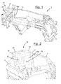
- a frame for motorcycles is shown, wholly indicated with 10,110,210.
- the frame 10,110,210 according to the invention comprises two beams 11,111,211 alternatively made in a single piece (monolithic frame) or fixedly connected together at a first rear end 12 of the frame 10,110,210 (frame with two body side panels), for example through transversal rods 13.
- the two beams 11,111,211 are also connected to a steering tube 20,120,220 for the passage of the tube of the fork (not depicted).
- the end portions 15 of the beams 11 at the front end 14 are flat and kept spaced apart so as to define an open seat.
- Such an open seat is suitable for housing the steering tube 20 that is locked between the two endings 15 through screws 17 arranged transversally to the main direction of extension of the frame 10.
- the top and bottom mouths of the steering tube 20 respectively face a top plate 21 and a bottom plate 22 fixedly connected to the tube 20 itself.
- the top and bottom plates 21 and 22 have a shape matching the section of the open seat made by the endings 15 of the beams 11.
- the four faces of such a box-shaped body 18 consist of the top plate 21, the bottom plate 22 and the endings 15 of the beams 11.
- Such a box-shaped body 18 surrounds the steering tube 20 and allows air to pass through the two opposite openings 16a,16b, in this way making the air intake for the airbox that is thus integrated in the frame 10.
- such endings 15 and the plates 21,22 have a plurality of holes suitable for receiving the screws 17.
- the steering tube 20 is fixedly connected in addition to at least one intermediate plate 23 that surrounds it.
- the endings 115 of the beams 111 at the front end 114 are arc-shaped and in particular U-shaped ( figures 3, 4 and 8 ) or C-shaped ( figures 6 and 7 ) according to the embodiment, and are arranged close together so that the ends of the projections are substantially in contact, so as to define in the frame 110 a through annular opening having its axis substantially longitudinal to the main extension of the frame 110.
- the resulting annular opening can have a cylindrical, oval or substantially rectangular section, for example with bevelled corners.
- the steering tube 120 is housed in a box-shaped body 118 having two opposite openings 116a,116b and with its axis substantially longitudinal to the main extension of the frame, and comes out into the top and bottom surfaces 121 and 122 thereof.
- Such a box-shaped body 118 has a coupling portion 124 that is preferably narrow, having a section matching the section of the annular opening defined by the endings 115 of the beams 111.
- the box-shaped body 118 can therefore be partially housed in said opening and squashed in a pack between such endings 115.
- Such screws 125 can be from ergal or else steel and equipped with bushings 126 made from aluminium according to the diagram depicted in figure 6 that foresees using such bushings 126 as a spigot on the second ending 115 and in order to make the screw 125 mounted on a blind hole of such a second portion 115 airtight.
- the box-shaped body 118 is locked at the endings 115 through a plurality of first screws 117 arranged longitudinally to the main direction of extension of the frame 110.
- the box-shaped body 118 at one 116a of said opposite openings 116a,116b, has a projecting flange 119 suitable for cooperating with the side of the endings 115 on the inside with respect to the frame 110.
- the flange 119 can be made in a single piece with the box-shaped body 118.
- the flange 119 can be mounted with slightly forced coupling on the box-shaped body 118 or else it can have the inner walls equipped with a draft angle so that, by means of the tightening of the screws 117, an elastic compression takes place on the end of the box-shaped body 118 that is suitably notched. In this way, the connection is tighter than it would be from a simple spigot.
- the flange 119 is provided with through holes suitable for receiving the screws 117. On the side of the endings 115 on the inside with respect to the frame 110 corresponding holes are also foreseen.
- the box-shaped body 118 and the endings 115 are configured and mutually arranged so as to leave free a seat for housing an ignition switch 130 as shown in figure 8 .
- the frame 110 can be made from magnesium.
- the screws 117 can be left in contact with the end portions 115 of the frame 110 in cases of coupling of steel material for the screws 117 and aluminium material for the frame 110, or aluminium material for the screws 117 and magnesium material for the frame 110, or else through the interposition of an aluminium flange 119 in the case of steel screws 117 and magnesium frame 110.
- a ring nut (not illustrated) can be used coupled with the coupling portion 124 of the box-shaped body 118.
- the annular opening formed by the endings 115 just like the coupling portion 124 of the box-shaped body 118, have a circular section.
- the centring and the radial positioning with respect to the axis of the opposite openings 116a,116b of the box-shaped body 118 is ensured through pins.
- the centring takes place directly in the narrow portion 124 of the box-shaped body 118 and the radial positioning must be achieved with a pin or an abutment plane.
- the ring nut may not be made from steel.
- the attachment therefore consists of a separate coupling portion 124, made from steel and having an external threading.
- the coupling portion 124 is partially screwed into the box-shaped body 118 and on the remaining part an aluminium ring nut is screwed that can be rested on magnesium. Box-shaped body 118 and ring nut are therefore screwed against one another on the steel coupling portion 124 safe against unscrewing.
- the beams 211 do not clamp a portion of the box-shaped body 218 into a pack at their endings 215, but they are locked at their end surface 224 to at least one joining element 219 foreseen on such a box-shaped body 218.
- box-shaped body 218 can also be fixedly connected to a monolithic frame.
- the endings 215 are arc-shaped.
- the box-shaped body 218, which contains the steering tube 220 has two opposite openings 216a,216b and with axis substantially longitudinal to the main extension of the frame.
- the steering tube 220 comes out into the top and bottom surfaces 221, 222 thereof.
- Such a box-shaped body 218 is locked to the endings 215 through a small number of screws 217, arranged longitudinally to the main direction of extension of the frame 210.
- the box-shaped body 218 is fixedly connected to the joining element 219 that cooperates with the side of the endings 215 that is outside with respect to the frame 210 and provided with a plurality of holes suitable for receiving the screws 217.
- washers 227 are foreseen at the holes.
- the endings 215 are also provided with corresponding through holes 225.
- each ending 215 comprises a pair of top holes 228a and a pair of bottom holes 228b suitably arranged and the joining element 219 comprises eight corresponding holes.
- the steering tube is sunk in a channel for the passage of air.
- the beams are no longer directly fixedly connected to the steering tube but locked to the box-shaped body. In this way, whilst not giving up compactness and robustness of the frame, an air intake is formed directly integrated in it.
Landscapes
- Engineering & Computer Science (AREA)
- Mechanical Engineering (AREA)
- Chemical & Material Sciences (AREA)
- Combustion & Propulsion (AREA)
- General Engineering & Computer Science (AREA)
- Automatic Cycles, And Cycles In General (AREA)
- Casings For Electric Apparatus (AREA)
Applications Claiming Priority (1)
| Application Number | Priority Date | Filing Date | Title |
|---|---|---|---|
| ITMI20070846 ITMI20070846A1 (it) | 2007-04-23 | 2007-04-23 | Telaio compatto per motoveicolo con presa d'aria per l'airbox integrata |
Publications (2)
| Publication Number | Publication Date |
|---|---|
| EP1992553A2 true EP1992553A2 (de) | 2008-11-19 |
| EP1992553A3 EP1992553A3 (de) | 2009-12-16 |
Family
ID=39800725
Family Applications (1)
| Application Number | Title | Priority Date | Filing Date |
|---|---|---|---|
| EP08153543A Withdrawn EP1992553A3 (de) | 2007-04-23 | 2008-03-28 | Kompaktfahrgestell für ein Motorrad mit Lufteinlass für integrierte Airbox |
Country Status (4)
| Country | Link |
|---|---|
| EP (1) | EP1992553A3 (de) |
| CN (1) | CN101293550A (de) |
| IT (1) | ITMI20070846A1 (de) |
| TW (1) | TW200900308A (de) |
Cited By (1)
| Publication number | Priority date | Publication date | Assignee | Title |
|---|---|---|---|---|
| JP2020084802A (ja) * | 2018-11-16 | 2020-06-04 | 本田技研工業株式会社 | 鞍乗り型車両 |
Families Citing this family (1)
| Publication number | Priority date | Publication date | Assignee | Title |
|---|---|---|---|---|
| CN108361130B (zh) * | 2018-01-26 | 2023-08-25 | 重庆隆鑫机车有限公司 | 高位进气的空滤系统及三轮车 |
Family Cites Families (5)
| Publication number | Priority date | Publication date | Assignee | Title |
|---|---|---|---|---|
| WO2003104071A1 (en) * | 2002-06-07 | 2003-12-18 | Brumby Corporation Limited | Motorcycle |
| JP4340500B2 (ja) * | 2003-09-09 | 2009-10-07 | 川崎重工業株式会社 | 自動二輪車の吸気装置 |
| JP4490143B2 (ja) * | 2004-03-23 | 2010-06-23 | 本田技研工業株式会社 | 車体フレーム構造 |
| JP4490203B2 (ja) * | 2004-08-09 | 2010-06-23 | 川崎重工業株式会社 | 自動二輪車の吸気装置 |
| JP2007062643A (ja) * | 2005-09-01 | 2007-03-15 | Yamaha Motor Co Ltd | 自動二輪車の車体冷却構造および自動二輪車 |
-
2007
- 2007-04-23 IT ITMI20070846 patent/ITMI20070846A1/it unknown
-
2008
- 2008-03-28 EP EP08153543A patent/EP1992553A3/de not_active Withdrawn
- 2008-04-21 TW TW097114403A patent/TW200900308A/zh unknown
- 2008-04-23 CN CNA2008100954692A patent/CN101293550A/zh active Pending
Cited By (1)
| Publication number | Priority date | Publication date | Assignee | Title |
|---|---|---|---|---|
| JP2020084802A (ja) * | 2018-11-16 | 2020-06-04 | 本田技研工業株式会社 | 鞍乗り型車両 |
Also Published As
| Publication number | Publication date |
|---|---|
| CN101293550A (zh) | 2008-10-29 |
| TW200900308A (en) | 2009-01-01 |
| ITMI20070846A1 (it) | 2008-10-24 |
| EP1992553A3 (de) | 2009-12-16 |
Similar Documents
| Publication | Publication Date | Title |
|---|---|---|
| JP4333747B2 (ja) | 車両用内燃機関の吸気装置 | |
| US8146699B2 (en) | Motorcycle | |
| JP2001090622A (ja) | 車両用エンジンの吸気装置 | |
| US9975586B2 (en) | Rear structure of motorcycle | |
| EP1992553A2 (de) | Kompaktfahrgestell für ein Motorrad mit Lufteinlass für integrierte Airbox | |
| JP4333985B2 (ja) | スクータ型自動二輪車 | |
| US20160040637A1 (en) | Air intake device for motorcycle | |
| JP4939392B2 (ja) | エンジンの吸気通路構造 | |
| EP4628373A3 (de) | Zweirädriges fahrzeug | |
| JP2010265870A (ja) | インテークマニホールド | |
| BRPI0910114B1 (pt) | estrutura de montagem de dispositivo de injeção de combustível | |
| CN219172361U (zh) | 雨刮连接结构 | |
| CN211685352U (zh) | 一种型材端口封头结构及车用型材 | |
| JP2008542117A (ja) | 自動二輪車の荷物収納容器 | |
| JP2004301014A (ja) | エンジンの吸気構造 | |
| JP6767900B2 (ja) | 吸気マニホールド装置 | |
| EP1995164A2 (de) | Fahrgestell für ein Motorrad mit einstellbarem Nachlauf | |
| JP3109124B2 (ja) | 自動2輪車のエアクリーナ装置 | |
| CN216580826U (zh) | 一种自行车车头及自行车 | |
| JP6173094B2 (ja) | 内燃機関用吸気マニホールド | |
| KR102229704B1 (ko) | 경고등이 장착되는 차선규제봉 | |
| CN222949967U (zh) | 一种带进气歧管的摩托车节气门总成 | |
| JPH0585999U (ja) | 門用型材連結装置 | |
| CN211640798U (zh) | 一种空气流量计加工模具 | |
| CN211045540U (zh) | 模组连接板、模组安装组件及电池包 |
Legal Events
| Date | Code | Title | Description |
|---|---|---|---|
| PUAI | Public reference made under article 153(3) epc to a published international application that has entered the european phase |
Free format text: ORIGINAL CODE: 0009012 |
|
| AK | Designated contracting states |
Kind code of ref document: A2 Designated state(s): AT BE BG CH CY CZ DE DK EE ES FI FR GB GR HR HU IE IS IT LI LT LU LV MC MT NL NO PL PT RO SE SI SK TR |
|
| AX | Request for extension of the european patent |
Extension state: AL BA MK RS |
|
| PUAL | Search report despatched |
Free format text: ORIGINAL CODE: 0009013 |
|
| AK | Designated contracting states |
Kind code of ref document: A3 Designated state(s): AT BE BG CH CY CZ DE DK EE ES FI FR GB GR HR HU IE IS IT LI LT LU LV MC MT NL NO PL PT RO SE SI SK TR |
|
| AX | Request for extension of the european patent |
Extension state: AL BA MK RS |
|
| 17P | Request for examination filed |
Effective date: 20100507 |
|
| 17Q | First examination report despatched |
Effective date: 20100601 |
|
| AKX | Designation fees paid |
Designated state(s): AT BE BG CH CY CZ DE DK EE ES FI FR GB GR HR HU IE IS IT LI LT LU LV MC MT NL NO PL PT RO SE SI SK TR |
|
| STAA | Information on the status of an ep patent application or granted ep patent |
Free format text: STATUS: THE APPLICATION IS DEEMED TO BE WITHDRAWN |
|
| 18D | Application deemed to be withdrawn |
Effective date: 20101012 |