EP1992879A1 - Four de cuisson, en particulier four de cuisson domestique - Google Patents
Four de cuisson, en particulier four de cuisson domestique Download PDFInfo
- Publication number
- EP1992879A1 EP1992879A1 EP07009765A EP07009765A EP1992879A1 EP 1992879 A1 EP1992879 A1 EP 1992879A1 EP 07009765 A EP07009765 A EP 07009765A EP 07009765 A EP07009765 A EP 07009765A EP 1992879 A1 EP1992879 A1 EP 1992879A1
- Authority
- EP
- European Patent Office
- Prior art keywords
- cooking oven
- cavity
- fan
- oven according
- air
- Prior art date
- Legal status (The legal status is an assumption and is not a legal conclusion. Google has not performed a legal analysis and makes no representation as to the accuracy of the status listed.)
- Withdrawn
Links
- 238000010411 cooking Methods 0.000 title claims abstract description 35
- 238000010438 heat treatment Methods 0.000 claims description 10
- 230000000694 effects Effects 0.000 description 3
- 239000000654 additive Substances 0.000 description 2
- 230000000996 additive effect Effects 0.000 description 2
- 239000002184 metal Substances 0.000 description 2
- 238000000034 method Methods 0.000 description 1
- 230000005855 radiation Effects 0.000 description 1
- 230000001105 regulatory effect Effects 0.000 description 1
Images


Classifications
-
- F—MECHANICAL ENGINEERING; LIGHTING; HEATING; WEAPONS; BLASTING
- F24—HEATING; RANGES; VENTILATING
- F24C—DOMESTIC STOVES OR RANGES ; DETAILS OF DOMESTIC STOVES OR RANGES, OF GENERAL APPLICATION
- F24C15/00—Details
- F24C15/32—Arrangements of ducts for hot gases, e.g. in or around baking ovens
- F24C15/322—Arrangements of ducts for hot gases, e.g. in or around baking ovens with forced circulation
- F24C15/325—Arrangements of ducts for hot gases, e.g. in or around baking ovens with forced circulation electrically-heated
Definitions
- the invention relates to a cooking oven, especially to a domestic cooking oven, with a heatable cavity, wherein a fan having a rotating fan wheel is arranged in or adjacent to the cavity, wherein a first fluidic connection is arranged between at least one air input opening of the cavity and the fan and wherein at least one second fluidic connection is arranged between an air output opening of the fan and the cavity.
- Ovens of this kind are well-known in the art.
- the dish to be cooked in the oven is exposed to hot air which is transported by a fan.
- Most of today's hot air systems in ovens generate a three-dimensional air flow inside the cavity of the oven.
- a plurality of trays e. g. baking trays
- the fan wheel blows air out not perfectly radial but at an angel. This situation is shown in FIG 2 and depicted by the arrows extending away from the fan wheel 4. Furthermore, the air blown to the top and bottom is forced to the side outlet openings which lead to a higher air volume flow in the upper and lower corners. Due to the two effects the air volume flow distribution at the outlet of a usual fan cover 27 becomes inhomogeneous as shown by the air distribution 26 in FIG 2 . This influences also the air flow pattern over the different baking trays placed in the cavity of the oven.
- the inlet of such a fan is also problematic because a rotation of the air that is sucked in the fan is also generated.
- FIG 3 for a conventional solution showing the air flow in front of the fan less air is sucked in from the upper and lower regions of the cavity if the fan wheel 4 is mounted in the centre as it is depicted by the arrows.
- the solution of this object according to the invention is characterized in that at least one cover element is arranged which forms a wall for the air blown by the fan along the second fluidic connection, wherein the cover element extends substantially along the entire height of the cavity and wherein the cover element is formed to establish a substantial uniform air flow along substantial the entire height of the cover element.
- the cover element extends along at least 80 % of the height of the cavity.
- the fan is normally arranged in the rear part of the cavity, opposite to a front door of the oven.
- the axis of rotation of the fan wheel is usually arranged horizontally and from the rear side to the front side of the cavity.
- the cover element according to the invention has - according to a first concept - a first section extending substantial parallel to the backside of the cavity and has a second section wherein the distance between the cover element and the backside of the cavity becomes smaller in the second section when moving away from the fan.
- a noz-zle-like design is created by the fan cover.
- the first section is preferably adjacent to the fan while the second section is remote from the fan.
- the cover element can have different distances from the backside of the cavity along its height in a vertical section at at least one location of the second fluidic connection.
- a kind of air regulator is achieved to obtain a desired distribution of air flow in vertical direction.
- the cover element, especially its second section can have a smaller distance from the backside of the cavity in the upper and lower region than in the middle region.
- the distance from the backside of the cavity is symmetrically in the upper and lower region relatively to the middle region.
- the cover element having a plurality of air guiding channels which are arranged horizontally and are formed by at least two guiding ribs arranged at or on the cover element.
- the guiding ribs can have a length which is between 2 times and 4 times of the distance of the guiding ribs, especially three times as long.
- the length of the guiding ribs can alter in vertical direction, to achieve an air regulation effect.
- the length of the guiding ribs can be longer in the upper and in the lower region than in the middle region.
- Another feature of the invention is characterized in that a cover plate is arranged in front of the input opening of the fan, wherein the cover plate has a plurality of openings for the entry of air.
- the cover plate can have a homogeneous distribution of openings; the openings in the cover plate can have a round shape and can be equal in diameter.
- the cover plate can also have a non-homogeneous distribution of openings; the openings in the cover plate can have a round shape and can have at least partially different diameters.
- a further embodiment of the invention has a heating element which is arranged in front of the fan.
- the heating element can be arranged between the cover plate and the fan. It is preferably ring-shaped.
- the fan cover of the invention has thus outlet openings with a characteristic geometry. It spans almost the whole height of the cavity to provide all levels where trays can be inserted with the same or approximately the same air volume flow.
- the channel from the fan wheel to the outlet narrows like a nozzle which increases the flow resistance and herewith the pressure drop and levels out the inhomogeneous pressure profile and air speed profile generated by the fan to a certain degree.
- the mentioned air regulators can be inserted in addition to the usage of a nozzle or replacing it.
- the mentioned channels can be employed. Their length can be about three times their width and they can be combined with the air regulator principle, because longer channels and guiding ribs respectively give a higher flow resistance as does a smaller opening area. Those channels and ribs respectively can further work as a "circulation divider" to get rid of the rotation of the air inside the cavity which is caused by the non-perpendicular exiting direction of the air from the fan cover. Additionally guiding vanes can be placed inside the cavity and/or mounted at the tray supports which have the same circulation divider effect and help to generate the desired two-dimensional air flow pattern.
- the inlet is made to deal with the mentioned problems of the rotation of the air sucked in and the differing air speed (volume flow) over the height of the cavity.
- a cover plate can thus put in front of the inlet opening of the fan which flattens the low pressure profile at the inlet by increasing flow resistance and reshapes the inlet from a hole to two slits which prevents the rotating of the air to a certain degree. Further, this inlet cover levels out the pressure difference between the trays on the different levels and the inlet opening. By this way almost the same amount of air is sucked in on every level. Additionally air regulators and/or channels as described above can be used to further modify the air flow.
- the inlet cover can be extended over the whole back of the cavity and be punctured with holes which could be distributed in a specific way and/or have specific different sizes to create any intended air inlet profile (distribution of entering volume flow over the cover area).
- the ring shaped heating element could be placed not only around the fan as know in the prior art, but also in front of the fan in the sucking channel. This has the advantage that the heated air is mixed up while pressed through the fan wheel and therefore the air temperature distribution over the outlet opening is more even. For this alternative it is crucial where the holes are put in the inlet cover because the inlet cover has to block the food from the direct radiation coming from the heating element.
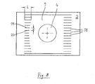
- FIG 1 shows the general design of a cooking oven 1, specifically of a domestic cooking oven, having a cavity 2.
- the cavity 2 is closed at the front of the oven 1 by a door 10.
- a fan 3 is arranged, having a fan wheel 4 which rotates around an axis 11 of rotation.
- a plurality of trays 24 can be'inserted into the cavity 2, which are arranged on top of each other.
- FIG 4 and FIG 5 a cover element 9 is shown which improves the homogeneity of the air flow created by the operation of the fan 3.
- the fan 3 with its rotating fan wheel 4 is arranged adjacent to the backside 13 of the cavity 2 and sucks in air from the cavity 2 from an air input opening 6 via a first fluidic connection 5 (see FIG 5 ).
- the air is transported by the fan wheel 4 and is blown out to an air output opening 8 (or more specific: to two output openings 8) via a second fluidic connection 7.
- first fluidic connection 5 is arranged between the air input opening 6 of the cavity 2 and the fan 3 and the second fluidic connection 7 is arranged between an air output opening 8 of the fan 3 and the cavity 2. This is depicted in FIG 5 by the lines with the arrows.
- a cover element 9 is arranged which forms a wall for the air blown by the fan 3 along the second fluidic connection 7.
- the cover element 9 extends substantially along the entire height of the cavity 2, see FIG 4 .
- the cover element 9 is formed to establish a substantial uniform air flow along substantial the entire height of the cover element 2.
- the distance D (see FIG 5 ) between the backside 13 and the cover element 9 measured in horizontal direction and along an axis between the front door 10 and the backside 13 of the cavity 2 becomes smaller when moving away from the fan 3.
- a nozzle-like design is created which improves the homogeneity of the air flow.
- the air is blown out by the fan 3 at the air output opening 8 of the cover element 9.
- the air regulator 25 is basically a sheet metal element which creates an altering distance d between the cover element 9 and the backside 13 of the cavity 2 with respect to the vertical height.
- the distance d is a maximum in a middle region 17 of the cavity 2 and becomes smaller in an upper region 15 and lower region 16.
- the air flow can be influenced by choosing the run of the distance d along the height of the cavity 2.
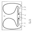
- FIG 8 Another alternative or additive possibility to homogenise and to influence the air flow from the fan 3 into the cavity 2 is shown in FIG 8 .
- a plurality of air guiding channels 18 is arranged on the sheet metal of the cover element 9.
- the air guiding channels 18 are formed by two adjacent guiding ribs 19, 20 which are arranged at a vertical distance x.
- the length L of the ribs 19, 20 is about three times of the distance x.
- the length L of the ribs 19, 20 can also alter along the vertical height of the cover element 9, as shown in the left part of FIG 8 .
- the longer the ribs 19, 20 are the higher is the flow resistance which is exerted onto the air flowing through the air guiding channels 18.
- a regulation of the air flow can occur by choosing the right length L of the ribs 19, 20.
- FIG 9 and FIG 10 another possibility is shown by which the air flow can be homogenised.
- a cover plate 21 is arranged in front of the fan 3.
- the cover plate 21 has a plurality of openings 22, preferably bores, which can have the same diameter or different diameters.
- openings 22 are shown which have different diameters, i. e. several classes of diameters.
- FIG 11 a cover plate 21 is shown which has a substantial homogeneous distribution of openings 22 with the same diameter but leaves a certain field with no bores in the middle part of the cover plate 21, behind which the ring-shaped fan is arranged.
- FIG 11 and FIG 12 another feature is depicted which is beneficially.
- a heating element 23 with a circular shape is placed between the cover plate 21 and the fan wheel 4. So, the air sucked into the fan 3 is heated up. The heat introduced by the heating element 23 into the air is homogeneously distributed in the air when it leaves the cover element 9 at both sides.
- FIG 13 a top plan view is depicted which shows schematically the flow pattern in one certain level of height in the cavity 2. Due to the pre-described provisions an evenly distributed air flow is guaranteed which is substantial equal on all tray levels.
Landscapes
- Engineering & Computer Science (AREA)
- Chemical & Material Sciences (AREA)
- Combustion & Propulsion (AREA)
- Mechanical Engineering (AREA)
- General Engineering & Computer Science (AREA)
- Baking, Grill, Roasting (AREA)
Priority Applications (1)
| Application Number | Priority Date | Filing Date | Title |
|---|---|---|---|
| EP07009765A EP1992879A1 (fr) | 2007-05-16 | 2007-05-16 | Four de cuisson, en particulier four de cuisson domestique |
Applications Claiming Priority (1)
| Application Number | Priority Date | Filing Date | Title |
|---|---|---|---|
| EP07009765A EP1992879A1 (fr) | 2007-05-16 | 2007-05-16 | Four de cuisson, en particulier four de cuisson domestique |
Publications (1)
| Publication Number | Publication Date |
|---|---|
| EP1992879A1 true EP1992879A1 (fr) | 2008-11-19 |
Family
ID=38606625
Family Applications (1)
| Application Number | Title | Priority Date | Filing Date |
|---|---|---|---|
| EP07009765A Withdrawn EP1992879A1 (fr) | 2007-05-16 | 2007-05-16 | Four de cuisson, en particulier four de cuisson domestique |
Country Status (1)
| Country | Link |
|---|---|
| EP (1) | EP1992879A1 (fr) |
Cited By (9)
| Publication number | Priority date | Publication date | Assignee | Title |
|---|---|---|---|---|
| WO2013173204A1 (fr) * | 2012-05-17 | 2013-11-21 | Illinois Tool Works Inc. | Plaque à jet pour la régulation d'un écoulement d'air dans un four |
| EP2735806A1 (fr) * | 2012-11-21 | 2014-05-28 | Manitowoc Foodservice Companies, LLC | Four de cuisson et procédé avec diffuseur d'air amovible |
| IT201700002764A1 (it) * | 2017-01-12 | 2018-07-12 | Tecnoeka S R L | Forno per la cottura di alimenti |
| US10088172B2 (en) | 2016-07-29 | 2018-10-02 | Alto-Shaam, Inc. | Oven using structured air |
| EP4125512A4 (fr) * | 2020-04-02 | 2024-07-31 | Automation Tech, LLC | Appareil de cuisson modulaire doté d'un four à air chaud |
| US12178357B2 (en) | 2020-04-02 | 2024-12-31 | Automation Tech, LLC | Modular cooking appliance |
| US12239255B2 (en) | 2020-04-02 | 2025-03-04 | Automation Tech, LLC | Modular cooking appliance |
| US12287098B2 (en) | 2020-04-02 | 2025-04-29 | Automation Tech, LLC | Modular cooking appliance having a grease shield |
| US12480662B2 (en) | 2020-04-02 | 2025-11-25 | Automation Tech, LLC | Modular cooking appliance having a user interface |
Citations (10)
| Publication number | Priority date | Publication date | Assignee | Title |
|---|---|---|---|---|
| GB2109920A (en) | 1981-10-02 | 1983-06-08 | Victoria Gas & Fuel Corp | Forced draught ovens |
| EP0084006A1 (fr) | 1982-01-06 | 1983-07-20 | DE DIETRICH & Cie, Société dite | Four électrique de cuisson domestique |
| EP0105931A1 (fr) | 1982-04-14 | 1984-04-25 | Matsushita Electric Industrial Co., Ltd. | Dispositif de cuisson du type a circulation d'air chaud |
| EP0245618A2 (fr) * | 1986-05-15 | 1987-11-19 | Kabushiki Kaisha Toshiba | Cuisinière à air circulé |
| GB2286455A (en) | 1994-02-10 | 1995-08-16 | Stoves Ltd | Gaseous fuel burner assemblies |
| DE4413252A1 (de) | 1994-04-16 | 1995-10-19 | Licentia Gmbh | Elektrischer Back- und Bratofen |
| EP1624255A1 (fr) * | 2004-08-04 | 2006-02-08 | Samsung Electronics Co., Ltd. | Procédé et dispositif pour maintenir la température dans un compartiment d'un four |
| EP1707884A2 (fr) | 2005-03-31 | 2006-10-04 | Lg Electronics Inc. | Appareil de cuisson |
| WO2007020587A1 (fr) | 2005-08-12 | 2007-02-22 | Arcelik Anonim Sirketi | Dispositif de cuisson |
| WO2007020584A1 (fr) | 2005-08-12 | 2007-02-22 | Arcelik Anonim Sirketi | Dispositif de cuisson |
-
2007
- 2007-05-16 EP EP07009765A patent/EP1992879A1/fr not_active Withdrawn
Patent Citations (10)
| Publication number | Priority date | Publication date | Assignee | Title |
|---|---|---|---|---|
| GB2109920A (en) | 1981-10-02 | 1983-06-08 | Victoria Gas & Fuel Corp | Forced draught ovens |
| EP0084006A1 (fr) | 1982-01-06 | 1983-07-20 | DE DIETRICH & Cie, Société dite | Four électrique de cuisson domestique |
| EP0105931A1 (fr) | 1982-04-14 | 1984-04-25 | Matsushita Electric Industrial Co., Ltd. | Dispositif de cuisson du type a circulation d'air chaud |
| EP0245618A2 (fr) * | 1986-05-15 | 1987-11-19 | Kabushiki Kaisha Toshiba | Cuisinière à air circulé |
| GB2286455A (en) | 1994-02-10 | 1995-08-16 | Stoves Ltd | Gaseous fuel burner assemblies |
| DE4413252A1 (de) | 1994-04-16 | 1995-10-19 | Licentia Gmbh | Elektrischer Back- und Bratofen |
| EP1624255A1 (fr) * | 2004-08-04 | 2006-02-08 | Samsung Electronics Co., Ltd. | Procédé et dispositif pour maintenir la température dans un compartiment d'un four |
| EP1707884A2 (fr) | 2005-03-31 | 2006-10-04 | Lg Electronics Inc. | Appareil de cuisson |
| WO2007020587A1 (fr) | 2005-08-12 | 2007-02-22 | Arcelik Anonim Sirketi | Dispositif de cuisson |
| WO2007020584A1 (fr) | 2005-08-12 | 2007-02-22 | Arcelik Anonim Sirketi | Dispositif de cuisson |
Cited By (13)
| Publication number | Priority date | Publication date | Assignee | Title |
|---|---|---|---|---|
| WO2013173204A1 (fr) * | 2012-05-17 | 2013-11-21 | Illinois Tool Works Inc. | Plaque à jet pour la régulation d'un écoulement d'air dans un four |
| US9303879B2 (en) | 2012-05-17 | 2016-04-05 | Illinois Tool Works Inc. | Jet plate for airflow control in an oven |
| EP2735806A1 (fr) * | 2012-11-21 | 2014-05-28 | Manitowoc Foodservice Companies, LLC | Four de cuisson et procédé avec diffuseur d'air amovible |
| RU2569252C2 (ru) * | 2012-11-21 | 2015-11-20 | Манитовок Фудсервис Компаниз, Ллк | Кулинарная печь со съемной вентиляционной решеткой и способ ее эксплуатации |
| US9618213B2 (en) | 2012-11-21 | 2017-04-11 | Manitowoc Foodservice Companies, Llc | Cooking oven and method with removable air diffuser |
| US10088172B2 (en) | 2016-07-29 | 2018-10-02 | Alto-Shaam, Inc. | Oven using structured air |
| EP3348914A1 (fr) * | 2017-01-12 | 2018-07-18 | Tecnoeka S.R.L. | Four pour cuire des aliments |
| IT201700002764A1 (it) * | 2017-01-12 | 2018-07-12 | Tecnoeka S R L | Forno per la cottura di alimenti |
| EP4125512A4 (fr) * | 2020-04-02 | 2024-07-31 | Automation Tech, LLC | Appareil de cuisson modulaire doté d'un four à air chaud |
| US12178357B2 (en) | 2020-04-02 | 2024-12-31 | Automation Tech, LLC | Modular cooking appliance |
| US12239255B2 (en) | 2020-04-02 | 2025-03-04 | Automation Tech, LLC | Modular cooking appliance |
| US12287098B2 (en) | 2020-04-02 | 2025-04-29 | Automation Tech, LLC | Modular cooking appliance having a grease shield |
| US12480662B2 (en) | 2020-04-02 | 2025-11-25 | Automation Tech, LLC | Modular cooking appliance having a user interface |
Similar Documents
| Publication | Publication Date | Title |
|---|---|---|
| EP1992879A1 (fr) | Four de cuisson, en particulier four de cuisson domestique | |
| US8461488B2 (en) | Oven | |
| US5601070A (en) | Convection oven | |
| US20130284161A1 (en) | Oven appliance with features for selecting convection air flow direction | |
| KR100876463B1 (ko) | 오븐 | |
| EP1793171A1 (fr) | Dispositif de cuisson par chauffage | |
| JP2018179381A (ja) | 加熱調理器 | |
| KR101207641B1 (ko) | 가열조리기 | |
| CN113143053A (zh) | 烹饪设备 | |
| US20080045136A1 (en) | Multiple Air dam device | |
| US6689991B2 (en) | Electronic range | |
| US11849527B2 (en) | Oven appliance with improved convection cooking performance | |
| KR100672475B1 (ko) | 멀티 덕트 컨벡션 오븐 레인지 | |
| JP4791983B2 (ja) | 加熱調理器 | |
| EP2060854B1 (fr) | Four de cuisson avec ensemble de chauffage amélioré | |
| JP5377133B2 (ja) | 加熱調理器 | |
| JP5377132B2 (ja) | 加熱調理器 | |
| ITTO20080296A1 (it) | Forno ventilato | |
| KR100727875B1 (ko) | 오븐렌지 | |
| CN117017081B (zh) | 一种烹饪装置及烹饪一体机和集成灶 | |
| EP1739362A2 (fr) | Four ménager avec système de circulation d'air | |
| JPH06103100B2 (ja) | 熱風循環式調理器 | |
| EP3253216B1 (fr) | Appareil de cuisson | |
| US20250176758A1 (en) | Air outlet structure for air fryer | |
| ITUB20152807A1 (it) | Ventola per forni per la cottura di alimenti |
Legal Events
| Date | Code | Title | Description |
|---|---|---|---|
| PUAI | Public reference made under article 153(3) epc to a published international application that has entered the european phase |
Free format text: ORIGINAL CODE: 0009012 |
|
| 17P | Request for examination filed |
Effective date: 20080514 |
|
| AK | Designated contracting states |
Kind code of ref document: A1 Designated state(s): AT BE BG CH CY CZ DE DK EE ES FI FR GB GR HU IE IS IT LI LT LU LV MC MT NL PL PT RO SE SI SK TR |
|
| AX | Request for extension of the european patent |
Extension state: AL BA HR MK RS |
|
| AKX | Designation fees paid |
Designated state(s): AT BE BG CH CY CZ DE DK EE ES FI FR GB GR HU IE IS IT LI LT LU LV MC MT NL PL PT RO SE SI SK TR |
|
| RAP1 | Party data changed (applicant data changed or rights of an application transferred) |
Owner name: AEG HAUSGERAETE GMBH Owner name: ELECTROLUX HOME PRODUCTS CORPORATION N.V. |
|
| RAP1 | Party data changed (applicant data changed or rights of an application transferred) |
Owner name: AEG HAUSGERAETE GMBH Owner name: ELECTROLUX HOME PRODUCTS CORPORATION N.V. |
|
| STAA | Information on the status of an ep patent application or granted ep patent |
Free format text: STATUS: THE APPLICATION IS DEEMED TO BE WITHDRAWN |
|
| 18D | Application deemed to be withdrawn |
Effective date: 20120427 |