EP1992927A1 - Moteur asynchrone commuté électroniquement - Google Patents
Moteur asynchrone commuté électroniquement Download PDFInfo
- Publication number
- EP1992927A1 EP1992927A1 EP08001598A EP08001598A EP1992927A1 EP 1992927 A1 EP1992927 A1 EP 1992927A1 EP 08001598 A EP08001598 A EP 08001598A EP 08001598 A EP08001598 A EP 08001598A EP 1992927 A1 EP1992927 A1 EP 1992927A1
- Authority
- EP
- European Patent Office
- Prior art keywords
- sensor
- temperature
- motor
- rotor
- motor according
- Prior art date
- Legal status (The legal status is an assumption and is not a legal conclusion. Google has not performed a legal analysis and makes no representation as to the accuracy of the status listed.)
- Granted
Links
- 230000004907 flux Effects 0.000 claims description 22
- 230000001419 dependent effect Effects 0.000 claims description 14
- 238000011156 evaluation Methods 0.000 claims description 12
- 238000012546 transfer Methods 0.000 claims description 6
- 230000006870 function Effects 0.000 claims description 5
- 238000005259 measurement Methods 0.000 description 13
- 238000000034 method Methods 0.000 description 5
- 238000001514 detection method Methods 0.000 description 4
- 238000010586 diagram Methods 0.000 description 4
- 238000010438 heat treatment Methods 0.000 description 3
- 238000004519 manufacturing process Methods 0.000 description 3
- 238000005192 partition Methods 0.000 description 3
- 230000008569 process Effects 0.000 description 3
- 230000033228 biological regulation Effects 0.000 description 2
- 238000009529 body temperature measurement Methods 0.000 description 2
- 230000008859 change Effects 0.000 description 2
- 239000004020 conductor Substances 0.000 description 2
- 230000007423 decrease Effects 0.000 description 2
- 238000011161 development Methods 0.000 description 2
- 230000018109 developmental process Effects 0.000 description 2
- 230000006698 induction Effects 0.000 description 2
- 238000012986 modification Methods 0.000 description 2
- 230000004048 modification Effects 0.000 description 2
- 238000004804 winding Methods 0.000 description 2
- 229920006310 Asahi-Kasei Polymers 0.000 description 1
- 241000555745 Sciuridae Species 0.000 description 1
- 229910052782 aluminium Inorganic materials 0.000 description 1
- XAGFODPZIPBFFR-UHFFFAOYSA-N aluminium Chemical compound [Al] XAGFODPZIPBFFR-UHFFFAOYSA-N 0.000 description 1
- 230000008901 benefit Effects 0.000 description 1
- 239000003990 capacitor Substances 0.000 description 1
- 238000001816 cooling Methods 0.000 description 1
- 230000003111 delayed effect Effects 0.000 description 1
- 238000013461 design Methods 0.000 description 1
- 230000000694 effects Effects 0.000 description 1
- 230000002349 favourable effect Effects 0.000 description 1
- 239000000463 material Substances 0.000 description 1
- 238000000691 measurement method Methods 0.000 description 1
- 230000007246 mechanism Effects 0.000 description 1
- 229910052751 metal Inorganic materials 0.000 description 1
- 239000002184 metal Substances 0.000 description 1
- 239000003921 oil Substances 0.000 description 1
- 230000005855 radiation Effects 0.000 description 1
- 230000035945 sensitivity Effects 0.000 description 1
- 229910052710 silicon Inorganic materials 0.000 description 1
- 239000010703 silicon Substances 0.000 description 1
- 230000003313 weakening effect Effects 0.000 description 1
Images

Classifications
-
- G—PHYSICS
- G01—MEASURING; TESTING
- G01K—MEASURING TEMPERATURE; MEASURING QUANTITY OF HEAT; THERMALLY-SENSITIVE ELEMENTS NOT OTHERWISE PROVIDED FOR
- G01K7/00—Measuring temperature based on the use of electric or magnetic elements directly sensitive to heat ; Power supply therefor, e.g. using thermoelectric elements
- G01K7/36—Measuring temperature based on the use of electric or magnetic elements directly sensitive to heat ; Power supply therefor, e.g. using thermoelectric elements using magnetic elements, e.g. magnets, coils
Definitions
- ASM asynchronous motors
- stator resistance and the rotor resistance can change by up to 50% depending on the temperature. Changes in the main inductance must be taken into account when the ASM is also operated in the field weakening range.
- this object is achieved by the subject matter of claim 1. It succeeds in a very simple manner to measure the temperature of the rotor without contact.
- a further preferred embodiment is the subject of claim 15.
- the use of a magnetoresistive sensor makes it possible, for example, to use a magnetoresistive sensor. a simultaneous measurement of the temperature and the rotational position and therefore saves costs.
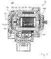
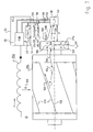
- the rings 206, 208 are connected in the usual way by shorting bars 210 into a cage in which a rotor current i R flows in operation, the size of which depends from the temperature of the rotor 204, because the resistance of the bars 210 increases with increasing temperature. For this reason, the height of the current must be adjusted depending on the rotor temperature, and for this reason, a temperature sensor whose position is indicated by the reference numeral 214 and which indirectly detects the temperature of the rotor 204 is integrated into the stator winding. The signal from this sensor 214 is fed to a field-oriented control (FOR) controller 20, which in Fig. 2 is shown.
- FOR field-oriented control
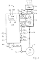
- FIG. 1 shows a control arrangement 10 for the ASM 12. It has an encoder arrangement 14 for generating a speed signal n, and also an encoder arrangement 14A (FIG. Fig. 1 ) for generating a Hall signal HALL and a signal MR from a magnetoresistive resistor 18 (FIG. Fig. 2 ).
- the encoder arrangement 14 includes a sensor magnet 274.
- the sensor magnet 274 also controls the magnetoresistor 18, which serves for the exact detection of the rotor position.
- the rotor position can also be calculated directly from the Hall signal HALL.
- the FOR 20 is also supplied at an input 50 with a value n * for the desired speed of the motor 10. Furthermore, values i1, i2, i3 for the phase currents are applied to inputs 52, 54, and values u1, u2, u3 for the phase voltages of the respective phases of the motor 12 are applied to inputs 56, 58.
- the currents i1 etc. are z. Example by means of current transformers 24 of known type, of which only one is shown because Fig. 1 a common symbolic representation for such a motor.
- a three-phase inverter 34 is connected, of which only one of the three branches is shown.
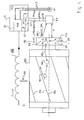
- Fig. 4 12 shows a schematic representation of the stator 202, the rotor 204 with the short-circuit bars 210 and with the sensor magnet 274, the galvanomagnetic sensor 14A, the MR sensor 18 for detecting the rotor position angle phi, and the ECU 33, which comprises a FOR 20 and a temperature evaluation device 44 Has.
- the temperature T_M 104 influenced by heat transfer 105, in particular by heat conduction, the temperature T_SM 106 of the sensor magnet 274, so that T_SM ⁇ T_M is.
- the sensor magnet 274 z. B. rotatably connected via a thermally conductive material with the rotor 204.
- the sensor magnet 274 rotates with the rotor 204 and generates a magnetic Flux density B (phi, T_SM) 108, which is dependent on the rotor position angle phi and the temperature T_SM 106 of the sensor magnet 274, wherein the amplitude of the magnetic flux density B 108 decreases with increasing temperature T_SM 106 of the sensor magnet 274.
- the determined voltage U112 is supplied to the temperature evaluation device CALC_T 44.
- T_SM amplitude f
- the determined temperature value T 45 is then supplied to the FOR 20, and this can perform an improved field-oriented control with the aid of the value T 45 and the rotor position angle phi determined by the MR sensor 18.
- the measurement of the temperature-dependent magnetic flux density 108 by means of a galvanomagnetic sensor 14A responds more quickly to temperature changes in the motor 12 than the measurement of the temperature at the location of the sensor 14A (for example, by an NTC resistor), since the heat transfer is not instantaneous, and therefore a temperature measurement at the location of the sensor 14A with respect to the temperature of the engine is delayed.
- the distance d ( Fig. 3 ) between the sensor magnet 274 and the galvanomagnetic sensor 14A is preferably selected such that it lies at approximately 2/3 of the radius r_SM 120 of the sensor magnet 274.
- r_SM is about 7 mm, and thus about 5 mm.
- a stator-side partition or cap 122 (FIG. Fig. 1 ) is provided between the sensor 14A and the sensor magnet 274, for. B. to protect the sensor 14A before engine-internal media such.
- the cap 122 is preferably made of a poor thermal conductivity material such. B. plastic designed to reduce heating of the sensor 14A.
- the sensor 14A can conduct heat well with the sensor housing 124 (FIG. Fig. 1 ) are thermally connected to maintain the temperature of the sensor 14A at about ambient temperature. This is when galvanomagnetic Sensors 14A with dependent on the temperature of the sensor 14A output signal 110 reduces an influence on the output signal 110 by heating the sensor 14A, which facilitates the evaluation.
- galvanomagnetic sensors 14A are used with compensation for the dependence on the sensor temperature.
- Such compensation is z. B. in the silicon of the sensor 14A possible.
- a suitable galvanomagnetic sensor 14A is e.g. Hall sensor HW-1 01 A from ASAHI KASEI EMD CORPORATION (AKE).
- a solution without an MR sensor 18 or 18 ' is also possible.
- two analog galvanomagnetic sensors 14A are used to generate two non-identical sine signals, preferably a sine signal and a cosine signal. The temperature can then be determined either from one or both signals.
- Fig. 5 shows from the data sheet of the Hall sensor HW-101A a characteristic V H -B with the output voltage V H and the magnetic flux density B, and Fig. 6 a characteristic V H -T with the output voltage V H and the temperature T.
- the output voltage V H increases linearly with the amount of the magnetic flux density B, provided that the input voltage Vc is kept constant.
- the level of the output voltage V H in the operating range -40 ° C to + 110 ° C of the temperature at a constant input voltage V C remains substantially constant.
- the voltage generated by the Hall sensor 14A voltage U 112 thus essentially depends on the - direction-independent - magnetic flux density B.
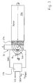
- Fig. 7 shows a schematic diagram of a measurement of the engine temperature T_M 104 by means of a relative to the rotor axis 150 centrally disposed MR sensor 18 '.
- the starting point is that the temperature T_SM of the sensor magnet 274 represents a sufficient image of the temperature T_M 104 of the short-circuit rotor 204.
- the MR sensor 18 ' (eg, an AMR, GMR, or CMR sensor) is positioned relative to the sensor magnet 274 such that heat transfer 134 from the sensor magnet 274 to the sensor 18' occurs, particularly by heat radiation and convection ,
- MR sensors 18 ' are used whose output signals 130, 132 in the specified range depend only slightly on the strength of the magnetic flux density B 108, but mainly on their direction (also called magnetic field direction), or in which the dependence on the magnetic flux density B is at least less than that of the temperature of the MR sensor 18 '.
- the output voltage decreases by about 0.29% / K, and it is substantially independent of the amount of magnetic field in the working region (usually in the saturation region with respect to the magnetic flux density B) Flux density B.
- the method is not as accurate as z.
- the solution is therefore very favorable because both the rotor position angle phi and the approximate temperature (T_M) 104 of the short-circuit rotor 204 can be determined with the MR sensor 140.
- the distance d between the sensor magnet 274 and the MR sensor 18 ' is preferably chosen small, z. B. 1 mm to 4 mm, more preferably 1.5 mm to 3 mm to allow a good heat transfer 134.
- stator-side partition or cap 122 (FIG. Fig. 1 ) between the sensor 18 'and the sensor magnet 274 to protect the sensor 18'.
- the partition 122 is made of a good heat conducting material such.
- a good heat conducting material such as a metal, in particular aluminum.
- the senor 18 or 18 'with respect to the usually good thermal conductivity sensor housing 124 are thermally insulated to reduce cooling therethrough.
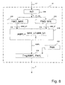
- Fig. 8 1 shows an exemplary embodiment of a temperature evaluation device (temperature determination device, temperature detection device) 44 for evaluating a temperature-dependent sensor signal U1 from a galvanomagnetic sensor 14A (FIG. Fig. 4 ) or an MR sensor 18 '( Fig. 7 ).
- a temperature evaluation device temperature determination device, temperature detection device 44 for evaluating a temperature-dependent sensor signal U1 from a galvanomagnetic sensor 14A (FIG. Fig. 4 ) or an MR sensor 18 '( Fig. 7 ).
- the device 44 is designed here as an ASIC, but can, for. B. also be formed in a microprocessor or microcontroller.
- the temperature-dependent signal U1 is fed to an A / D converter 304 and digitized there.
- the output signal U1_dig is fed to a function FIND_MAX 308 and a function FIND_MIN 310, which determine, for example, the maximum value MAX_U1 312 and the minimum value MIN_U1 314 over a predetermined period of time. For this purpose, z. B. during a period of the sinusoidal signal U1, the largest value and the smallest value are determined. Subsequently, at 316, the amplitude AMPL is calculated by calculating half of the difference between the maximum value MAX_U1 and the minimum value MIN_U1.
- the temperature T is subsequently determined from the amplitude AMPL and possibly further parameters PAR dependent on the motor or sensor by a function g (AMPL, PAR).
- the motor-dependent parameters PAR are z.
- EEPROM 320 Fig. 8
- the determination of the temperature can z.
- the parameter PAR 320 can be fixed for the engine type, with a higher requirement
- the accuracy or large tolerances may also be necessary, at least partially, for each individual rotor 204 determined specification of the parameters, wherein z. B. measurements are carried out at predetermined temperatures.
- the temperature can be determined either only from one of the two signals, or both. Upon detection of a sine and a cosine signal, these can be applied in a known manner as a circle, and the temperature results from its radius.
- the present type of temperature measurement can also be used with BLDC motors (brushless DC motors or electronically commutated DC motors) to allow regulation with a more accurate motor model.
- BLDC motors brushless DC motors or electronically commutated DC motors
- sensors 14A and 18, 18 ' which i.a. are dependent both on the magnitude of the magnetic flux density B and on the temperature T_S of the sensor 18, 18 '.
- this can complicate the evaluation, and the effects can cancel each other or negatively influence. Possibly.
- the characteristic of the determined voltage above the motor temperature must be measured in advance in the engine 12.
- both are preferably arranged on the same side of the printed circuit board; in the case of a galvanomagnetic and an MR sensor, either both sensors are preferably arranged on the same side of the printed circuit board, or one of the sensors is on the front side of the printed circuit board and the other on its rear side arranged.
- MR sensors are preferably used in the region of the axis of rotation 150 (FIG. Fig. 4 . Fig. 7 ) of the rotor or the sensor magnet 106 and thus arranged centrally, while galvanomagnetic sensors can be positioned relatively freely, especially in the exclusive use for temperature determination, as long as the magnetic flux density at the selected position is still large enough.
Landscapes
- Physics & Mathematics (AREA)
- General Physics & Mathematics (AREA)
- Control Of Motors That Do Not Use Commutators (AREA)
- Photoreceptors In Electrophotography (AREA)
- Brushless Motors (AREA)
Applications Claiming Priority (2)
| Application Number | Priority Date | Filing Date | Title |
|---|---|---|---|
| DE102007024244 | 2007-05-14 | ||
| DE102007039366 | 2007-08-15 |
Publications (2)
| Publication Number | Publication Date |
|---|---|
| EP1992927A1 true EP1992927A1 (fr) | 2008-11-19 |
| EP1992927B1 EP1992927B1 (fr) | 2011-04-27 |
Family
ID=39689169
Family Applications (1)
| Application Number | Title | Priority Date | Filing Date |
|---|---|---|---|
| EP08001598A Not-in-force EP1992927B1 (fr) | 2007-05-14 | 2008-01-29 | Moteur asynchrone commuté électroniquement |
Country Status (4)
| Country | Link |
|---|---|
| US (1) | US7936145B2 (fr) |
| EP (1) | EP1992927B1 (fr) |
| AT (1) | ATE507465T1 (fr) |
| DE (2) | DE502008003332D1 (fr) |
Cited By (1)
| Publication number | Priority date | Publication date | Assignee | Title |
|---|---|---|---|---|
| WO2011020648A1 (fr) * | 2009-08-20 | 2011-02-24 | Robert Bosch Gmbh | Détection de la température au moyen de variations de champ magnétique |
Families Citing this family (11)
| Publication number | Priority date | Publication date | Assignee | Title |
|---|---|---|---|---|
| DE102009001955A1 (de) * | 2009-03-27 | 2010-10-07 | Beckhoff Automation Gmbh | Verfahren und Verstärker zum Betreiben eines Synchronmotors |
| US20120181882A1 (en) * | 2011-01-14 | 2012-07-19 | Remy Technologies, L.L.C. | Electric machine having an integrated rotor temperature sensor |
| IT1404255B1 (it) * | 2011-01-25 | 2013-11-15 | Gate Srl | Dispositivo regolatore di tensione per un motoventilatore associato ad uno scambiatore di calore di un autoveicolo |
| JP5895774B2 (ja) * | 2012-09-04 | 2016-03-30 | 株式会社安川電機 | モータ |
| US9383267B2 (en) * | 2013-05-31 | 2016-07-05 | Purdue Research Foundation | Wireless sensor for rotating elements |
| DE102015012902A1 (de) | 2015-10-06 | 2017-04-06 | Audi Ag | Verfahren zum Bestimmen einer Temperatur eines Rotors |
| DE102016214497A1 (de) * | 2016-08-05 | 2018-02-08 | Schaeffler Technologies AG & Co. KG | Steuerungseinheit und Verfahren zum Steuern einer elektrischen Maschine |
| CN107192972B (zh) * | 2017-05-17 | 2019-08-23 | 常楚笛 | 一种核磁共振成像系统及其成像方法 |
| WO2019124985A1 (fr) * | 2017-12-20 | 2019-06-27 | Samsung Electronics Co., Ltd. | Moteur et machine à laver le comprenant |
| DE102022213833A1 (de) | 2022-12-19 | 2023-12-14 | Vitesco Technologies GmbH | Elektrische Maschine, Sensorvorrichtung, Auswerteeinheit und Verfahren zur Erfassung einer Temperatur eines Rotors |
| DE102023002861A1 (de) | 2023-07-14 | 2025-01-16 | Mercedes-Benz Group AG | Verfahren zum Ermitteln einer Rotortemperatur einer elektrischen Maschine |
Citations (6)
| Publication number | Priority date | Publication date | Assignee | Title |
|---|---|---|---|---|
| US3848466A (en) * | 1974-01-30 | 1974-11-19 | Atomic Energy Commission | Magnetic temperature sensor |
| GB2261518A (en) * | 1991-11-15 | 1993-05-19 | Heidelberger Druckmasch Ag | Apparatus for measuring at least one state variable of a brushless direct-current motor |
| DE19539711A1 (de) * | 1995-10-25 | 1997-04-30 | Tech Gmbh Antriebstechnik Und | Nachführung der Rotor-Zeitkonstanten bei Feldorientierung |
| EP0780964A2 (fr) * | 1995-12-22 | 1997-06-25 | PAPST-MOTOREN GmbH & Co. KG | Moteur commuté électroniquement |
| JPH10174276A (ja) | 1996-12-06 | 1998-06-26 | Matsushita Electric Ind Co Ltd | モータの保護装置 |
| JP2004222387A (ja) | 2003-01-14 | 2004-08-05 | Toyota Motor Corp | 永久磁石温度センサ、永久磁石モータ、永久磁石モータの駆動システム |
Family Cites Families (12)
| Publication number | Priority date | Publication date | Assignee | Title |
|---|---|---|---|---|
| DE3205460A1 (de) | 1982-02-16 | 1983-02-03 | Martin 7430 Metzingen Graser | Beruehrungslose, rueckwirkungsfreie temperaturmessung mit permanentmagnet, eichkurve und hallgenerator |
| JPS6016184A (ja) | 1983-07-06 | 1985-01-26 | Mitsubishi Electric Corp | エレベ−タの制御装置 |
| WO1991001062A1 (fr) * | 1989-07-10 | 1991-01-24 | Sanyo Electric Co., Ltd. | Procede et dispositif de commande de moteurs a induction de compresseurs |
| GB2255866B (en) * | 1991-05-14 | 1995-08-02 | Rotork Controls | An actuactor and an electric motor drive system |
| US5811957A (en) * | 1995-12-21 | 1998-09-22 | General Motors Corporation | Speed sensorless hybrid vector controlled induction motor with zero speed operation |
| DE19928481B4 (de) | 1999-06-22 | 2009-12-10 | Robert Bosch Gmbh | Verfahren zur vereinfachten feldorientierten Regelung von Asynchronmaschinen |
| DE19942205A1 (de) | 1999-09-03 | 2001-03-15 | Sew Eurodrive Gmbh & Co | Steuerverfahren für einen Umrichter zur feldorientierten Regelung eines Elektromotors und Umrichter |
| US7199549B2 (en) * | 2001-08-17 | 2007-04-03 | Delphi Technologies, Inc | Feedback parameter estimation for electric machines |
| JP2005061709A (ja) | 2003-08-11 | 2005-03-10 | Toshiba Corp | 冷蔵庫の冷却ファン駆動装置 |
| KR100756725B1 (ko) | 2003-11-28 | 2007-09-07 | 가부시끼가이샤 도시바 | 냉장고 |
| JP2005180874A (ja) | 2003-12-22 | 2005-07-07 | Toshiba Corp | 冷蔵庫 |
| US7268514B2 (en) * | 2004-11-30 | 2007-09-11 | Rockwell Automation Technologies, Inc. | Motor control for stopping a load and detecting mechanical brake slippage |
-
2008
- 2008-01-29 DE DE502008003332T patent/DE502008003332D1/de active Active
- 2008-01-29 AT AT08001598T patent/ATE507465T1/de active
- 2008-01-29 EP EP08001598A patent/EP1992927B1/fr not_active Not-in-force
- 2008-04-15 DE DE102008018843A patent/DE102008018843A1/de not_active Withdrawn
- 2008-04-30 US US12/112,130 patent/US7936145B2/en not_active Expired - Fee Related
Patent Citations (6)
| Publication number | Priority date | Publication date | Assignee | Title |
|---|---|---|---|---|
| US3848466A (en) * | 1974-01-30 | 1974-11-19 | Atomic Energy Commission | Magnetic temperature sensor |
| GB2261518A (en) * | 1991-11-15 | 1993-05-19 | Heidelberger Druckmasch Ag | Apparatus for measuring at least one state variable of a brushless direct-current motor |
| DE19539711A1 (de) * | 1995-10-25 | 1997-04-30 | Tech Gmbh Antriebstechnik Und | Nachführung der Rotor-Zeitkonstanten bei Feldorientierung |
| EP0780964A2 (fr) * | 1995-12-22 | 1997-06-25 | PAPST-MOTOREN GmbH & Co. KG | Moteur commuté électroniquement |
| JPH10174276A (ja) | 1996-12-06 | 1998-06-26 | Matsushita Electric Ind Co Ltd | モータの保護装置 |
| JP2004222387A (ja) | 2003-01-14 | 2004-08-05 | Toyota Motor Corp | 永久磁石温度センサ、永久磁石モータ、永久磁石モータの駆動システム |
Cited By (1)
| Publication number | Priority date | Publication date | Assignee | Title |
|---|---|---|---|---|
| WO2011020648A1 (fr) * | 2009-08-20 | 2011-02-24 | Robert Bosch Gmbh | Détection de la température au moyen de variations de champ magnétique |
Also Published As
| Publication number | Publication date |
|---|---|
| EP1992927B1 (fr) | 2011-04-27 |
| US20080284364A1 (en) | 2008-11-20 |
| ATE507465T1 (de) | 2011-05-15 |
| DE502008003332D1 (de) | 2011-06-09 |
| US7936145B2 (en) | 2011-05-03 |
| DE102008018843A1 (de) | 2008-11-20 |
Similar Documents
| Publication | Publication Date | Title |
|---|---|---|
| EP1992927B1 (fr) | Moteur asynchrone commuté électroniquement | |
| DE102013016911B4 (de) | Temperaturschätzvorrichtung zum Abschätzen der Temperatur eines Motors | |
| DE60223466T3 (de) | Aktive Temperaturschätzung für elektrische Maschinen | |
| DE102016006338B4 (de) | Temperaturschätzvorrichtung für einen Synchronmotor | |
| DE19504287B4 (de) | Drehmoment-Erfassungsvorrichtung für einen Wechselstrommotor | |
| EP1727268A2 (fr) | Procédé pour faire fonctionner un moteur à commutation électronique et moteur pour la mise en oeuvre dudit procédé | |
| EP2459970B1 (fr) | Entraînement électrique commuté et procédé de commande d'un moteur électrique commuté | |
| DE102010003475A1 (de) | Drehwinkel-messgerät und drehzahl-messgerät | |
| DE102011055717B4 (de) | Verfahren und Anordnung zur Bestimmung des dynamischen Zustands eines Elektromotors | |
| DE102019115787B3 (de) | Verfahren zur Ermittlung des Winkels des Rotors eines Elektromotors, Steuergerät sowie Fahrzeug | |
| EP2853873A1 (fr) | Dispositif et procédé de détection d'une température d'un rotor d'un moteur électrique | |
| WO2007012370A1 (fr) | Moteur electrique sans balai | |
| DE102016200318A1 (de) | Vorrichtung und verfahren zum messen der versetzung eines eps-motorpositionssensors | |
| WO2018082902A1 (fr) | Procédé permettant de déterminer la position angulaire de rotation d'un vilebrequin d'un moteur à combustion interne | |
| DE112020005865B4 (de) | Verarbeitungseinrichtung und Verfahren zur Bestimmung eines Modells zur Berechnung von Wicklungstemperaturen | |
| DE102010040584A1 (de) | Verfahren und Vorrichtung zur Störfeldkompensation von magnetischen Winkelsensoren | |
| EP3703246A1 (fr) | Dispositif et procédé de détection de la température d'enroulement | |
| DE102014005874A1 (de) | Motorantriebsvorrichtung | |
| EP3833933B1 (fr) | Capteur de position inductif, en particulier pour acquérir au moins une caractéristique de rotation d'un élément rotatif | |
| WO2011092320A2 (fr) | Unité de détection à fixer sur une machine électrique et système de moteur | |
| EP1872466A1 (fr) | Procede de determination de position sans capteur du rotor d'un moteur electrique | |
| DE112017007123B4 (de) | Leistungswandlungsvorrichtung für ein Elektrofahrzeug | |
| DE102012021020A1 (de) | Verfahren und Vorrichtung zum Bestimmen einer Betriebstemperatur eines Elektromotors | |
| EP3157165A1 (fr) | Procédé de détermination d'une température d'un rotor | |
| DE112018005090T5 (de) | Vakuumpumpe und Steuerungsverfahren dafür |
Legal Events
| Date | Code | Title | Description |
|---|---|---|---|
| PUAI | Public reference made under article 153(3) epc to a published international application that has entered the european phase |
Free format text: ORIGINAL CODE: 0009012 |
|
| 17P | Request for examination filed |
Effective date: 20080922 |
|
| AK | Designated contracting states |
Kind code of ref document: A1 Designated state(s): AT BE BG CH CY CZ DE DK EE ES FI FR GB GR HR HU IE IS IT LI LT LU LV MC MT NL NO PL PT RO SE SI SK TR |
|
| AX | Request for extension of the european patent |
Extension state: AL BA MK RS |
|
| AKX | Designation fees paid |
Designated state(s): AT BE BG CH CY CZ DE DK EE ES FI FR GB GR HR HU IE IS IT LI LT LU LV MC MT NL NO PL PT RO SE SI SK TR |
|
| 17Q | First examination report despatched |
Effective date: 20091009 |
|
| GRAP | Despatch of communication of intention to grant a patent |
Free format text: ORIGINAL CODE: EPIDOSNIGR1 |
|
| RTI1 | Title (correction) |
Free format text: ELECTRONICALLY COMMUTATED INDUCTION MOTOR |
|
| GRAS | Grant fee paid |
Free format text: ORIGINAL CODE: EPIDOSNIGR3 |
|
| GRAA | (expected) grant |
Free format text: ORIGINAL CODE: 0009210 |
|
| AK | Designated contracting states |
Kind code of ref document: B1 Designated state(s): AT BE BG CH CY CZ DE DK EE ES FI FR GB GR HR HU IE IS IT LI LT LU LV MC MT NL NO PL PT RO SE SI SK TR |
|
| REG | Reference to a national code |
Ref country code: GB Ref legal event code: FG4D Free format text: NOT ENGLISH |
|
| REG | Reference to a national code |
Ref country code: CH Ref legal event code: EP |
|
| REG | Reference to a national code |
Ref country code: IE Ref legal event code: FG4D Free format text: LANGUAGE OF EP DOCUMENT: GERMAN |
|
| REF | Corresponds to: |
Ref document number: 502008003332 Country of ref document: DE Date of ref document: 20110609 Kind code of ref document: P |
|
| REG | Reference to a national code |
Ref country code: DE Ref legal event code: R096 Ref document number: 502008003332 Country of ref document: DE Effective date: 20110609 |
|
| REG | Reference to a national code |
Ref country code: SE Ref legal event code: TRGR |
|
| REG | Reference to a national code |
Ref country code: NL Ref legal event code: VDEP Effective date: 20110427 |
|
| LTIE | Lt: invalidation of european patent or patent extension |
Effective date: 20110427 |
|
| PG25 | Lapsed in a contracting state [announced via postgrant information from national office to epo] |
Ref country code: NO Free format text: LAPSE BECAUSE OF FAILURE TO SUBMIT A TRANSLATION OF THE DESCRIPTION OR TO PAY THE FEE WITHIN THE PRESCRIBED TIME-LIMIT Effective date: 20110727 Ref country code: HR Free format text: LAPSE BECAUSE OF FAILURE TO SUBMIT A TRANSLATION OF THE DESCRIPTION OR TO PAY THE FEE WITHIN THE PRESCRIBED TIME-LIMIT Effective date: 20110427 Ref country code: LT Free format text: LAPSE BECAUSE OF FAILURE TO SUBMIT A TRANSLATION OF THE DESCRIPTION OR TO PAY THE FEE WITHIN THE PRESCRIBED TIME-LIMIT Effective date: 20110427 Ref country code: PT Free format text: LAPSE BECAUSE OF FAILURE TO SUBMIT A TRANSLATION OF THE DESCRIPTION OR TO PAY THE FEE WITHIN THE PRESCRIBED TIME-LIMIT Effective date: 20110829 |
|
| REG | Reference to a national code |
Ref country code: IE Ref legal event code: FD4D |
|
| PG25 | Lapsed in a contracting state [announced via postgrant information from national office to epo] |
Ref country code: CY Free format text: LAPSE BECAUSE OF FAILURE TO SUBMIT A TRANSLATION OF THE DESCRIPTION OR TO PAY THE FEE WITHIN THE PRESCRIBED TIME-LIMIT Effective date: 20110427 Ref country code: GR Free format text: LAPSE BECAUSE OF FAILURE TO SUBMIT A TRANSLATION OF THE DESCRIPTION OR TO PAY THE FEE WITHIN THE PRESCRIBED TIME-LIMIT Effective date: 20110728 Ref country code: LV Free format text: LAPSE BECAUSE OF FAILURE TO SUBMIT A TRANSLATION OF THE DESCRIPTION OR TO PAY THE FEE WITHIN THE PRESCRIBED TIME-LIMIT Effective date: 20110427 Ref country code: IS Free format text: LAPSE BECAUSE OF FAILURE TO SUBMIT A TRANSLATION OF THE DESCRIPTION OR TO PAY THE FEE WITHIN THE PRESCRIBED TIME-LIMIT Effective date: 20110827 Ref country code: SI Free format text: LAPSE BECAUSE OF FAILURE TO SUBMIT A TRANSLATION OF THE DESCRIPTION OR TO PAY THE FEE WITHIN THE PRESCRIBED TIME-LIMIT Effective date: 20110427 Ref country code: ES Free format text: LAPSE BECAUSE OF FAILURE TO SUBMIT A TRANSLATION OF THE DESCRIPTION OR TO PAY THE FEE WITHIN THE PRESCRIBED TIME-LIMIT Effective date: 20110807 |
|
| PG25 | Lapsed in a contracting state [announced via postgrant information from national office to epo] |
Ref country code: NL Free format text: LAPSE BECAUSE OF FAILURE TO SUBMIT A TRANSLATION OF THE DESCRIPTION OR TO PAY THE FEE WITHIN THE PRESCRIBED TIME-LIMIT Effective date: 20110427 |
|
| PG25 | Lapsed in a contracting state [announced via postgrant information from national office to epo] |
Ref country code: IE Free format text: LAPSE BECAUSE OF FAILURE TO SUBMIT A TRANSLATION OF THE DESCRIPTION OR TO PAY THE FEE WITHIN THE PRESCRIBED TIME-LIMIT Effective date: 20110427 Ref country code: EE Free format text: LAPSE BECAUSE OF FAILURE TO SUBMIT A TRANSLATION OF THE DESCRIPTION OR TO PAY THE FEE WITHIN THE PRESCRIBED TIME-LIMIT Effective date: 20110427 Ref country code: CZ Free format text: LAPSE BECAUSE OF FAILURE TO SUBMIT A TRANSLATION OF THE DESCRIPTION OR TO PAY THE FEE WITHIN THE PRESCRIBED TIME-LIMIT Effective date: 20110427 |
|
| PG25 | Lapsed in a contracting state [announced via postgrant information from national office to epo] |
Ref country code: SK Free format text: LAPSE BECAUSE OF FAILURE TO SUBMIT A TRANSLATION OF THE DESCRIPTION OR TO PAY THE FEE WITHIN THE PRESCRIBED TIME-LIMIT Effective date: 20110427 Ref country code: RO Free format text: LAPSE BECAUSE OF FAILURE TO SUBMIT A TRANSLATION OF THE DESCRIPTION OR TO PAY THE FEE WITHIN THE PRESCRIBED TIME-LIMIT Effective date: 20110427 Ref country code: DK Free format text: LAPSE BECAUSE OF FAILURE TO SUBMIT A TRANSLATION OF THE DESCRIPTION OR TO PAY THE FEE WITHIN THE PRESCRIBED TIME-LIMIT Effective date: 20110427 Ref country code: PL Free format text: LAPSE BECAUSE OF FAILURE TO SUBMIT A TRANSLATION OF THE DESCRIPTION OR TO PAY THE FEE WITHIN THE PRESCRIBED TIME-LIMIT Effective date: 20110427 |
|
| PLBE | No opposition filed within time limit |
Free format text: ORIGINAL CODE: 0009261 |
|
| STAA | Information on the status of an ep patent application or granted ep patent |
Free format text: STATUS: NO OPPOSITION FILED WITHIN TIME LIMIT |
|
| 26N | No opposition filed |
Effective date: 20120130 |
|
| REG | Reference to a national code |
Ref country code: DE Ref legal event code: R097 Ref document number: 502008003332 Country of ref document: DE Effective date: 20120130 |
|
| BERE | Be: lapsed |
Owner name: EBM-PAPST ST. GEORGEN G.M.B.H. & CO. KG Effective date: 20120131 |
|
| PG25 | Lapsed in a contracting state [announced via postgrant information from national office to epo] |
Ref country code: MC Free format text: LAPSE BECAUSE OF NON-PAYMENT OF DUE FEES Effective date: 20120131 |
|
| REG | Reference to a national code |
Ref country code: CH Ref legal event code: PL |
|
| PG25 | Lapsed in a contracting state [announced via postgrant information from national office to epo] |
Ref country code: CH Free format text: LAPSE BECAUSE OF NON-PAYMENT OF DUE FEES Effective date: 20120131 Ref country code: LI Free format text: LAPSE BECAUSE OF NON-PAYMENT OF DUE FEES Effective date: 20120131 |
|
| PG25 | Lapsed in a contracting state [announced via postgrant information from national office to epo] |
Ref country code: BE Free format text: LAPSE BECAUSE OF NON-PAYMENT OF DUE FEES Effective date: 20120131 |
|
| PG25 | Lapsed in a contracting state [announced via postgrant information from national office to epo] |
Ref country code: BG Free format text: LAPSE BECAUSE OF FAILURE TO SUBMIT A TRANSLATION OF THE DESCRIPTION OR TO PAY THE FEE WITHIN THE PRESCRIBED TIME-LIMIT Effective date: 20110727 |
|
| PG25 | Lapsed in a contracting state [announced via postgrant information from national office to epo] |
Ref country code: MT Free format text: LAPSE BECAUSE OF FAILURE TO SUBMIT A TRANSLATION OF THE DESCRIPTION OR TO PAY THE FEE WITHIN THE PRESCRIBED TIME-LIMIT Effective date: 20110427 |
|
| REG | Reference to a national code |
Ref country code: AT Ref legal event code: MM01 Ref document number: 507465 Country of ref document: AT Kind code of ref document: T Effective date: 20130129 |
|
| PG25 | Lapsed in a contracting state [announced via postgrant information from national office to epo] |
Ref country code: TR Free format text: LAPSE BECAUSE OF FAILURE TO SUBMIT A TRANSLATION OF THE DESCRIPTION OR TO PAY THE FEE WITHIN THE PRESCRIBED TIME-LIMIT Effective date: 20110427 |
|
| PG25 | Lapsed in a contracting state [announced via postgrant information from national office to epo] |
Ref country code: AT Free format text: LAPSE BECAUSE OF NON-PAYMENT OF DUE FEES Effective date: 20130129 Ref country code: LU Free format text: LAPSE BECAUSE OF NON-PAYMENT OF DUE FEES Effective date: 20120129 |
|
| PG25 | Lapsed in a contracting state [announced via postgrant information from national office to epo] |
Ref country code: HU Free format text: LAPSE BECAUSE OF FAILURE TO SUBMIT A TRANSLATION OF THE DESCRIPTION OR TO PAY THE FEE WITHIN THE PRESCRIBED TIME-LIMIT Effective date: 20080129 |
|
| PGFP | Annual fee paid to national office [announced via postgrant information from national office to epo] |
Ref country code: FR Payment date: 20141126 Year of fee payment: 8 |
|
| PGFP | Annual fee paid to national office [announced via postgrant information from national office to epo] |
Ref country code: IT Payment date: 20141022 Year of fee payment: 8 |
|
| PGFP | Annual fee paid to national office [announced via postgrant information from national office to epo] |
Ref country code: DE Payment date: 20150107 Year of fee payment: 8 Ref country code: FI Payment date: 20150102 Year of fee payment: 8 |
|
| PGFP | Annual fee paid to national office [announced via postgrant information from national office to epo] |
Ref country code: SE Payment date: 20150123 Year of fee payment: 8 Ref country code: GB Payment date: 20150128 Year of fee payment: 8 |
|
| REG | Reference to a national code |
Ref country code: DE Ref legal event code: R119 Ref document number: 502008003332 Country of ref document: DE |
|
| GBPC | Gb: european patent ceased through non-payment of renewal fee |
Effective date: 20160129 |
|
| REG | Reference to a national code |
Ref country code: FR Ref legal event code: ST Effective date: 20160930 |
|
| PG25 | Lapsed in a contracting state [announced via postgrant information from national office to epo] |
Ref country code: FI Free format text: LAPSE BECAUSE OF NON-PAYMENT OF DUE FEES Effective date: 20160129 Ref country code: DE Free format text: LAPSE BECAUSE OF NON-PAYMENT OF DUE FEES Effective date: 20160802 Ref country code: GB Free format text: LAPSE BECAUSE OF NON-PAYMENT OF DUE FEES Effective date: 20160129 |
|
| PG25 | Lapsed in a contracting state [announced via postgrant information from national office to epo] |
Ref country code: FR Free format text: LAPSE BECAUSE OF NON-PAYMENT OF DUE FEES Effective date: 20160201 Ref country code: SE Free format text: LAPSE BECAUSE OF NON-PAYMENT OF DUE FEES Effective date: 20160130 |
|
| PG25 | Lapsed in a contracting state [announced via postgrant information from national office to epo] |
Ref country code: IT Free format text: LAPSE BECAUSE OF NON-PAYMENT OF DUE FEES Effective date: 20160129 |