EP3157165A1 - Procédé de détermination d'une température d'un rotor - Google Patents
Procédé de détermination d'une température d'un rotor Download PDFInfo
- Publication number
- EP3157165A1 EP3157165A1 EP16191366.0A EP16191366A EP3157165A1 EP 3157165 A1 EP3157165 A1 EP 3157165A1 EP 16191366 A EP16191366 A EP 16191366A EP 3157165 A1 EP3157165 A1 EP 3157165A1
- Authority
- EP
- European Patent Office
- Prior art keywords
- rotor
- stator
- electric machine
- inductance
- value
- Prior art date
- Legal status (The legal status is an assumption and is not a legal conclusion. Google has not performed a legal analysis and makes no representation as to the accuracy of the status listed.)
- Ceased
Links
Images
Classifications
-
- H—ELECTRICITY
- H02—GENERATION; CONVERSION OR DISTRIBUTION OF ELECTRIC POWER
- H02P—CONTROL OR REGULATION OF ELECTRIC MOTORS, ELECTRIC GENERATORS OR DYNAMO-ELECTRIC CONVERTERS; CONTROLLING TRANSFORMERS, REACTORS OR CHOKE COILS
- H02P29/00—Arrangements for regulating or controlling electric motors, appropriate for both AC and DC motors
- H02P29/60—Controlling or determining the temperature of the motor or of the drive
- H02P29/66—Controlling or determining the temperature of the rotor
-
- G—PHYSICS
- G01—MEASURING; TESTING
- G01R—MEASURING ELECTRIC VARIABLES; MEASURING MAGNETIC VARIABLES
- G01R31/00—Arrangements for testing electric properties; Arrangements for locating electric faults; Arrangements for electrical testing characterised by what is being tested not provided for elsewhere
- G01R31/34—Testing dynamo-electric machines
- G01R31/343—Testing dynamo-electric machines in operation
-
- H—ELECTRICITY
- H02—GENERATION; CONVERSION OR DISTRIBUTION OF ELECTRIC POWER
- H02P—CONTROL OR REGULATION OF ELECTRIC MOTORS, ELECTRIC GENERATORS OR DYNAMO-ELECTRIC CONVERTERS; CONTROLLING TRANSFORMERS, REACTORS OR CHOKE COILS
- H02P21/00—Arrangements or methods for the control of electric machines by vector control, e.g. by control of field orientation
- H02P21/14—Estimation or adaptation of machine parameters, e.g. flux, current or voltage
-
- H—ELECTRICITY
- H02—GENERATION; CONVERSION OR DISTRIBUTION OF ELECTRIC POWER
- H02P—CONTROL OR REGULATION OF ELECTRIC MOTORS, ELECTRIC GENERATORS OR DYNAMO-ELECTRIC CONVERTERS; CONTROLLING TRANSFORMERS, REACTORS OR CHOKE COILS
- H02P23/00—Arrangements or methods for the control of AC motors characterised by a control method other than vector control
- H02P23/14—Estimation or adaptation of motor parameters, e.g. rotor time constant, flux, speed, current or voltage
Definitions
- the invention relates to a method and a device for determining a temperature of a rotor of an electric machine.
- An electric machine which can be used as a generator and / or as a motor, comprises as components a fixed stator and a rotor rotating relative to the stator. To operate the electric machine, among other things, it is necessary to currently record their operating parameters. However, since the rotor can rotate relatively quickly during operation of the electric machine, it is usually not possible to directly detect some operating parameters of the rotor, for example by measurement.
- a method for operating a separately excited synchronous machine is known from the document DE 10 2010 014 173 A1 known.
- a flow of a rotor of the synchronous machine is determined with a model and from this an excitation current is determined.
- An electronically commutated asynchronous motor in the publication DE 10 2008 018 843 A1 includes a sensor for determining a position of a rotor, wherein based on a detected position, a temperature in the asynchronous motor is to characterize.
- EP 2 120 329 A2 It is described to estimate a temperature of a rotor of an induction motor based on various quantities resulting from an operation of the induction motor.
- the method according to the invention is designed to determine a temperature T R of a rotor of an electric machine, which is rotatable relative to a stator of the electric machine.
- the operating parameters of the electric machine applied to the stator voltage U S a current flowing through the stator I S , a rotational frequency ⁇ R of the rotor, a rotating field frequency ⁇ S of the stator, an inductance L R of the rotor, an inductance L S of the stator and a main inductance L H of the electric machine determined.
- a current value of the temperature T R of the rotor is determined as a function of the electrical resistance R R as the operating parameter of the rotor.
- inductance L of the rotor R Values of inductance L of the rotor R, the inductance L S of the stator and the main inductance L H of the electric machine according to specifications, for example. A table or a characteristic curve, specified and recorded.
- the specification is provided in an embodiment based on the values determined in the test bench.
- .DELTA.R ⁇ R R . Ref .DELTA.T
- R R , Ref is a reference value for the resistor R R and T R
- Ref is a reference value for the temperature T R of the rotor, these reference values being correlated with one another and, for example, also being determined in the test bench.
- T R , Ref 20 ° C. is the reference value of the temperature T R at which the reference value R R , Ref of the resistance results due to material properties of the rotor.
- the current value of the temperature T R is determined by the current value of the resistor R R in relation to T R , Ref and R R, Ref .
- the mutually associated reference values T R , Ref and R R , Ref for temperature and resistance are also determined in the test rig in an embodiment.
- T R R R - R R . Ref ⁇ R R . Ref + T R . Ref calculated.
- ⁇ is a coefficient dependent on the material of the rotor
- R R , Ref is the reference value of the electrical resistance R R of the rotor
- T R Ref is the reference value of the temperature T R of the rotor.
- the rotor has the reference value R R , Ref of the electrical resistance R R , when the rotor has the reference value T R , Ref the temperature T R and vice versa.
- the device according to the invention is designed to determine a temperature T R of a rotor of an electric machine, which is rotatable relative to a stator of the electric machine, and comprises at least one measuring device, at least one detection device and a control device.
- the at least one measuring device is designed to measure, as operating parameter of the electric machine, a voltage U S applied to the stator, a current I S flowing through the stator, a rotational frequency ⁇ R of the rotor and a rotational field frequency ⁇ S of the stator, and thus to determine it.
- the at least one detection device is designed to determine an inductance L S of the stator, an inductance L R of the rotor and a main inductance L H of the electric machine.
- a first measuring device is embodied as a voltage measuring device assigned to the stator and / or to be assigned, which is designed to measure at least one value of the voltage U S applied to the stator.
- a second measuring device is embodied as a measuring device assigned to and / or associated with the stator and designed to detect at least one value of the current I S flowing through the stator.
- a third measuring device is embodied as a rotational frequency measuring device or rotational speed measuring device assigned to and / or associated with the rotor, which is designed to determine at least one value of the rotational frequency ⁇ R of the rotor.
- a fourth measuring device is embodied as a rotating field frequency measuring device assigned to the stator and / or to be assigned, which is designed to measure at least one value of the rotating field frequency ⁇ S of the stator.
- values of electrical and mechanical operating parameters of at least one component i. H. measured and / or detected the stator and / or the rotor of the electric machine.
- the control unit usually comprises a computing unit and a memory unit. Values of inductance L R of the rotor, the inductance L S of the stator and the main inductance I H of the electric machine, according to a default, for example. From a table or curve to detect, with this requirement, which can be provided as a table or characteristic in the storage unit is stored.
- the device also comprises a test stand having a plurality of detection devices, wherein a first detection device associated with the rotor and / or assigned and adapted to detect at least one value of the inductance L R of the rotor, wherein a second detection device associated with the stator and / or is assigned and designed to determine at least one value of the inductance L S of the stator, wherein a third detection device associated with the electric machine and / or assigned and is designed to determine at least one value of the main inductance L H of the electric machine.
- the rotor rotates as the first component of the electric machine during operation of the electric machine relative to the stator as the second component of the electric machine.
- one of the two components usually the rotor, on permanent magnets, which generate a permanent magnetic field.
- the other of the two components usually the stator, in contrast, has several coils.
- the electric machine is to operate as a motor and / or as a generator. When operated as a motor, electrical current is passed through the coils, thus inducing a magnetic field that interacts with the permanent magnetic field. In this way it is possible to convert electrical energy into mechanical energy, usually rotational energy, with the electric machine. If the electric machine is alternatively or additionally operated as a generator, the rotor is mechanically rotated, wherein a current is induced in the coils and thus mechanical energy is converted into electrical energy.
- the temperature of the electric machine designed, for example, as an asynchronous machine is indirectly determined via the electrical resistance of the rotor to be determined.
- a temperature sensor or a To arrange thermometer it is possible, by means of a temperature model, which is stored as a default in the control unit or a converter of the electric machine to determine the value of the temperature from the detected current value of the resistance of the rotor, taking into account a dependence of the temperature of the resistor.
- it is provided for determining the temperature of the rotor to also take into account values of a load profile of the electric machine and / or a temperature of the stator.
- the temperature of the rotor at a start of the electric machine is calculated rather than merely estimated.
- the method is also feasible if the temperature of the rotor after a restart of the electric machine should be unknown. Thus, it is not necessary to know which temperature the rotor has exhibited, for example, when switching off the electric machine and how much time has elapsed after switching off the electric machine to restart.
- a direct relationship between the resistance and the temperature of the rotor is taken into account for the electric machine designed as an asynchronous machine, for example.
- the current values of the current and the voltage of the stator are measured with the at least one measuring device, which is arranged, for example, in a converter of the electric machine.
- the speed of the rotor is measured, for example, with a designed as a speed sensor measuring device. From the measured speed of the rotor whose rotational frequency is further derived.
- the inductances of the rotor, of the stator and of the entire electric machine to be taken into account before the actual operation or Load operation of the electric machine determined as characteristics of the electric machine.
- the values for the inductances determined in the test bench are stored in the memory unit of the control unit.
- the current rotating field frequency usually a rotating field frequency of the magnetic field of the stator, is detected and / or determined by the converter as the at least one detection device. In this case, this magnetic field is, for example, by the current flowing through the coils, usually coils of the stator, induced.
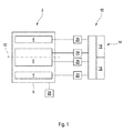
- FIG. 1 shows a schematic representation of a longitudinal section through an embodiment of the device according to the invention when carrying out an embodiment of the method according to the invention.
- FIG. 1 shows a schematic representation of an electric machine 2, which has as components a stator 4 and a rotor 6, both of which are arranged in a housing 8, wherein the stator 4 here at least partially surrounds the rotor 6, possibly completely coaxially.
- a rotation axis 10 is provided for the stator 6, which, for example, extends along a shaft of the electric machine 2, around which the rotor 6 rotates in a motor and / or regenerative operation of the electric machine 2 relative to the stator 4.
- the embodiment of the device 12 comprises as components a control device 14, which in turn comprises a computing unit 16 and a memory unit 18.
- the device 12 comprises at least one measuring device 20 and at least one detection device 22, which are associated with the stator 4 and designed to measure and / or detect at least one operating parameter of the stator 4.
- the device comprises at least one measuring device 24 and at least one detection device 26, which are here assigned to the rotor 6 and designed to measure and / or detect at least one operating parameter of the rotor 6.
- control device 14 and at least one measuring device 20, 24 and / or at least one detection device 22, 26 are or are designed as components or components of the electric machine 2, usually an inverter of the electric machine 2. At least one component is further configured to measure and / or to supply at least one operating parameter of the electric machine 2 during a running operation of the electric machine 2, for example a load operation, and / or in a test stand for the electric machine 2 before the actual operation of the electric machine 2 to capture.
- a voltage applied to the stator 4, a current I S flowing through the stator 4 and a rotational field frequency ⁇ S of the stator 4 are measured by the measuring device 20.
- the rotational field frequency ⁇ S indicates a change in a magnetic field of the stator 4.
- the rotational frequency ⁇ R of the rotor 6 is measured during operation.
- the inductance L S of the stator 4 is detected in the test bed.
- the inductance L R of the rotor 6 is also detected by the detection device 26 in the test stand.
- the inductance or main inductance I H of the entire electric machine 2 is detected in the test bench. Values of the inductances detected in the test stand before the actual operation of the electric machine 2 are stored in the memory unit 18 of the control unit 14.
- the control unit 14 usually the arithmetic unit 16 of the control unit 14, takes into account equations (1) and (2):
- R R ⁇ R L R ⁇ U S 2 - L S ⁇ S I S 2 L S ⁇ S I S ⁇ 2 - U S 2
- T R R R - R R . Ref ⁇ R R . Ref + T R . Ref determined.
- ⁇ is a coefficient dependent on the material of the rotor 6, the value of which is stored in the memory unit 18.
- a reference value R R , Ref the temperature of the rotor and a reference value T R , Ref the temperature of the rotor 4 to be considered.
- at least one value pair of said reference values R R , Ref , T R, Ref is also stored in the memory unit 18. If a plurality of such value pairs are stored in the memory unit 18, these form, for example, a characteristic curve or a table for a relationship between the temperature and the resistance of the rotor 6.
Landscapes
- Engineering & Computer Science (AREA)
- Power Engineering (AREA)
- Physics & Mathematics (AREA)
- General Physics & Mathematics (AREA)
- Tests Of Circuit Breakers, Generators, And Electric Motors (AREA)
- Control Of Ac Motors In General (AREA)
Applications Claiming Priority (1)
| Application Number | Priority Date | Filing Date | Title |
|---|---|---|---|
| DE102015012902.3A DE102015012902A1 (de) | 2015-10-06 | 2015-10-06 | Verfahren zum Bestimmen einer Temperatur eines Rotors |
Publications (1)
| Publication Number | Publication Date |
|---|---|
| EP3157165A1 true EP3157165A1 (fr) | 2017-04-19 |
Family
ID=57042733
Family Applications (1)
| Application Number | Title | Priority Date | Filing Date |
|---|---|---|---|
| EP16191366.0A Ceased EP3157165A1 (fr) | 2015-10-06 | 2016-09-29 | Procédé de détermination d'une température d'un rotor |
Country Status (2)
| Country | Link |
|---|---|
| EP (1) | EP3157165A1 (fr) |
| DE (1) | DE102015012902A1 (fr) |
Cited By (2)
| Publication number | Priority date | Publication date | Assignee | Title |
|---|---|---|---|---|
| CN110611473A (zh) * | 2018-06-05 | 2019-12-24 | 庞巴迪运输有限公司 | 用于确定转子的温度的方法和设备 |
| DE102021212801A1 (de) | 2021-11-15 | 2023-05-17 | Mahle International Gmbh | Verfahren zur Bestimmung einer Temperatur in einer Rotorerregung-Schaltung |
Families Citing this family (2)
| Publication number | Priority date | Publication date | Assignee | Title |
|---|---|---|---|---|
| DE102023002861A1 (de) | 2023-07-14 | 2025-01-16 | Mercedes-Benz Group AG | Verfahren zum Ermitteln einer Rotortemperatur einer elektrischen Maschine |
| DE102024117995A1 (de) * | 2024-06-26 | 2025-12-31 | Audi Aktiengesellschaft | Rotortemperaturabhängiges Betriebsverfahren für ein Elektrofahrzeug |
Citations (7)
| Publication number | Priority date | Publication date | Assignee | Title |
|---|---|---|---|---|
| DE1003301B (de) | 1955-05-16 | 1957-02-28 | Bbc Brown Boveri & Cie | Verfahren zur Herstellung von Hochspannungsisolation, insbesondere fuer die Wicklungvon elektrischen Maschinen |
| DE3707614A1 (de) * | 1987-03-10 | 1988-09-22 | Klein Schanzlin & Becker Ag | Verfahren zur bestimmung des laeuferwiderstandes einer asynchronmaschine |
| AT397322B (de) | 1991-02-20 | 1994-03-25 | Elin Energieanwendung | Regelungssystem für einen spannungszwischenkreisumrichter |
| DE102008018843A1 (de) | 2007-05-14 | 2008-11-20 | Ebm-Papst St. Georgen Gmbh & Co. Kg | Elektronisch kommutierter Asynchronmotor |
| EP2120329A2 (fr) | 2008-05-16 | 2009-11-18 | Square D Company | Procédé et dispositif pour estimer la température du rotor d'un moteur asynchrone |
| CN102072779A (zh) * | 2010-11-17 | 2011-05-25 | 哈尔滨工业大学 | 基于转子槽谐波分析的潜油电机无传感器转子温度辨识方法 |
| DE102010014173A1 (de) | 2009-04-29 | 2011-06-16 | Sew-Eurodrive Gmbh & Co. Kg | Verfahren zum Betrieb einer fremderregten Synchronmaschine und fremderregte Synchronmaschine |
-
2015
- 2015-10-06 DE DE102015012902.3A patent/DE102015012902A1/de not_active Ceased
-
2016
- 2016-09-29 EP EP16191366.0A patent/EP3157165A1/fr not_active Ceased
Patent Citations (7)
| Publication number | Priority date | Publication date | Assignee | Title |
|---|---|---|---|---|
| DE1003301B (de) | 1955-05-16 | 1957-02-28 | Bbc Brown Boveri & Cie | Verfahren zur Herstellung von Hochspannungsisolation, insbesondere fuer die Wicklungvon elektrischen Maschinen |
| DE3707614A1 (de) * | 1987-03-10 | 1988-09-22 | Klein Schanzlin & Becker Ag | Verfahren zur bestimmung des laeuferwiderstandes einer asynchronmaschine |
| AT397322B (de) | 1991-02-20 | 1994-03-25 | Elin Energieanwendung | Regelungssystem für einen spannungszwischenkreisumrichter |
| DE102008018843A1 (de) | 2007-05-14 | 2008-11-20 | Ebm-Papst St. Georgen Gmbh & Co. Kg | Elektronisch kommutierter Asynchronmotor |
| EP2120329A2 (fr) | 2008-05-16 | 2009-11-18 | Square D Company | Procédé et dispositif pour estimer la température du rotor d'un moteur asynchrone |
| DE102010014173A1 (de) | 2009-04-29 | 2011-06-16 | Sew-Eurodrive Gmbh & Co. Kg | Verfahren zum Betrieb einer fremderregten Synchronmaschine und fremderregte Synchronmaschine |
| CN102072779A (zh) * | 2010-11-17 | 2011-05-25 | 哈尔滨工业大学 | 基于转子槽谐波分析的潜油电机无传感器转子温度辨识方法 |
Cited By (2)
| Publication number | Priority date | Publication date | Assignee | Title |
|---|---|---|---|---|
| CN110611473A (zh) * | 2018-06-05 | 2019-12-24 | 庞巴迪运输有限公司 | 用于确定转子的温度的方法和设备 |
| DE102021212801A1 (de) | 2021-11-15 | 2023-05-17 | Mahle International Gmbh | Verfahren zur Bestimmung einer Temperatur in einer Rotorerregung-Schaltung |
Also Published As
| Publication number | Publication date |
|---|---|
| DE102015012902A1 (de) | 2017-04-06 |
Similar Documents
| Publication | Publication Date | Title |
|---|---|---|
| DE102013004954B4 (de) | Verfahren zum Betreiben einer mehrphasigen elektrischen Maschine sowie entsprechende mehrphasige elektrische Maschine | |
| DE102015121340B4 (de) | Rastmomentmessvorrichtung für einen Motor | |
| DE112013005190T5 (de) | Verbesserungen bei elektrischen Servolenksystemen | |
| DE102017103072B4 (de) | Detektion von Versatzfehlern in einem Phasenstrommesswert für ein Motorsteuerungssystem | |
| DE102014016452B4 (de) | Verfahren zum Ermitteln einer Statorwicklungstemperatur einer elektrischen Maschine | |
| EP3838498B1 (fr) | Outil électrique, agencement de mesure et procédé de fonctionnement d'un outil électrique | |
| WO2018082902A1 (fr) | Procédé permettant de déterminer la position angulaire de rotation d'un vilebrequin d'un moteur à combustion interne | |
| EP1992927A1 (fr) | Moteur asynchrone commuté électroniquement | |
| EP2026461B1 (fr) | Procédé de régulation sans capteur d'un moteur à courant triphasé | |
| DE102009020473B4 (de) | Verfahren zur Fehlererkennung bei der Ansteuerung eines Drehfeldmotors | |
| DE102015012902A1 (de) | Verfahren zum Bestimmen einer Temperatur eines Rotors | |
| DE102005062588A1 (de) | Verfahren zum Bestimmen der Magnettemperatur bei Synchronmaschinen | |
| DE102017007422A1 (de) | Verfahren zum Ermitteln von Fertigungstoleranzen einer elektrischen Maschine | |
| EP3422557B1 (fr) | Procédé de détection de différences de charge | |
| EP3105848B1 (fr) | Circuit de commande et procédé de réglage d'une machine synchrone | |
| DE102014211881A1 (de) | Verfahren zur Überprüfung einer Lage eines Rotors einer elektrischen Maschine | |
| DE102018130495A1 (de) | Verfahren zur laufenden Zustandsüberwachung eines Elektromotors | |
| EP1383231B1 (fr) | Méthode de captage du flux magnétique, de la position du rotor et/ou de la vitesse rotative | |
| WO2007090760A2 (fr) | Procédé et dispositif de détermination du couple de rotation d'une machine électrique | |
| EP4016835B1 (fr) | Procédé de détermination de la position angulaire du rotor d'un moteur synchrone alimenté par un inverseur et dispositif de mise en oeuvre du procédé | |
| EP2360830A1 (fr) | Procédé et dispositif de simulation d'un convertisseur électromécanique | |
| EP1959552B1 (fr) | Procédé et dispositif destinés au fonctionnement d'une machine électrique | |
| DE102021101813A1 (de) | Verfahren zur Überprüfung einer mittels eines Temperaturmodells ermittelten Modelltemperatur einer elektrischen Maschine und Kraftfahrzeug | |
| EP3704790B1 (fr) | Procédé de détermination de la position du rotor de machines électriques synchrones sans capteur mécanique | |
| DE102017204645B4 (de) | Verfahren und Vorrichtung zum Erkennen eines Funktionszustandes eines elektrischen Motors |
Legal Events
| Date | Code | Title | Description |
|---|---|---|---|
| PUAI | Public reference made under article 153(3) epc to a published international application that has entered the european phase |
Free format text: ORIGINAL CODE: 0009012 |
|
| AK | Designated contracting states |
Kind code of ref document: A1 Designated state(s): AL AT BE BG CH CY CZ DE DK EE ES FI FR GB GR HR HU IE IS IT LI LT LU LV MC MK MT NL NO PL PT RO RS SE SI SK SM TR |
|
| AX | Request for extension of the european patent |
Extension state: BA ME |
|
| 17P | Request for examination filed |
Effective date: 20171019 |
|
| RBV | Designated contracting states (corrected) |
Designated state(s): AL AT BE BG CH CY CZ DE DK EE ES FI FR GB GR HR HU IE IS IT LI LT LU LV MC MK MT NL NO PL PT RO RS SE SI SK SM TR |
|
| 17Q | First examination report despatched |
Effective date: 20181029 |
|
| STAA | Information on the status of an ep patent application or granted ep patent |
Free format text: STATUS: THE APPLICATION HAS BEEN REFUSED |
|
| 18R | Application refused |
Effective date: 20191206 |