EP1992994A2 - Tonerherstellungsverfahren, Apparat und Toner - Google Patents
Tonerherstellungsverfahren, Apparat und Toner Download PDFInfo
- Publication number
- EP1992994A2 EP1992994A2 EP08251696A EP08251696A EP1992994A2 EP 1992994 A2 EP1992994 A2 EP 1992994A2 EP 08251696 A EP08251696 A EP 08251696A EP 08251696 A EP08251696 A EP 08251696A EP 1992994 A2 EP1992994 A2 EP 1992994A2
- Authority
- EP
- European Patent Office
- Prior art keywords
- toner
- thin film
- preparation apparatus
- nozzles
- droplet
- Prior art date
- Legal status (The legal status is an assumption and is not a legal conclusion. Google has not performed a legal analysis and makes no representation as to the accuracy of the status listed.)
- Withdrawn
Links
- 238000002360 preparation method Methods 0.000 title claims description 29
- 239000002245 particle Substances 0.000 claims abstract description 114
- 229920005989 resin Polymers 0.000 claims abstract description 88
- 239000011347 resin Substances 0.000 claims abstract description 88
- 239000007788 liquid Substances 0.000 claims abstract description 71
- 239000000470 constituent Substances 0.000 claims abstract description 67
- 239000010409 thin film Substances 0.000 claims abstract description 55
- 238000000034 method Methods 0.000 claims abstract description 49
- 239000003086 colorant Substances 0.000 claims abstract description 32
- 238000007599 discharging Methods 0.000 claims abstract description 17
- 230000010355 oscillation Effects 0.000 claims description 27
- 238000009826 distribution Methods 0.000 claims description 14
- 238000006073 displacement reaction Methods 0.000 claims description 9
- 239000007787 solid Substances 0.000 claims description 6
- 239000010408 film Substances 0.000 claims 1
- 239000001993 wax Substances 0.000 description 65
- -1 ethylene, propylene, butylene Chemical group 0.000 description 35
- VYPSYNLAJGMNEJ-UHFFFAOYSA-N silicon dioxide Inorganic materials O=[Si]=O VYPSYNLAJGMNEJ-UHFFFAOYSA-N 0.000 description 35
- 239000011230 binding agent Substances 0.000 description 33
- 229920001577 copolymer Polymers 0.000 description 32
- 239000006185 dispersion Substances 0.000 description 32
- 239000000843 powder Substances 0.000 description 26
- 239000002253 acid Substances 0.000 description 23
- 239000000203 mixture Substances 0.000 description 20
- 239000000178 monomer Substances 0.000 description 20
- PPBRXRYQALVLMV-UHFFFAOYSA-N Styrene Chemical compound C=CC1=CC=CC=C1 PPBRXRYQALVLMV-UHFFFAOYSA-N 0.000 description 19
- 239000011236 particulate material Substances 0.000 description 19
- 239000007921 spray Substances 0.000 description 19
- 239000000463 material Substances 0.000 description 18
- 229920000098 polyolefin Polymers 0.000 description 15
- 239000000377 silicon dioxide Substances 0.000 description 15
- 229920000642 polymer Polymers 0.000 description 14
- 239000002904 solvent Substances 0.000 description 14
- 239000000696 magnetic material Substances 0.000 description 12
- XEEYBQQBJWHFJM-UHFFFAOYSA-N Iron Chemical compound [Fe] XEEYBQQBJWHFJM-UHFFFAOYSA-N 0.000 description 11
- PXHVJJICTQNCMI-UHFFFAOYSA-N Nickel Chemical compound [Ni] PXHVJJICTQNCMI-UHFFFAOYSA-N 0.000 description 11
- 239000011248 coating agent Substances 0.000 description 11
- 238000000576 coating method Methods 0.000 description 11
- 239000000049 pigment Substances 0.000 description 11
- 229920001225 polyester resin Polymers 0.000 description 11
- 239000004645 polyester resin Substances 0.000 description 11
- 229920002554 vinyl polymer Polymers 0.000 description 11
- IJGRMHOSHXDMSA-UHFFFAOYSA-N Atomic nitrogen Chemical compound N#N IJGRMHOSHXDMSA-UHFFFAOYSA-N 0.000 description 10
- LFQSCWFLJHTTHZ-UHFFFAOYSA-N Ethanol Chemical compound CCO LFQSCWFLJHTTHZ-UHFFFAOYSA-N 0.000 description 10
- WYURNTSHIVDZCO-UHFFFAOYSA-N Tetrahydrofuran Chemical compound C1CCOC1 WYURNTSHIVDZCO-UHFFFAOYSA-N 0.000 description 10
- 239000000654 additive Substances 0.000 description 10
- 239000002270 dispersing agent Substances 0.000 description 10
- 239000007789 gas Substances 0.000 description 10
- 108091008695 photoreceptors Proteins 0.000 description 10
- VZCYOOQTPOCHFL-UHFFFAOYSA-N trans-butenedioic acid Natural products OC(=O)C=CC(O)=O VZCYOOQTPOCHFL-UHFFFAOYSA-N 0.000 description 10
- 229910000859 α-Fe Inorganic materials 0.000 description 10
- XEKOWRVHYACXOJ-UHFFFAOYSA-N Ethyl acetate Chemical compound CCOC(C)=O XEKOWRVHYACXOJ-UHFFFAOYSA-N 0.000 description 9
- UQSXHKLRYXJYBZ-UHFFFAOYSA-N iron oxide Inorganic materials [Fe]=O UQSXHKLRYXJYBZ-UHFFFAOYSA-N 0.000 description 9
- SZVJSHCCFOBDDC-UHFFFAOYSA-N iron(II,III) oxide Inorganic materials O=[Fe]O[Fe]O[Fe]=O SZVJSHCCFOBDDC-UHFFFAOYSA-N 0.000 description 9
- 229910052757 nitrogen Inorganic materials 0.000 description 9
- 229920002545 silicone oil Polymers 0.000 description 9
- 229920002050 silicone resin Polymers 0.000 description 9
- XLOMVQKBTHCTTD-UHFFFAOYSA-N Zinc monoxide Chemical compound [Zn]=O XLOMVQKBTHCTTD-UHFFFAOYSA-N 0.000 description 8
- 150000008064 anhydrides Chemical class 0.000 description 8
- 239000004594 Masterbatch (MB) Substances 0.000 description 7
- 239000006087 Silane Coupling Agent Substances 0.000 description 7
- GWEVSGVZZGPLCZ-UHFFFAOYSA-N Titan oxide Chemical compound O=[Ti]=O GWEVSGVZZGPLCZ-UHFFFAOYSA-N 0.000 description 7
- GUTLYIVDDKVIGB-UHFFFAOYSA-N cobalt atom Chemical compound [Co] GUTLYIVDDKVIGB-UHFFFAOYSA-N 0.000 description 7
- 230000000052 comparative effect Effects 0.000 description 7
- 239000011162 core material Substances 0.000 description 7
- 235000014113 dietary fatty acids Nutrition 0.000 description 7
- 239000000194 fatty acid Substances 0.000 description 7
- 229930195729 fatty acid Natural products 0.000 description 7
- 150000004665 fatty acids Chemical class 0.000 description 7
- 238000002844 melting Methods 0.000 description 7
- 230000008018 melting Effects 0.000 description 7
- 230000008569 process Effects 0.000 description 7
- OGIDPMRJRNCKJF-UHFFFAOYSA-N titanium oxide Inorganic materials [Ti]=O OGIDPMRJRNCKJF-UHFFFAOYSA-N 0.000 description 7
- 239000004215 Carbon black (E152) Substances 0.000 description 6
- RRHGJUQNOFWUDK-UHFFFAOYSA-N Isoprene Chemical compound CC(=C)C=C RRHGJUQNOFWUDK-UHFFFAOYSA-N 0.000 description 6
- FYYHWMGAXLPEAU-UHFFFAOYSA-N Magnesium Chemical compound [Mg] FYYHWMGAXLPEAU-UHFFFAOYSA-N 0.000 description 6
- YXFVVABEGXRONW-UHFFFAOYSA-N Toluene Chemical compound CC1=CC=CC=C1 YXFVVABEGXRONW-UHFFFAOYSA-N 0.000 description 6
- NIXOWILDQLNWCW-UHFFFAOYSA-N acrylic acid group Chemical group C(C=C)(=O)O NIXOWILDQLNWCW-UHFFFAOYSA-N 0.000 description 6
- HNEGQIOMVPPMNR-IHWYPQMZSA-N citraconic acid Chemical compound OC(=O)C(/C)=C\C(O)=O HNEGQIOMVPPMNR-IHWYPQMZSA-N 0.000 description 6
- 229910017052 cobalt Inorganic materials 0.000 description 6
- 239000010941 cobalt Substances 0.000 description 6
- 238000011156 evaluation Methods 0.000 description 6
- 125000000524 functional group Chemical group 0.000 description 6
- 229930195733 hydrocarbon Natural products 0.000 description 6
- 150000002430 hydrocarbons Chemical class 0.000 description 6
- 235000013980 iron oxide Nutrition 0.000 description 6
- 229910052749 magnesium Inorganic materials 0.000 description 6
- 239000011777 magnesium Substances 0.000 description 6
- VZCYOOQTPOCHFL-UPHRSURJSA-N maleic acid Chemical compound OC(=O)\C=C/C(O)=O VZCYOOQTPOCHFL-UPHRSURJSA-N 0.000 description 6
- 238000002156 mixing Methods 0.000 description 6
- 239000012188 paraffin wax Substances 0.000 description 6
- 235000019271 petrolatum Nutrition 0.000 description 6
- 229920000728 polyester Polymers 0.000 description 6
- YCKRFDGAMUMZLT-UHFFFAOYSA-N Fluorine atom Chemical compound [F] YCKRFDGAMUMZLT-UHFFFAOYSA-N 0.000 description 5
- VZCYOOQTPOCHFL-OWOJBTEDSA-N Fumaric acid Chemical compound OC(=O)\C=C\C(O)=O VZCYOOQTPOCHFL-OWOJBTEDSA-N 0.000 description 5
- 239000002033 PVDF binder Substances 0.000 description 5
- RTAQQCXQSZGOHL-UHFFFAOYSA-N Titanium Chemical compound [Ti] RTAQQCXQSZGOHL-UHFFFAOYSA-N 0.000 description 5
- HCHKCACWOHOZIP-UHFFFAOYSA-N Zinc Chemical compound [Zn] HCHKCACWOHOZIP-UHFFFAOYSA-N 0.000 description 5
- 229910052782 aluminium Inorganic materials 0.000 description 5
- XAGFODPZIPBFFR-UHFFFAOYSA-N aluminium Chemical compound [Al] XAGFODPZIPBFFR-UHFFFAOYSA-N 0.000 description 5
- PNEYBMLMFCGWSK-UHFFFAOYSA-N aluminium oxide Inorganic materials [O-2].[O-2].[O-2].[Al+3].[Al+3] PNEYBMLMFCGWSK-UHFFFAOYSA-N 0.000 description 5
- 239000012736 aqueous medium Substances 0.000 description 5
- 239000006229 carbon black Substances 0.000 description 5
- 239000003795 chemical substances by application Substances 0.000 description 5
- 230000006866 deterioration Effects 0.000 description 5
- 125000004386 diacrylate group Chemical group 0.000 description 5
- 239000011737 fluorine Substances 0.000 description 5
- 229910052731 fluorine Inorganic materials 0.000 description 5
- 238000005227 gel permeation chromatography Methods 0.000 description 5
- 125000002887 hydroxy group Chemical group [H]O* 0.000 description 5
- 229910052742 iron Inorganic materials 0.000 description 5
- 229910052751 metal Inorganic materials 0.000 description 5
- 239000002184 metal Substances 0.000 description 5
- 150000004706 metal oxides Chemical class 0.000 description 5
- 229910052759 nickel Inorganic materials 0.000 description 5
- 239000003960 organic solvent Substances 0.000 description 5
- 235000019809 paraffin wax Nutrition 0.000 description 5
- XNGIFLGASWRNHJ-UHFFFAOYSA-N phthalic acid Chemical class OC(=O)C1=CC=CC=C1C(O)=O XNGIFLGASWRNHJ-UHFFFAOYSA-N 0.000 description 5
- 230000000379 polymerizing effect Effects 0.000 description 5
- 229920002981 polyvinylidene fluoride Polymers 0.000 description 5
- YLQBMQCUIZJEEH-UHFFFAOYSA-N tetrahydrofuran Natural products C=1C=COC=1 YLQBMQCUIZJEEH-UHFFFAOYSA-N 0.000 description 5
- 125000000391 vinyl group Chemical group [H]C([*])=C([H])[H] 0.000 description 5
- 229910052725 zinc Inorganic materials 0.000 description 5
- 239000011701 zinc Substances 0.000 description 5
- MYRTYDVEIRVNKP-UHFFFAOYSA-N 1,2-Divinylbenzene Chemical group C=CC1=CC=CC=C1C=C MYRTYDVEIRVNKP-UHFFFAOYSA-N 0.000 description 4
- SMZOUWXMTYCWNB-UHFFFAOYSA-N 2-(2-methoxy-5-methylphenyl)ethanamine Chemical compound COC1=CC=C(C)C=C1CCN SMZOUWXMTYCWNB-UHFFFAOYSA-N 0.000 description 4
- RYGMFSIKBFXOCR-UHFFFAOYSA-N Copper Chemical compound [Cu] RYGMFSIKBFXOCR-UHFFFAOYSA-N 0.000 description 4
- 239000004971 Cross linker Substances 0.000 description 4
- 229920007962 Styrene Methyl Methacrylate Polymers 0.000 description 4
- 150000007513 acids Chemical class 0.000 description 4
- 150000001336 alkenes Chemical class 0.000 description 4
- 150000001412 amines Chemical class 0.000 description 4
- 125000003118 aryl group Chemical group 0.000 description 4
- 239000004203 carnauba wax Substances 0.000 description 4
- 235000013869 carnauba wax Nutrition 0.000 description 4
- 229910052802 copper Inorganic materials 0.000 description 4
- 239000010949 copper Substances 0.000 description 4
- 238000001035 drying Methods 0.000 description 4
- 150000002148 esters Chemical class 0.000 description 4
- 230000006870 function Effects 0.000 description 4
- VBMVTYDPPZVILR-UHFFFAOYSA-N iron(2+);oxygen(2-) Chemical class [O-2].[Fe+2] VBMVTYDPPZVILR-UHFFFAOYSA-N 0.000 description 4
- WPBNNNQJVZRUHP-UHFFFAOYSA-L manganese(2+);methyl n-[[2-(methoxycarbonylcarbamothioylamino)phenyl]carbamothioyl]carbamate;n-[2-(sulfidocarbothioylamino)ethyl]carbamodithioate Chemical compound [Mn+2].[S-]C(=S)NCCNC([S-])=S.COC(=O)NC(=S)NC1=CC=CC=C1NC(=S)NC(=O)OC WPBNNNQJVZRUHP-UHFFFAOYSA-L 0.000 description 4
- 239000002609 medium Substances 0.000 description 4
- ADFPJHOAARPYLP-UHFFFAOYSA-N methyl 2-methylprop-2-enoate;styrene Chemical compound COC(=O)C(C)=C.C=CC1=CC=CC=C1 ADFPJHOAARPYLP-UHFFFAOYSA-N 0.000 description 4
- LVHBHZANLOWSRM-UHFFFAOYSA-N methylenebutanedioic acid Natural products OC(=O)CC(=C)C(O)=O LVHBHZANLOWSRM-UHFFFAOYSA-N 0.000 description 4
- 239000004200 microcrystalline wax Substances 0.000 description 4
- 235000019808 microcrystalline wax Nutrition 0.000 description 4
- 239000003921 oil Substances 0.000 description 4
- 235000019198 oils Nutrition 0.000 description 4
- JRZJOMJEPLMPRA-UHFFFAOYSA-N olefin Natural products CCCCCCCC=C JRZJOMJEPLMPRA-UHFFFAOYSA-N 0.000 description 4
- 150000003839 salts Chemical class 0.000 description 4
- 238000010008 shearing Methods 0.000 description 4
- 229910052710 silicon Inorganic materials 0.000 description 4
- 239000010703 silicon Substances 0.000 description 4
- 238000003860 storage Methods 0.000 description 4
- 229920005792 styrene-acrylic resin Polymers 0.000 description 4
- 238000012546 transfer Methods 0.000 description 4
- ARCGXLSVLAOJQL-UHFFFAOYSA-N trimellitic acid Chemical compound OC(=O)C1=CC=C(C(O)=O)C(C(O)=O)=C1 ARCGXLSVLAOJQL-UHFFFAOYSA-N 0.000 description 4
- 239000011787 zinc oxide Substances 0.000 description 4
- JAHNSTQSQJOJLO-UHFFFAOYSA-N 2-(3-fluorophenyl)-1h-imidazole Chemical compound FC1=CC=CC(C=2NC=CN=2)=C1 JAHNSTQSQJOJLO-UHFFFAOYSA-N 0.000 description 3
- OYPRJOBELJOOCE-UHFFFAOYSA-N Calcium Chemical compound [Ca] OYPRJOBELJOOCE-UHFFFAOYSA-N 0.000 description 3
- LYCAIKOWRPUZTN-UHFFFAOYSA-N Ethylene glycol Chemical compound OCCO LYCAIKOWRPUZTN-UHFFFAOYSA-N 0.000 description 3
- PEDCQBHIVMGVHV-UHFFFAOYSA-N Glycerine Chemical compound OCC(O)CO PEDCQBHIVMGVHV-UHFFFAOYSA-N 0.000 description 3
- CERQOIWHTDAKMF-UHFFFAOYSA-N Methacrylic acid Chemical compound CC(=C)C(O)=O CERQOIWHTDAKMF-UHFFFAOYSA-N 0.000 description 3
- OKKJLVBELUTLKV-UHFFFAOYSA-N Methanol Chemical compound OC OKKJLVBELUTLKV-UHFFFAOYSA-N 0.000 description 3
- 239000004698 Polyethylene Substances 0.000 description 3
- 239000004793 Polystyrene Substances 0.000 description 3
- OFOBLEOULBTSOW-UHFFFAOYSA-N Propanedioic acid Natural products OC(=O)CC(O)=O OFOBLEOULBTSOW-UHFFFAOYSA-N 0.000 description 3
- DNIAPMSPPWPWGF-UHFFFAOYSA-N Propylene glycol Chemical compound CC(O)CO DNIAPMSPPWPWGF-UHFFFAOYSA-N 0.000 description 3
- BUGBHKTXTAQXES-UHFFFAOYSA-N Selenium Chemical compound [Se] BUGBHKTXTAQXES-UHFFFAOYSA-N 0.000 description 3
- ATJFFYVFTNAWJD-UHFFFAOYSA-N Tin Chemical compound [Sn] ATJFFYVFTNAWJD-UHFFFAOYSA-N 0.000 description 3
- 150000008065 acid anhydrides Chemical class 0.000 description 3
- 230000000996 additive effect Effects 0.000 description 3
- 238000013019 agitation Methods 0.000 description 3
- 150000001338 aliphatic hydrocarbons Chemical class 0.000 description 3
- 125000000217 alkyl group Chemical group 0.000 description 3
- 229910052790 beryllium Inorganic materials 0.000 description 3
- ATBAMAFKBVZNFJ-UHFFFAOYSA-N beryllium atom Chemical compound [Be] ATBAMAFKBVZNFJ-UHFFFAOYSA-N 0.000 description 3
- IISBACLAFKSPIT-UHFFFAOYSA-N bisphenol A Chemical class C=1C=C(O)C=CC=1C(C)(C)C1=CC=C(O)C=C1 IISBACLAFKSPIT-UHFFFAOYSA-N 0.000 description 3
- 229910052791 calcium Inorganic materials 0.000 description 3
- 239000011575 calcium Substances 0.000 description 3
- 125000003178 carboxy group Chemical group [H]OC(*)=O 0.000 description 3
- 239000000969 carrier Substances 0.000 description 3
- 229940018560 citraconate Drugs 0.000 description 3
- 229940018557 citraconic acid Drugs 0.000 description 3
- 150000001875 compounds Chemical group 0.000 description 3
- 230000008602 contraction Effects 0.000 description 3
- 239000007822 coupling agent Substances 0.000 description 3
- MTHSVFCYNBDYFN-UHFFFAOYSA-N diethylene glycol Chemical compound OCCOCCO MTHSVFCYNBDYFN-UHFFFAOYSA-N 0.000 description 3
- 230000001804 emulsifying effect Effects 0.000 description 3
- 239000003822 epoxy resin Substances 0.000 description 3
- 235000019439 ethyl acetate Nutrition 0.000 description 3
- 229940093499 ethyl acetate Drugs 0.000 description 3
- 238000004898 kneading Methods 0.000 description 3
- 239000011976 maleic acid Substances 0.000 description 3
- FPYJFEHAWHCUMM-UHFFFAOYSA-N maleic anhydride Chemical compound O=C1OC(=O)C=C1 FPYJFEHAWHCUMM-UHFFFAOYSA-N 0.000 description 3
- HNEGQIOMVPPMNR-NSCUHMNNSA-N mesaconic acid Chemical compound OC(=O)C(/C)=C/C(O)=O HNEGQIOMVPPMNR-NSCUHMNNSA-N 0.000 description 3
- 150000002739 metals Chemical class 0.000 description 3
- 239000012071 phase Substances 0.000 description 3
- 229920006122 polyamide resin Polymers 0.000 description 3
- 229920000647 polyepoxide Polymers 0.000 description 3
- 229920000573 polyethylene Polymers 0.000 description 3
- 238000006116 polymerization reaction Methods 0.000 description 3
- 229920005862 polyol Polymers 0.000 description 3
- 150000003077 polyols Chemical class 0.000 description 3
- 229920001296 polysiloxane Polymers 0.000 description 3
- 229920002223 polystyrene Polymers 0.000 description 3
- 238000007639 printing Methods 0.000 description 3
- 239000000047 product Substances 0.000 description 3
- 230000009467 reduction Effects 0.000 description 3
- 229910052711 selenium Inorganic materials 0.000 description 3
- 239000011669 selenium Substances 0.000 description 3
- 150000005846 sugar alcohols Polymers 0.000 description 3
- 229910052718 tin Inorganic materials 0.000 description 3
- 239000011135 tin Substances 0.000 description 3
- 229910052719 titanium Inorganic materials 0.000 description 3
- 239000010936 titanium Substances 0.000 description 3
- 230000032258 transport Effects 0.000 description 3
- 229920006163 vinyl copolymer Polymers 0.000 description 3
- XOOUIPVCVHRTMJ-UHFFFAOYSA-L zinc stearate Chemical compound [Zn+2].CCCCCCCCCCCCCCCCCC([O-])=O.CCCCCCCCCCCCCCCCCC([O-])=O XOOUIPVCVHRTMJ-UHFFFAOYSA-L 0.000 description 3
- PUPZLCDOIYMWBV-UHFFFAOYSA-N (+/-)-1,3-Butanediol Chemical compound CC(O)CCO PUPZLCDOIYMWBV-UHFFFAOYSA-N 0.000 description 2
- DSEKYWAQQVUQTP-XEWMWGOFSA-N (2r,4r,4as,6as,6as,6br,8ar,12ar,14as,14bs)-2-hydroxy-4,4a,6a,6b,8a,11,11,14a-octamethyl-2,4,5,6,6a,7,8,9,10,12,12a,13,14,14b-tetradecahydro-1h-picen-3-one Chemical compound C([C@H]1[C@]2(C)CC[C@@]34C)C(C)(C)CC[C@]1(C)CC[C@]2(C)[C@H]4CC[C@@]1(C)[C@H]3C[C@@H](O)C(=O)[C@@H]1C DSEKYWAQQVUQTP-XEWMWGOFSA-N 0.000 description 2
- ARXKVVRQIIOZGF-UHFFFAOYSA-N 1,2,4-butanetriol Chemical compound OCCC(O)CO ARXKVVRQIIOZGF-UHFFFAOYSA-N 0.000 description 2
- KTZVZZJJVJQZHV-UHFFFAOYSA-N 1-chloro-4-ethenylbenzene Chemical compound ClC1=CC=C(C=C)C=C1 KTZVZZJJVJQZHV-UHFFFAOYSA-N 0.000 description 2
- LCNAQVGAHQVWIN-UHFFFAOYSA-N 1-ethenyl-4-hexylbenzene Chemical compound CCCCCCC1=CC=C(C=C)C=C1 LCNAQVGAHQVWIN-UHFFFAOYSA-N 0.000 description 2
- UAJRSHJHFRVGMG-UHFFFAOYSA-N 1-ethenyl-4-methoxybenzene Chemical compound COC1=CC=C(C=C)C=C1 UAJRSHJHFRVGMG-UHFFFAOYSA-N 0.000 description 2
- LEJBBGNFPAFPKQ-UHFFFAOYSA-N 2-(2-prop-2-enoyloxyethoxy)ethyl prop-2-enoate Chemical compound C=CC(=O)OCCOCCOC(=O)C=C LEJBBGNFPAFPKQ-UHFFFAOYSA-N 0.000 description 2
- MFYSUUPKMDJYPF-UHFFFAOYSA-N 2-[(4-methyl-2-nitrophenyl)diazenyl]-3-oxo-n-phenylbutanamide Chemical compound C=1C=CC=CC=1NC(=O)C(C(=O)C)N=NC1=CC=C(C)C=C1[N+]([O-])=O MFYSUUPKMDJYPF-UHFFFAOYSA-N 0.000 description 2
- INQDDHNZXOAFFD-UHFFFAOYSA-N 2-[2-(2-prop-2-enoyloxyethoxy)ethoxy]ethyl prop-2-enoate Chemical compound C=CC(=O)OCCOCCOCCOC(=O)C=C INQDDHNZXOAFFD-UHFFFAOYSA-N 0.000 description 2
- HCLJOFJIQIJXHS-UHFFFAOYSA-N 2-[2-[2-(2-prop-2-enoyloxyethoxy)ethoxy]ethoxy]ethyl prop-2-enoate Chemical compound C=CC(=O)OCCOCCOCCOCCOC(=O)C=C HCLJOFJIQIJXHS-UHFFFAOYSA-N 0.000 description 2
- YZBOVSFWWNVKRJ-UHFFFAOYSA-M 2-butoxycarbonylbenzoate Chemical compound CCCCOC(=O)C1=CC=CC=C1C([O-])=O YZBOVSFWWNVKRJ-UHFFFAOYSA-M 0.000 description 2
- KUDUQBURMYMBIJ-UHFFFAOYSA-N 2-prop-2-enoyloxyethyl prop-2-enoate Chemical compound C=CC(=O)OCCOC(=O)C=C KUDUQBURMYMBIJ-UHFFFAOYSA-N 0.000 description 2
- ZGHFDIIVVIFNPS-UHFFFAOYSA-N 3-Methyl-3-buten-2-one Chemical compound CC(=C)C(C)=O ZGHFDIIVVIFNPS-UHFFFAOYSA-N 0.000 description 2
- AYKYXWQEBUNJCN-UHFFFAOYSA-N 3-methylfuran-2,5-dione Chemical compound CC1=CC(=O)OC1=O AYKYXWQEBUNJCN-UHFFFAOYSA-N 0.000 description 2
- OFNISBHGPNMTMS-UHFFFAOYSA-N 3-methylideneoxolane-2,5-dione Chemical compound C=C1CC(=O)OC1=O OFNISBHGPNMTMS-UHFFFAOYSA-N 0.000 description 2
- 229920000178 Acrylic resin Polymers 0.000 description 2
- 239000004925 Acrylic resin Substances 0.000 description 2
- KAKZBPTYRLMSJV-UHFFFAOYSA-N Butadiene Chemical compound C=CC=C KAKZBPTYRLMSJV-UHFFFAOYSA-N 0.000 description 2
- SOGAXMICEFXMKE-UHFFFAOYSA-N Butylmethacrylate Chemical compound CCCCOC(=O)C(C)=C SOGAXMICEFXMKE-UHFFFAOYSA-N 0.000 description 2
- VTYYLEPIZMXCLO-UHFFFAOYSA-L Calcium carbonate Chemical compound [Ca+2].[O-]C([O-])=O VTYYLEPIZMXCLO-UHFFFAOYSA-L 0.000 description 2
- FBPFZTCFMRRESA-FSIIMWSLSA-N D-Glucitol Natural products OC[C@H](O)[C@H](O)[C@@H](O)[C@H](O)CO FBPFZTCFMRRESA-FSIIMWSLSA-N 0.000 description 2
- FBPFZTCFMRRESA-JGWLITMVSA-N D-glucitol Chemical compound OC[C@H](O)[C@@H](O)[C@H](O)[C@H](O)CO FBPFZTCFMRRESA-JGWLITMVSA-N 0.000 description 2
- VGGSQFUCUMXWEO-UHFFFAOYSA-N Ethene Chemical compound C=C VGGSQFUCUMXWEO-UHFFFAOYSA-N 0.000 description 2
- 239000005977 Ethylene Substances 0.000 description 2
- BAPJBEWLBFYGME-UHFFFAOYSA-N Methyl acrylate Chemical compound COC(=O)C=C BAPJBEWLBFYGME-UHFFFAOYSA-N 0.000 description 2
- OAICVXFJPJFONN-UHFFFAOYSA-N Phosphorus Chemical compound [P] OAICVXFJPJFONN-UHFFFAOYSA-N 0.000 description 2
- 239000004743 Polypropylene Substances 0.000 description 2
- XUIMIQQOPSSXEZ-UHFFFAOYSA-N Silicon Chemical compound [Si] XUIMIQQOPSSXEZ-UHFFFAOYSA-N 0.000 description 2
- 235000021355 Stearic acid Nutrition 0.000 description 2
- KKEYFWRCBNTPAC-UHFFFAOYSA-N Terephthalic acid Chemical compound OC(=O)C1=CC=C(C(O)=O)C=C1 KKEYFWRCBNTPAC-UHFFFAOYSA-N 0.000 description 2
- WGLPBDUCMAPZCE-UHFFFAOYSA-N Trioxochromium Chemical compound O=[Cr](=O)=O WGLPBDUCMAPZCE-UHFFFAOYSA-N 0.000 description 2
- QCWXUUIWCKQGHC-UHFFFAOYSA-N Zirconium Chemical compound [Zr] QCWXUUIWCKQGHC-UHFFFAOYSA-N 0.000 description 2
- 238000010521 absorption reaction Methods 0.000 description 2
- WNLRTRBMVRJNCN-UHFFFAOYSA-N adipic acid Chemical compound OC(=O)CCCCC(O)=O WNLRTRBMVRJNCN-UHFFFAOYSA-N 0.000 description 2
- 150000001298 alcohols Chemical class 0.000 description 2
- 150000001408 amides Chemical class 0.000 description 2
- 229910052787 antimony Inorganic materials 0.000 description 2
- WATWJIUSRGPENY-UHFFFAOYSA-N antimony atom Chemical compound [Sb] WATWJIUSRGPENY-UHFFFAOYSA-N 0.000 description 2
- ADCOVFLJGNWWNZ-UHFFFAOYSA-N antimony trioxide Chemical compound O=[Sb]O[Sb]=O ADCOVFLJGNWWNZ-UHFFFAOYSA-N 0.000 description 2
- TZCXTZWJZNENPQ-UHFFFAOYSA-L barium sulfate Chemical compound [Ba+2].[O-]S([O-])(=O)=O TZCXTZWJZNENPQ-UHFFFAOYSA-L 0.000 description 2
- 230000008901 benefit Effects 0.000 description 2
- 229910052797 bismuth Inorganic materials 0.000 description 2
- JCXGWMGPZLAOME-UHFFFAOYSA-N bismuth atom Chemical compound [Bi] JCXGWMGPZLAOME-UHFFFAOYSA-N 0.000 description 2
- WERYXYBDKMZEQL-UHFFFAOYSA-N butane-1,4-diol Chemical compound OCCCCO WERYXYBDKMZEQL-UHFFFAOYSA-N 0.000 description 2
- 229910052793 cadmium Inorganic materials 0.000 description 2
- BDOSMKKIYDKNTQ-UHFFFAOYSA-N cadmium atom Chemical compound [Cd] BDOSMKKIYDKNTQ-UHFFFAOYSA-N 0.000 description 2
- CJZGTCYPCWQAJB-UHFFFAOYSA-L calcium stearate Chemical compound [Ca+2].CCCCCCCCCCCCCCCCCC([O-])=O.CCCCCCCCCCCCCCCCCC([O-])=O CJZGTCYPCWQAJB-UHFFFAOYSA-L 0.000 description 2
- 239000008116 calcium stearate Substances 0.000 description 2
- 235000013539 calcium stearate Nutrition 0.000 description 2
- 239000004204 candelilla wax Substances 0.000 description 2
- 235000013868 candelilla wax Nutrition 0.000 description 2
- 229940073532 candelilla wax Drugs 0.000 description 2
- 239000003054 catalyst Substances 0.000 description 2
- 239000000919 ceramic Substances 0.000 description 2
- 230000008859 change Effects 0.000 description 2
- QABCGOSYZHCPGN-UHFFFAOYSA-N chloro(dimethyl)silicon Chemical compound C[Si](C)Cl QABCGOSYZHCPGN-UHFFFAOYSA-N 0.000 description 2
- IJOOHPMOJXWVHK-UHFFFAOYSA-N chlorotrimethylsilane Chemical compound C[Si](C)(C)Cl IJOOHPMOJXWVHK-UHFFFAOYSA-N 0.000 description 2
- 229910000423 chromium oxide Inorganic materials 0.000 description 2
- 238000009833 condensation Methods 0.000 description 2
- 230000005494 condensation Effects 0.000 description 2
- 238000001816 cooling Methods 0.000 description 2
- XCJYREBRNVKWGJ-UHFFFAOYSA-N copper(II) phthalocyanine Chemical compound [Cu+2].C12=CC=CC=C2C(N=C2[N-]C(C3=CC=CC=C32)=N2)=NC1=NC([C]1C=CC=CC1=1)=NC=1N=C1[C]3C=CC=CC3=C2[N-]1 XCJYREBRNVKWGJ-UHFFFAOYSA-N 0.000 description 2
- 239000013078 crystal Substances 0.000 description 2
- 125000000118 dimethyl group Chemical group [H]C([H])([H])* 0.000 description 2
- 150000002009 diols Chemical class 0.000 description 2
- NOPFSRXAKWQILS-UHFFFAOYSA-N docosan-1-ol Chemical compound CCCCCCCCCCCCCCCCCCCCCCO NOPFSRXAKWQILS-UHFFFAOYSA-N 0.000 description 2
- 239000000975 dye Substances 0.000 description 2
- 238000007720 emulsion polymerization reaction Methods 0.000 description 2
- FJKIXWOMBXYWOQ-UHFFFAOYSA-N ethenoxyethane Chemical compound CCOC=C FJKIXWOMBXYWOQ-UHFFFAOYSA-N 0.000 description 2
- RTZKZFJDLAIYFH-UHFFFAOYSA-N ether Substances CCOCC RTZKZFJDLAIYFH-UHFFFAOYSA-N 0.000 description 2
- 150000002194 fatty esters Chemical class 0.000 description 2
- 239000012530 fluid Substances 0.000 description 2
- 239000001530 fumaric acid Substances 0.000 description 2
- LNEPOXFFQSENCJ-UHFFFAOYSA-N haloperidol Chemical compound C1CC(O)(C=2C=CC(Cl)=CC=2)CCN1CCCC(=O)C1=CC=C(F)C=C1 LNEPOXFFQSENCJ-UHFFFAOYSA-N 0.000 description 2
- IUJAMGNYPWYUPM-UHFFFAOYSA-N hentriacontane Chemical compound CCCCCCCCCCCCCCCCCCCCCCCCCCCCCCC IUJAMGNYPWYUPM-UHFFFAOYSA-N 0.000 description 2
- IRHTZOCLLONTOC-UHFFFAOYSA-N hexacosan-1-ol Chemical compound CCCCCCCCCCCCCCCCCCCCCCCCCCO IRHTZOCLLONTOC-UHFFFAOYSA-N 0.000 description 2
- IPCSVZSSVZVIGE-UHFFFAOYSA-N hexadecanoic acid Chemical compound CCCCCCCCCCCCCCCC(O)=O IPCSVZSSVZVIGE-UHFFFAOYSA-N 0.000 description 2
- UHOKSCJSTAHBSO-UHFFFAOYSA-N indanthrone blue Chemical compound C1=CC=C2C(=O)C3=CC=C4NC5=C6C(=O)C7=CC=CC=C7C(=O)C6=CC=C5NC4=C3C(=O)C2=C1 UHOKSCJSTAHBSO-UHFFFAOYSA-N 0.000 description 2
- JEIPFZHSYJVQDO-UHFFFAOYSA-N iron(III) oxide Inorganic materials O=[Fe]O[Fe]=O JEIPFZHSYJVQDO-UHFFFAOYSA-N 0.000 description 2
- 230000001678 irradiating effect Effects 0.000 description 2
- QQVIHTHCMHWDBS-UHFFFAOYSA-N isophthalic acid Chemical compound OC(=O)C1=CC=CC(C(O)=O)=C1 QQVIHTHCMHWDBS-UHFFFAOYSA-N 0.000 description 2
- 239000011133 lead Substances 0.000 description 2
- HFGPZNIAWCZYJU-UHFFFAOYSA-N lead zirconate titanate Chemical compound [O-2].[O-2].[O-2].[O-2].[O-2].[Ti+4].[Zr+4].[Pb+2] HFGPZNIAWCZYJU-UHFFFAOYSA-N 0.000 description 2
- 229910052451 lead zirconate titanate Inorganic materials 0.000 description 2
- 235000010187 litholrubine BK Nutrition 0.000 description 2
- HQKMJHAJHXVSDF-UHFFFAOYSA-L magnesium stearate Chemical compound [Mg+2].CCCCCCCCCCCCCCCCCC([O-])=O.CCCCCCCCCCCCCCCCCC([O-])=O HQKMJHAJHXVSDF-UHFFFAOYSA-L 0.000 description 2
- 230000005415 magnetization Effects 0.000 description 2
- 238000012423 maintenance Methods 0.000 description 2
- 150000002734 metacrylic acid derivatives Chemical class 0.000 description 2
- 229910001092 metal group alloy Inorganic materials 0.000 description 2
- 125000005395 methacrylic acid group Chemical group 0.000 description 2
- VNWKTOKETHGBQD-UHFFFAOYSA-N methane Chemical compound C VNWKTOKETHGBQD-UHFFFAOYSA-N 0.000 description 2
- HNEGQIOMVPPMNR-UHFFFAOYSA-N methylfumaric acid Natural products OC(=O)C(C)=CC(O)=O HNEGQIOMVPPMNR-UHFFFAOYSA-N 0.000 description 2
- QJGQUHMNIGDVPM-UHFFFAOYSA-N nitrogen group Chemical group [N] QJGQUHMNIGDVPM-UHFFFAOYSA-N 0.000 description 2
- BDJRBEYXGGNYIS-UHFFFAOYSA-N nonanedioic acid Chemical compound OC(=O)CCCCCCCC(O)=O BDJRBEYXGGNYIS-UHFFFAOYSA-N 0.000 description 2
- UTOPWMOLSKOLTQ-UHFFFAOYSA-N octacosanoic acid Chemical compound CCCCCCCCCCCCCCCCCCCCCCCCCCCC(O)=O UTOPWMOLSKOLTQ-UHFFFAOYSA-N 0.000 description 2
- GLDOVTGHNKAZLK-UHFFFAOYSA-N octadecan-1-ol Chemical compound CCCCCCCCCCCCCCCCCCO GLDOVTGHNKAZLK-UHFFFAOYSA-N 0.000 description 2
- QIQXTHQIDYTFRH-UHFFFAOYSA-N octadecanoic acid Chemical compound CCCCCCCCCCCCCCCCCC(O)=O QIQXTHQIDYTFRH-UHFFFAOYSA-N 0.000 description 2
- OQCDKBAXFALNLD-UHFFFAOYSA-N octadecanoic acid Natural products CCCCCCCC(C)CCCCCCCCC(O)=O OQCDKBAXFALNLD-UHFFFAOYSA-N 0.000 description 2
- ZQPPMHVWECSIRJ-KTKRTIGZSA-N oleic acid group Chemical group C(CCCCCCC\C=C/CCCCCCCC)(=O)O ZQPPMHVWECSIRJ-KTKRTIGZSA-N 0.000 description 2
- 230000001590 oxidative effect Effects 0.000 description 2
- 230000036961 partial effect Effects 0.000 description 2
- 239000003208 petroleum Substances 0.000 description 2
- 229910052698 phosphorus Inorganic materials 0.000 description 2
- 239000011574 phosphorus Substances 0.000 description 2
- 229920003229 poly(methyl methacrylate) Polymers 0.000 description 2
- 229920002037 poly(vinyl butyral) polymer Polymers 0.000 description 2
- 229920000671 polyethylene glycol diacrylate Polymers 0.000 description 2
- 239000004926 polymethyl methacrylate Substances 0.000 description 2
- 229920001155 polypropylene Polymers 0.000 description 2
- 229920001343 polytetrafluoroethylene Polymers 0.000 description 2
- 239000004810 polytetrafluoroethylene Substances 0.000 description 2
- 229920005749 polyurethane resin Polymers 0.000 description 2
- 239000011148 porous material Substances 0.000 description 2
- 239000011164 primary particle Substances 0.000 description 2
- CYIDZMCFTVVTJO-UHFFFAOYSA-N pyromellitic acid Chemical compound OC(=O)C1=CC(C(O)=O)=C(C(O)=O)C=C1C(O)=O CYIDZMCFTVVTJO-UHFFFAOYSA-N 0.000 description 2
- 230000005855 radiation Effects 0.000 description 2
- PYWVYCXTNDRMGF-UHFFFAOYSA-N rhodamine B Chemical compound [Cl-].C=12C=CC(=[N+](CC)CC)C=C2OC2=CC(N(CC)CC)=CC=C2C=1C1=CC=CC=C1C(O)=O PYWVYCXTNDRMGF-UHFFFAOYSA-N 0.000 description 2
- 238000001507 sample dispersion Methods 0.000 description 2
- 229920006395 saturated elastomer Polymers 0.000 description 2
- CXMXRPHRNRROMY-UHFFFAOYSA-N sebacic acid Chemical compound OC(=O)CCCCCCCCC(O)=O CXMXRPHRNRROMY-UHFFFAOYSA-N 0.000 description 2
- 150000003377 silicon compounds Chemical class 0.000 description 2
- 229910000679 solder Inorganic materials 0.000 description 2
- 239000000600 sorbitol Substances 0.000 description 2
- 239000008117 stearic acid Substances 0.000 description 2
- VEALVRVVWBQVSL-UHFFFAOYSA-N strontium titanate Chemical compound [Sr+2].[O-][Ti]([O-])=O VEALVRVVWBQVSL-UHFFFAOYSA-N 0.000 description 2
- 150000003440 styrenes Chemical class 0.000 description 2
- 239000012756 surface treatment agent Substances 0.000 description 2
- 239000004094 surface-active agent Substances 0.000 description 2
- 238000010558 suspension polymerization method Methods 0.000 description 2
- 150000003505 terpenes Chemical class 0.000 description 2
- 235000007586 terpenes Nutrition 0.000 description 2
- CIHOLLKRGTVIJN-UHFFFAOYSA-N tert‐butyl hydroperoxide Chemical compound CC(C)(C)OO CIHOLLKRGTVIJN-UHFFFAOYSA-N 0.000 description 2
- JOUDBUYBGJYFFP-FOCLMDBBSA-N thioindigo Chemical compound S\1C2=CC=CC=C2C(=O)C/1=C1/C(=O)C2=CC=CC=C2S1 JOUDBUYBGJYFFP-FOCLMDBBSA-N 0.000 description 2
- XOLBLPGZBRYERU-UHFFFAOYSA-N tin dioxide Chemical compound O=[Sn]=O XOLBLPGZBRYERU-UHFFFAOYSA-N 0.000 description 2
- 229910001887 tin oxide Inorganic materials 0.000 description 2
- WFKWXMTUELFFGS-UHFFFAOYSA-N tungsten Chemical compound [W] WFKWXMTUELFFGS-UHFFFAOYSA-N 0.000 description 2
- 229910052721 tungsten Inorganic materials 0.000 description 2
- 239000010937 tungsten Substances 0.000 description 2
- 150000004670 unsaturated fatty acids Chemical class 0.000 description 2
- 235000021122 unsaturated fatty acids Nutrition 0.000 description 2
- 229910052720 vanadium Inorganic materials 0.000 description 2
- GPPXJZIENCGNKB-UHFFFAOYSA-N vanadium Chemical compound [V]#[V] GPPXJZIENCGNKB-UHFFFAOYSA-N 0.000 description 2
- 239000012808 vapor phase Substances 0.000 description 2
- 239000002966 varnish Substances 0.000 description 2
- XLYOFNOQVPJJNP-UHFFFAOYSA-N water Substances O XLYOFNOQVPJJNP-UHFFFAOYSA-N 0.000 description 2
- 229910052726 zirconium Inorganic materials 0.000 description 2
- 229910006297 γ-Fe2O3 Inorganic materials 0.000 description 2
- KDGNCLDCOVTOCS-UHFFFAOYSA-N (2-methylpropan-2-yl)oxy propan-2-yl carbonate Chemical compound CC(C)OC(=O)OOC(C)(C)C KDGNCLDCOVTOCS-UHFFFAOYSA-N 0.000 description 1
- JNYAEWCLZODPBN-JGWLITMVSA-N (2r,3r,4s)-2-[(1r)-1,2-dihydroxyethyl]oxolane-3,4-diol Chemical compound OC[C@@H](O)[C@H]1OC[C@H](O)[C@H]1O JNYAEWCLZODPBN-JGWLITMVSA-N 0.000 description 1
- QBZIEGUIYWGBMY-FUZXWUMZSA-N (5Z)-5-hydroxyimino-6-oxonaphthalene-2-sulfonic acid iron Chemical compound [Fe].O\N=C1/C(=O)C=Cc2cc(ccc12)S(O)(=O)=O.O\N=C1/C(=O)C=Cc2cc(ccc12)S(O)(=O)=O.O\N=C1/C(=O)C=Cc2cc(ccc12)S(O)(=O)=O QBZIEGUIYWGBMY-FUZXWUMZSA-N 0.000 description 1
- CUXYLFPMQMFGPL-UHFFFAOYSA-N (9Z,11E,13E)-9,11,13-Octadecatrienoic acid Natural products CCCCC=CC=CC=CCCCCCCCC(O)=O CUXYLFPMQMFGPL-UHFFFAOYSA-N 0.000 description 1
- YTLYLLTVENPWFT-UPHRSURJSA-N (Z)-3-aminoacrylic acid Chemical compound N\C=C/C(O)=O YTLYLLTVENPWFT-UPHRSURJSA-N 0.000 description 1
- CGBYBGVMDAPUIH-ONEGZZNKSA-N (e)-2,3-dimethylbut-2-enedioic acid Chemical compound OC(=O)C(/C)=C(\C)C(O)=O CGBYBGVMDAPUIH-ONEGZZNKSA-N 0.000 description 1
- WBYWAXJHAXSJNI-VOTSOKGWSA-M .beta-Phenylacrylic acid Natural products [O-]C(=O)\C=C\C1=CC=CC=C1 WBYWAXJHAXSJNI-VOTSOKGWSA-M 0.000 description 1
- BQCIDUSAKPWEOX-UHFFFAOYSA-N 1,1-Difluoroethene Chemical compound FC(F)=C BQCIDUSAKPWEOX-UHFFFAOYSA-N 0.000 description 1
- QLLUAUADIMPKIH-UHFFFAOYSA-N 1,2-bis(ethenyl)naphthalene Chemical group C1=CC=CC2=C(C=C)C(C=C)=CC=C21 QLLUAUADIMPKIH-UHFFFAOYSA-N 0.000 description 1
- POFFJVRXOKDESI-UHFFFAOYSA-N 1,3,5,7-tetraoxa-4-silaspiro[3.3]heptane-2,6-dione Chemical compound O1C(=O)O[Si]21OC(=O)O2 POFFJVRXOKDESI-UHFFFAOYSA-N 0.000 description 1
- LDVVTQMJQSCDMK-UHFFFAOYSA-N 1,3-dihydroxypropan-2-yl formate Chemical compound OCC(CO)OC=O LDVVTQMJQSCDMK-UHFFFAOYSA-N 0.000 description 1
- YQJPWWLJDNCSCN-UHFFFAOYSA-N 1,3-diphenyltetramethyldisiloxane Chemical compound C=1C=CC=CC=1[Si](C)(C)O[Si](C)(C)C1=CC=CC=C1 YQJPWWLJDNCSCN-UHFFFAOYSA-N 0.000 description 1
- RYHBNJHYFVUHQT-UHFFFAOYSA-N 1,4-Dioxane Chemical compound C1COCCO1 RYHBNJHYFVUHQT-UHFFFAOYSA-N 0.000 description 1
- 229940084778 1,4-sorbitan Drugs 0.000 description 1
- UICXTANXZJJIBC-UHFFFAOYSA-N 1-(1-hydroperoxycyclohexyl)peroxycyclohexan-1-ol Chemical compound C1CCCCC1(O)OOC1(OO)CCCCC1 UICXTANXZJJIBC-UHFFFAOYSA-N 0.000 description 1
- OSNILPMOSNGHLC-UHFFFAOYSA-N 1-[4-methoxy-3-(piperidin-1-ylmethyl)phenyl]ethanone Chemical compound COC1=CC=C(C(C)=O)C=C1CN1CCCCC1 OSNILPMOSNGHLC-UHFFFAOYSA-N 0.000 description 1
- KPAPHODVWOVUJL-UHFFFAOYSA-N 1-benzofuran;1h-indene Chemical compound C1=CC=C2CC=CC2=C1.C1=CC=C2OC=CC2=C1 KPAPHODVWOVUJL-UHFFFAOYSA-N 0.000 description 1
- QOVCUELHTLHMEN-UHFFFAOYSA-N 1-butyl-4-ethenylbenzene Chemical compound CCCCC1=CC=C(C=C)C=C1 QOVCUELHTLHMEN-UHFFFAOYSA-N 0.000 description 1
- DMADTXMQLFQQII-UHFFFAOYSA-N 1-decyl-4-ethenylbenzene Chemical compound CCCCCCCCCCC1=CC=C(C=C)C=C1 DMADTXMQLFQQII-UHFFFAOYSA-N 0.000 description 1
- WJNKJKGZKFOLOJ-UHFFFAOYSA-N 1-dodecyl-4-ethenylbenzene Chemical compound CCCCCCCCCCCCC1=CC=C(C=C)C=C1 WJNKJKGZKFOLOJ-UHFFFAOYSA-N 0.000 description 1
- OZCMOJQQLBXBKI-UHFFFAOYSA-N 1-ethenoxy-2-methylpropane Chemical compound CC(C)COC=C OZCMOJQQLBXBKI-UHFFFAOYSA-N 0.000 description 1
- OEVVKKAVYQFQNV-UHFFFAOYSA-N 1-ethenyl-2,4-dimethylbenzene Chemical compound CC1=CC=C(C=C)C(C)=C1 OEVVKKAVYQFQNV-UHFFFAOYSA-N 0.000 description 1
- NVZWEEGUWXZOKI-UHFFFAOYSA-N 1-ethenyl-2-methylbenzene Chemical compound CC1=CC=CC=C1C=C NVZWEEGUWXZOKI-UHFFFAOYSA-N 0.000 description 1
- VKVLTUQLNXVANB-UHFFFAOYSA-N 1-ethenyl-2-nitrobenzene Chemical compound [O-][N+](=O)C1=CC=CC=C1C=C VKVLTUQLNXVANB-UHFFFAOYSA-N 0.000 description 1
- JZHGRUMIRATHIU-UHFFFAOYSA-N 1-ethenyl-3-methylbenzene Chemical compound CC1=CC=CC(C=C)=C1 JZHGRUMIRATHIU-UHFFFAOYSA-N 0.000 description 1
- SYZVQXIUVGKCBJ-UHFFFAOYSA-N 1-ethenyl-3-nitrobenzene Chemical compound [O-][N+](=O)C1=CC=CC(C=C)=C1 SYZVQXIUVGKCBJ-UHFFFAOYSA-N 0.000 description 1
- WHFHDVDXYKOSKI-UHFFFAOYSA-N 1-ethenyl-4-ethylbenzene Chemical compound CCC1=CC=C(C=C)C=C1 WHFHDVDXYKOSKI-UHFFFAOYSA-N 0.000 description 1
- YFZHODLXYNDBSM-UHFFFAOYSA-N 1-ethenyl-4-nitrobenzene Chemical compound [O-][N+](=O)C1=CC=C(C=C)C=C1 YFZHODLXYNDBSM-UHFFFAOYSA-N 0.000 description 1
- LUWBJDCKJAZYKZ-UHFFFAOYSA-N 1-ethenyl-4-nonylbenzene Chemical compound CCCCCCCCCC1=CC=C(C=C)C=C1 LUWBJDCKJAZYKZ-UHFFFAOYSA-N 0.000 description 1
- HLRQDIVVLOCZPH-UHFFFAOYSA-N 1-ethenyl-4-octylbenzene Chemical compound CCCCCCCCC1=CC=C(C=C)C=C1 HLRQDIVVLOCZPH-UHFFFAOYSA-N 0.000 description 1
- RCSKFKICHQAKEZ-UHFFFAOYSA-N 1-ethenylindole Chemical compound C1=CC=C2N(C=C)C=CC2=C1 RCSKFKICHQAKEZ-UHFFFAOYSA-N 0.000 description 1
- CTXUTPWZJZHRJC-UHFFFAOYSA-N 1-ethenylpyrrole Chemical compound C=CN1C=CC=C1 CTXUTPWZJZHRJC-UHFFFAOYSA-N 0.000 description 1
- QZYOLNVEVYIPHV-UHFFFAOYSA-N 1-methyl-3-(3-methylphenyl)peroxybenzene Chemical compound CC1=CC=CC(OOC=2C=C(C)C=CC=2)=C1 QZYOLNVEVYIPHV-UHFFFAOYSA-N 0.000 description 1
- QEDJMOONZLUIMC-UHFFFAOYSA-N 1-tert-butyl-4-ethenylbenzene Chemical compound CC(C)(C)C1=CC=C(C=C)C=C1 QEDJMOONZLUIMC-UHFFFAOYSA-N 0.000 description 1
- IGGDKDTUCAWDAN-UHFFFAOYSA-N 1-vinylnaphthalene Chemical class C1=CC=C2C(C=C)=CC=CC2=C1 IGGDKDTUCAWDAN-UHFFFAOYSA-N 0.000 description 1
- OZAIFHULBGXAKX-UHFFFAOYSA-N 2,2'-azo-bis-isobutyronitrile Substances N#CC(C)(C)N=NC(C)(C)C#N OZAIFHULBGXAKX-UHFFFAOYSA-N 0.000 description 1
- HQOVXPHOJANJBR-UHFFFAOYSA-N 2,2-bis(tert-butylperoxy)butane Chemical compound CC(C)(C)OOC(C)(CC)OOC(C)(C)C HQOVXPHOJANJBR-UHFFFAOYSA-N 0.000 description 1
- BJELTSYBAHKXRW-UHFFFAOYSA-N 2,4,6-triallyloxy-1,3,5-triazine Chemical compound C=CCOC1=NC(OCC=C)=NC(OCC=C)=N1 BJELTSYBAHKXRW-UHFFFAOYSA-N 0.000 description 1
- XXNCLJNQFHHHAJ-UHFFFAOYSA-N 2,4-dimethylbenzene-1,3-dicarboxamide Chemical compound CC1=CC=C(C(N)=O)C(C)=C1C(N)=O XXNCLJNQFHHHAJ-UHFFFAOYSA-N 0.000 description 1
- AVTLBBWTUPQRAY-UHFFFAOYSA-N 2-(2-cyanobutan-2-yldiazenyl)-2-methylbutanenitrile Chemical compound CCC(C)(C#N)N=NC(C)(CC)C#N AVTLBBWTUPQRAY-UHFFFAOYSA-N 0.000 description 1
- XMNIXWIUMCBBBL-UHFFFAOYSA-N 2-(2-phenylpropan-2-ylperoxy)propan-2-ylbenzene Chemical compound C=1C=CC=CC=1C(C)(C)OOC(C)(C)C1=CC=CC=C1 XMNIXWIUMCBBBL-UHFFFAOYSA-N 0.000 description 1
- OEPOKWHJYJXUGD-UHFFFAOYSA-N 2-(3-phenylmethoxyphenyl)-1,3-thiazole-4-carbaldehyde Chemical compound O=CC1=CSC(C=2C=C(OCC=3C=CC=CC=3)C=CC=2)=N1 OEPOKWHJYJXUGD-UHFFFAOYSA-N 0.000 description 1
- GDLCYFXQFNHNHY-UHFFFAOYSA-N 2-(4-ethenylphenyl)heptan-2-ol Chemical compound CCCCCC(C)(O)C1=CC=C(C=C)C=C1 GDLCYFXQFNHNHY-UHFFFAOYSA-N 0.000 description 1
- JIECLXPVBFNBAE-UHFFFAOYSA-N 2-(4-ethenylphenyl)pentan-2-ol Chemical compound CCCC(C)(O)C1=CC=C(C=C)C=C1 JIECLXPVBFNBAE-UHFFFAOYSA-N 0.000 description 1
- SJIXRGNQPBQWMK-UHFFFAOYSA-N 2-(diethylamino)ethyl 2-methylprop-2-enoate Chemical compound CCN(CC)CCOC(=O)C(C)=C SJIXRGNQPBQWMK-UHFFFAOYSA-N 0.000 description 1
- JKNCOURZONDCGV-UHFFFAOYSA-N 2-(dimethylamino)ethyl 2-methylprop-2-enoate Chemical compound CN(C)CCOC(=O)C(C)=C JKNCOURZONDCGV-UHFFFAOYSA-N 0.000 description 1
- RWLALWYNXFYRGW-UHFFFAOYSA-N 2-Ethyl-1,3-hexanediol Chemical compound CCCC(O)C(CC)CO RWLALWYNXFYRGW-UHFFFAOYSA-N 0.000 description 1
- GOXQRTZXKQZDDN-UHFFFAOYSA-N 2-Ethylhexyl acrylate Chemical compound CCCCC(CC)COC(=O)C=C GOXQRTZXKQZDDN-UHFFFAOYSA-N 0.000 description 1
- PFHOSZAOXCYAGJ-UHFFFAOYSA-N 2-[(2-cyano-4-methoxy-4-methylpentan-2-yl)diazenyl]-4-methoxy-2,4-dimethylpentanenitrile Chemical compound COC(C)(C)CC(C)(C#N)N=NC(C)(C#N)CC(C)(C)OC PFHOSZAOXCYAGJ-UHFFFAOYSA-N 0.000 description 1
- WYGWHHGCAGTUCH-UHFFFAOYSA-N 2-[(2-cyano-4-methylpentan-2-yl)diazenyl]-2,4-dimethylpentanenitrile Chemical compound CC(C)CC(C)(C#N)N=NC(C)(C#N)CC(C)C WYGWHHGCAGTUCH-UHFFFAOYSA-N 0.000 description 1
- MQFDMZNZEHTLND-UHFFFAOYSA-N 2-[(2-methylpropan-2-yl)oxy]benzoic acid Chemical compound CC(C)(C)OC1=CC=CC=C1C(O)=O MQFDMZNZEHTLND-UHFFFAOYSA-N 0.000 description 1
- TXBCBTDQIULDIA-UHFFFAOYSA-N 2-[[3-hydroxy-2,2-bis(hydroxymethyl)propoxy]methyl]-2-(hydroxymethyl)propane-1,3-diol Chemical compound OCC(CO)(CO)COCC(CO)(CO)CO TXBCBTDQIULDIA-UHFFFAOYSA-N 0.000 description 1
- PTJWCLYPVFJWMP-UHFFFAOYSA-N 2-[[3-hydroxy-2-[[3-hydroxy-2,2-bis(hydroxymethyl)propoxy]methyl]-2-(hydroxymethyl)propoxy]methyl]-2-(hydroxymethyl)propane-1,3-diol Chemical compound OCC(CO)(CO)COCC(CO)(CO)COCC(CO)(CO)CO PTJWCLYPVFJWMP-UHFFFAOYSA-N 0.000 description 1
- IEYASXGZDIWRMO-UHFFFAOYSA-N 2-bromo-4-(2-hydroxyethoxy)-5-methoxybenzonitrile Chemical compound COC1=CC(C#N)=C(Br)C=C1OCCO IEYASXGZDIWRMO-UHFFFAOYSA-N 0.000 description 1
- WHBAYNMEIXUTJV-UHFFFAOYSA-N 2-chloroethyl prop-2-enoate Chemical compound ClCCOC(=O)C=C WHBAYNMEIXUTJV-UHFFFAOYSA-N 0.000 description 1
- CKSAKVMRQYOFBC-UHFFFAOYSA-N 2-cyanopropan-2-yliminourea Chemical compound N#CC(C)(C)N=NC(N)=O CKSAKVMRQYOFBC-UHFFFAOYSA-N 0.000 description 1
- KRDXTHSSNCTAGY-UHFFFAOYSA-N 2-cyclohexylpyrrolidine Chemical compound C1CCNC1C1CCCCC1 KRDXTHSSNCTAGY-UHFFFAOYSA-N 0.000 description 1
- ADHOHLCGWQUATO-UHFFFAOYSA-N 2-ethyl-2-(3-methylbutylperoxy)hexanoic acid Chemical compound CCCCC(CC)(C(O)=O)OOCCC(C)C ADHOHLCGWQUATO-UHFFFAOYSA-N 0.000 description 1
- WDQMWEYDKDCEHT-UHFFFAOYSA-N 2-ethylhexyl 2-methylprop-2-enoate Chemical compound CCCCC(CC)COC(=O)C(C)=C WDQMWEYDKDCEHT-UHFFFAOYSA-N 0.000 description 1
- MIRQGKQPLPBZQM-UHFFFAOYSA-N 2-hydroperoxy-2,4,4-trimethylpentane Chemical compound CC(C)(C)CC(C)(C)OO MIRQGKQPLPBZQM-UHFFFAOYSA-N 0.000 description 1
- WFUGQJXVXHBTEM-UHFFFAOYSA-N 2-hydroperoxy-2-(2-hydroperoxybutan-2-ylperoxy)butane Chemical compound CCC(C)(OO)OOC(C)(CC)OO WFUGQJXVXHBTEM-UHFFFAOYSA-N 0.000 description 1
- 229940095095 2-hydroxyethyl acrylate Drugs 0.000 description 1
- 229940044192 2-hydroxyethyl methacrylate Drugs 0.000 description 1
- OMIGHNLMNHATMP-UHFFFAOYSA-N 2-hydroxyethyl prop-2-enoate Chemical compound OCCOC(=O)C=C OMIGHNLMNHATMP-UHFFFAOYSA-N 0.000 description 1
- VHSHLMUCYSAUQU-UHFFFAOYSA-N 2-hydroxypropyl methacrylate Chemical compound CC(O)COC(=O)C(C)=C VHSHLMUCYSAUQU-UHFFFAOYSA-N 0.000 description 1
- TVWBTVJBDFTVOW-UHFFFAOYSA-N 2-methyl-1-(2-methylpropylperoxy)propane Chemical compound CC(C)COOCC(C)C TVWBTVJBDFTVOW-UHFFFAOYSA-N 0.000 description 1
- LZINNTFVOACMDQ-UHFFFAOYSA-N 2-methylbut-3-ene-1,1,3-tricarboxylic acid Chemical compound OC(=O)C(C(O)=O)C(C)C(=C)C(O)=O LZINNTFVOACMDQ-UHFFFAOYSA-N 0.000 description 1
- XYHGSPUTABMVOC-UHFFFAOYSA-N 2-methylbutane-1,2,4-triol Chemical compound OCC(O)(C)CCO XYHGSPUTABMVOC-UHFFFAOYSA-N 0.000 description 1
- SZJXEIBPJWMWQR-UHFFFAOYSA-N 2-methylpropane-1,1,1-triol Chemical compound CC(C)C(O)(O)O SZJXEIBPJWMWQR-UHFFFAOYSA-N 0.000 description 1
- RUMACXVDVNRZJZ-UHFFFAOYSA-N 2-methylpropyl 2-methylprop-2-enoate Chemical compound CC(C)COC(=O)C(C)=C RUMACXVDVNRZJZ-UHFFFAOYSA-N 0.000 description 1
- CFVWNXQPGQOHRJ-UHFFFAOYSA-N 2-methylpropyl prop-2-enoate Chemical compound CC(C)COC(=O)C=C CFVWNXQPGQOHRJ-UHFFFAOYSA-N 0.000 description 1
- BIISIZOQPWZPPS-UHFFFAOYSA-N 2-tert-butylperoxypropan-2-ylbenzene Chemical compound CC(C)(C)OOC(C)(C)C1=CC=CC=C1 BIISIZOQPWZPPS-UHFFFAOYSA-N 0.000 description 1
- KFGFVPMRLOQXNB-UHFFFAOYSA-N 3,5,5-trimethylhexanoyl 3,5,5-trimethylhexaneperoxoate Chemical compound CC(C)(C)CC(C)CC(=O)OOC(=O)CC(C)CC(C)(C)C KFGFVPMRLOQXNB-UHFFFAOYSA-N 0.000 description 1
- FRIBMENBGGCKPD-UHFFFAOYSA-N 3-(2,3-dimethoxyphenyl)prop-2-enal Chemical compound COC1=CC=CC(C=CC=O)=C1OC FRIBMENBGGCKPD-UHFFFAOYSA-N 0.000 description 1
- XYFRHHAYSXIKGH-UHFFFAOYSA-N 3-(5-methoxy-2-methoxycarbonyl-1h-indol-3-yl)prop-2-enoic acid Chemical compound C1=C(OC)C=C2C(C=CC(O)=O)=C(C(=O)OC)NC2=C1 XYFRHHAYSXIKGH-UHFFFAOYSA-N 0.000 description 1
- OPARHHRDMALARF-UHFFFAOYSA-N 3-(dioctadecylcarbamoyl)benzoic acid Chemical compound CCCCCCCCCCCCCCCCCCN(CCCCCCCCCCCCCCCCCC)C(=O)C1=CC=CC(C(O)=O)=C1 OPARHHRDMALARF-UHFFFAOYSA-N 0.000 description 1
- FQMIAEWUVYWVNB-UHFFFAOYSA-N 3-prop-2-enoyloxybutyl prop-2-enoate Chemical compound C=CC(=O)OC(C)CCOC(=O)C=C FQMIAEWUVYWVNB-UHFFFAOYSA-N 0.000 description 1
- CAMBAGZYTIDFBK-UHFFFAOYSA-N 3-tert-butylperoxy-2-methylpropan-1-ol Chemical compound CC(CO)COOC(C)(C)C CAMBAGZYTIDFBK-UHFFFAOYSA-N 0.000 description 1
- YATIYDNBFHEOFA-UHFFFAOYSA-N 3-trimethoxysilylpropan-1-ol Chemical compound CO[Si](OC)(OC)CCCO YATIYDNBFHEOFA-UHFFFAOYSA-N 0.000 description 1
- XDLMVUHYZWKMMD-UHFFFAOYSA-N 3-trimethoxysilylpropyl 2-methylprop-2-enoate Chemical compound CO[Si](OC)(OC)CCCOC(=O)C(C)=C XDLMVUHYZWKMMD-UHFFFAOYSA-N 0.000 description 1
- WZSFTHVIIGGDOI-UHFFFAOYSA-N 4,5,6,7-tetrachloro-3-[2-methyl-3-[(4,5,6,7-tetrachloro-3-oxoisoindol-1-yl)amino]anilino]isoindol-1-one Chemical compound ClC1=C(Cl)C(Cl)=C(Cl)C2=C1C(NC1=CC=CC(NC=3C4=C(C(=C(Cl)C(Cl)=C4Cl)Cl)C(=O)N=3)=C1C)=NC2=O WZSFTHVIIGGDOI-UHFFFAOYSA-N 0.000 description 1
- JLBJTVDPSNHSKJ-UHFFFAOYSA-N 4-Methylstyrene Chemical compound CC1=CC=C(C=C)C=C1 JLBJTVDPSNHSKJ-UHFFFAOYSA-N 0.000 description 1
- DWDURZSYQTXVIN-UHFFFAOYSA-N 4-[(4-aminophenyl)-(4-methyliminocyclohexa-2,5-dien-1-ylidene)methyl]aniline Chemical compound C1=CC(=NC)C=CC1=C(C=1C=CC(N)=CC=1)C1=CC=C(N)C=C1 DWDURZSYQTXVIN-UHFFFAOYSA-N 0.000 description 1
- LVOJOIBIVGEQBP-UHFFFAOYSA-N 4-[[2-chloro-4-[3-chloro-4-[(5-hydroxy-3-methyl-1-phenylpyrazol-4-yl)diazenyl]phenyl]phenyl]diazenyl]-5-methyl-2-phenylpyrazol-3-ol Chemical compound CC1=NN(C(O)=C1N=NC1=CC=C(C=C1Cl)C1=CC(Cl)=C(C=C1)N=NC1=C(O)N(N=C1C)C1=CC=CC=C1)C1=CC=CC=C1 LVOJOIBIVGEQBP-UHFFFAOYSA-N 0.000 description 1
- PBGKNXWGYQPUJK-UHFFFAOYSA-N 4-chloro-2-nitroaniline Chemical compound NC1=CC=C(Cl)C=C1[N+]([O-])=O PBGKNXWGYQPUJK-UHFFFAOYSA-N 0.000 description 1
- JHWGFJBTMHEZME-UHFFFAOYSA-N 4-prop-2-enoyloxybutyl prop-2-enoate Chemical compound C=CC(=O)OCCCCOC(=O)C=C JHWGFJBTMHEZME-UHFFFAOYSA-N 0.000 description 1
- DSBIJCMXAIKKKI-UHFFFAOYSA-N 5-nitro-o-toluidine Chemical compound CC1=CC=C([N+]([O-])=O)C=C1N DSBIJCMXAIKKKI-UHFFFAOYSA-N 0.000 description 1
- XAMCLRBWHRRBCN-UHFFFAOYSA-N 5-prop-2-enoyloxypentyl prop-2-enoate Chemical compound C=CC(=O)OCCCCCOC(=O)C=C XAMCLRBWHRRBCN-UHFFFAOYSA-N 0.000 description 1
- JTHZUSWLNCPZLX-UHFFFAOYSA-N 6-fluoro-3-methyl-2h-indazole Chemical compound FC1=CC=C2C(C)=NNC2=C1 JTHZUSWLNCPZLX-UHFFFAOYSA-N 0.000 description 1
- GZVHEAJQGPRDLQ-UHFFFAOYSA-N 6-phenyl-1,3,5-triazine-2,4-diamine Chemical compound NC1=NC(N)=NC(C=2C=CC=CC=2)=N1 GZVHEAJQGPRDLQ-UHFFFAOYSA-N 0.000 description 1
- RDDUDYIRMHIYNO-UHFFFAOYSA-N 9-tert-butylperoxy-9-oxononanoic acid Chemical compound CC(C)(C)OOC(=O)CCCCCCCC(=O)O RDDUDYIRMHIYNO-UHFFFAOYSA-N 0.000 description 1
- RSWGJHLUYNHPMX-UHFFFAOYSA-N Abietic-Saeure Natural products C12CCC(C(C)C)=CC2=CCC2C1(C)CCCC2(C)C(O)=O RSWGJHLUYNHPMX-UHFFFAOYSA-N 0.000 description 1
- HRPVXLWXLXDGHG-UHFFFAOYSA-N Acrylamide Chemical compound NC(=O)C=C HRPVXLWXLXDGHG-UHFFFAOYSA-N 0.000 description 1
- NIXOWILDQLNWCW-UHFFFAOYSA-M Acrylate Chemical compound [O-]C(=O)C=C NIXOWILDQLNWCW-UHFFFAOYSA-M 0.000 description 1
- NLHHRLWOUZZQLW-UHFFFAOYSA-N Acrylonitrile Chemical compound C=CC#N NLHHRLWOUZZQLW-UHFFFAOYSA-N 0.000 description 1
- 229910002012 Aerosil® Inorganic materials 0.000 description 1
- 229910002014 Aerosil® 130 Inorganic materials 0.000 description 1
- 229910002771 BaFe12O19 Inorganic materials 0.000 description 1
- 239000004342 Benzoyl peroxide Substances 0.000 description 1
- OMPJBNCRMGITSC-UHFFFAOYSA-N Benzoylperoxide Chemical compound C=1C=CC=CC=1C(=O)OOC(=O)C1=CC=CC=C1 OMPJBNCRMGITSC-UHFFFAOYSA-N 0.000 description 1
- VVAVKBBTPWYADW-UHFFFAOYSA-L Biebrich scarlet Chemical compound [Na+].[Na+].OC1=CC=C2C=CC=CC2=C1N=NC(C(=C1)S([O-])(=O)=O)=CC=C1N=NC1=CC=C(S([O-])(=O)=O)C=C1 VVAVKBBTPWYADW-UHFFFAOYSA-L 0.000 description 1
- ZOXJGFHDIHLPTG-UHFFFAOYSA-N Boron Chemical compound [B] ZOXJGFHDIHLPTG-UHFFFAOYSA-N 0.000 description 1
- OKTJSMMVPCPJKN-UHFFFAOYSA-N Carbon Chemical compound [C] OKTJSMMVPCPJKN-UHFFFAOYSA-N 0.000 description 1
- 108091005944 Cerulean Proteins 0.000 description 1
- 241000283153 Cetacea Species 0.000 description 1
- VYZAMTAEIAYCRO-UHFFFAOYSA-N Chromium Chemical compound [Cr] VYZAMTAEIAYCRO-UHFFFAOYSA-N 0.000 description 1
- WBYWAXJHAXSJNI-SREVYHEPSA-N Cinnamic acid Chemical compound OC(=O)\C=C/C1=CC=CC=C1 WBYWAXJHAXSJNI-SREVYHEPSA-N 0.000 description 1
- 229910016516 CuFe2O4 Inorganic materials 0.000 description 1
- MQIUGAXCHLFZKX-UHFFFAOYSA-N Di-n-octyl phthalate Natural products CCCCCCCCOC(=O)C1=CC=CC=C1C(=O)OCCCCCCCC MQIUGAXCHLFZKX-UHFFFAOYSA-N 0.000 description 1
- 241000255925 Diptera Species 0.000 description 1
- 239000004593 Epoxy Substances 0.000 description 1
- JIGUQPWFLRLWPJ-UHFFFAOYSA-N Ethyl acrylate Chemical compound CCOC(=O)C=C JIGUQPWFLRLWPJ-UHFFFAOYSA-N 0.000 description 1
- IAYPIBMASNFSPL-UHFFFAOYSA-N Ethylene oxide Chemical compound C1CO1 IAYPIBMASNFSPL-UHFFFAOYSA-N 0.000 description 1
- GYHNNYVSQQEPJS-UHFFFAOYSA-N Gallium Chemical compound [Ga] GYHNNYVSQQEPJS-UHFFFAOYSA-N 0.000 description 1
- 229910002608 Gd3Fe5O12 Inorganic materials 0.000 description 1
- 239000013032 Hydrocarbon resin Substances 0.000 description 1
- WOBHKFSMXKNTIM-UHFFFAOYSA-N Hydroxyethyl methacrylate Chemical compound CC(=C)C(=O)OCCO WOBHKFSMXKNTIM-UHFFFAOYSA-N 0.000 description 1
- 235000000177 Indigofera tinctoria Nutrition 0.000 description 1
- 206010022979 Iron excess Diseases 0.000 description 1
- VQTUBCCKSQIDNK-UHFFFAOYSA-N Isobutene Chemical group CC(C)=C VQTUBCCKSQIDNK-UHFFFAOYSA-N 0.000 description 1
- 229910003334 KNbO3 Inorganic materials 0.000 description 1
- 229910002321 LaFeO3 Inorganic materials 0.000 description 1
- 239000004166 Lanolin Substances 0.000 description 1
- YIVJZNGAASQVEM-UHFFFAOYSA-N Lauroyl peroxide Chemical compound CCCCCCCCCCCC(=O)OOC(=O)CCCCCCCCCCC YIVJZNGAASQVEM-UHFFFAOYSA-N 0.000 description 1
- 229910003327 LiNbO3 Inorganic materials 0.000 description 1
- 229910012463 LiTaO3 Inorganic materials 0.000 description 1
- WHXSMMKQMYFTQS-UHFFFAOYSA-N Lithium Chemical compound [Li] WHXSMMKQMYFTQS-UHFFFAOYSA-N 0.000 description 1
- VPWFPZBFBFHIIL-UHFFFAOYSA-L Lithol Rubine Chemical compound OC=1C(=CC2=CC=CC=C2C1N=NC1=C(C=C(C=C1)C)S(=O)(=O)[O-])C(=O)[O-].[Na+].[Na+] VPWFPZBFBFHIIL-UHFFFAOYSA-L 0.000 description 1
- CERQOIWHTDAKMF-UHFFFAOYSA-M Methacrylate Chemical compound CC(=C)C([O-])=O CERQOIWHTDAKMF-UHFFFAOYSA-M 0.000 description 1
- VVQNEPGJFQJSBK-UHFFFAOYSA-N Methyl methacrylate Chemical compound COC(=O)C(C)=C VVQNEPGJFQJSBK-UHFFFAOYSA-N 0.000 description 1
- GYCMBHHDWRMZGG-UHFFFAOYSA-N Methylacrylonitrile Chemical compound CC(=C)C#N GYCMBHHDWRMZGG-UHFFFAOYSA-N 0.000 description 1
- 229910017163 MnFe2O4 Inorganic materials 0.000 description 1
- WHNWPMSKXPGLAX-UHFFFAOYSA-N N-Vinyl-2-pyrrolidone Chemical compound C=CN1CCCC1=O WHNWPMSKXPGLAX-UHFFFAOYSA-N 0.000 description 1
- 229910003264 NiFe2O4 Inorganic materials 0.000 description 1
- 241000047703 Nonion Species 0.000 description 1
- 239000004677 Nylon Substances 0.000 description 1
- CTQNGGLPUBDAKN-UHFFFAOYSA-N O-Xylene Chemical compound CC1=CC=CC=C1C CTQNGGLPUBDAKN-UHFFFAOYSA-N 0.000 description 1
- 240000007594 Oryza sativa Species 0.000 description 1
- 235000007164 Oryza sativa Nutrition 0.000 description 1
- 235000021314 Palmitic acid Nutrition 0.000 description 1
- ALQSHHUCVQOPAS-UHFFFAOYSA-N Pentane-1,5-diol Chemical compound OCCCCCO ALQSHHUCVQOPAS-UHFFFAOYSA-N 0.000 description 1
- 239000004264 Petrolatum Substances 0.000 description 1
- JPYHHZQJCSQRJY-UHFFFAOYSA-N Phloroglucinol Natural products CCC=CCC=CCC=CCC=CCCCCC(=O)C1=C(O)C=C(O)C=C1O JPYHHZQJCSQRJY-UHFFFAOYSA-N 0.000 description 1
- 229920003171 Poly (ethylene oxide) Polymers 0.000 description 1
- 239000004734 Polyphenylene sulfide Substances 0.000 description 1
- GOOHAUXETOMSMM-UHFFFAOYSA-N Propylene oxide Chemical compound CC1CO1 GOOHAUXETOMSMM-UHFFFAOYSA-N 0.000 description 1
- 239000006004 Quartz sand Substances 0.000 description 1
- NRCMAYZCPIVABH-UHFFFAOYSA-N Quinacridone Chemical compound N1C2=CC=CC=C2C(=O)C2=C1C=C1C(=O)C3=CC=CC=C3NC1=C2 NRCMAYZCPIVABH-UHFFFAOYSA-N 0.000 description 1
- KHPCPRHQVVSZAH-HUOMCSJISA-N Rosin Natural products O(C/C=C/c1ccccc1)[C@H]1[C@H](O)[C@@H](O)[C@@H](O)[C@@H](CO)O1 KHPCPRHQVVSZAH-HUOMCSJISA-N 0.000 description 1
- 229910052581 Si3N4 Inorganic materials 0.000 description 1
- KDYFGRWQOYBRFD-UHFFFAOYSA-N Succinic acid Natural products OC(=O)CCC(O)=O KDYFGRWQOYBRFD-UHFFFAOYSA-N 0.000 description 1
- NINIDFKCEFEMDL-UHFFFAOYSA-N Sulfur Chemical compound [S] NINIDFKCEFEMDL-UHFFFAOYSA-N 0.000 description 1
- ZJCCRDAZUWHFQH-UHFFFAOYSA-N Trimethylolpropane Chemical compound CCC(CO)(CO)CO ZJCCRDAZUWHFQH-UHFFFAOYSA-N 0.000 description 1
- DAKWPKUUDNSNPN-UHFFFAOYSA-N Trimethylolpropane triacrylate Chemical compound C=CC(=O)OCC(CC)(COC(=O)C=C)COC(=O)C=C DAKWPKUUDNSNPN-UHFFFAOYSA-N 0.000 description 1
- XTXRWKRVRITETP-UHFFFAOYSA-N Vinyl acetate Chemical compound CC(=O)OC=C XTXRWKRVRITETP-UHFFFAOYSA-N 0.000 description 1
- BZHJMEDXRYGGRV-UHFFFAOYSA-N Vinyl chloride Chemical compound ClC=C BZHJMEDXRYGGRV-UHFFFAOYSA-N 0.000 description 1
- QYKIQEUNHZKYBP-UHFFFAOYSA-N Vinyl ether Chemical class C=COC=C QYKIQEUNHZKYBP-UHFFFAOYSA-N 0.000 description 1
- 229910009493 Y3Fe5O12 Inorganic materials 0.000 description 1
- 229910001308 Zinc ferrite Inorganic materials 0.000 description 1
- FXEDRSGUZBCDMO-PHEQNACWSA-N [(e)-3-phenylprop-2-enoyl] (e)-3-phenylprop-2-enoate Chemical compound C=1C=CC=CC=1/C=C/C(=O)OC(=O)\C=C\C1=CC=CC=C1 FXEDRSGUZBCDMO-PHEQNACWSA-N 0.000 description 1
- VJDDQSBNUHLBTD-GGWOSOGESA-N [(e)-but-2-enoyl] (e)-but-2-enoate Chemical compound C\C=C\C(=O)OC(=O)\C=C\C VJDDQSBNUHLBTD-GGWOSOGESA-N 0.000 description 1
- HVVWZTWDBSEWIH-UHFFFAOYSA-N [2-(hydroxymethyl)-3-prop-2-enoyloxy-2-(prop-2-enoyloxymethyl)propyl] prop-2-enoate Chemical compound C=CC(=O)OCC(CO)(COC(=O)C=C)COC(=O)C=C HVVWZTWDBSEWIH-UHFFFAOYSA-N 0.000 description 1
- HSZUHSXXAOWGQY-UHFFFAOYSA-N [2-methyl-3-prop-2-enoyloxy-2-(prop-2-enoyloxymethyl)propyl] prop-2-enoate Chemical compound C=CC(=O)OCC(C)(COC(=O)C=C)COC(=O)C=C HSZUHSXXAOWGQY-UHFFFAOYSA-N 0.000 description 1
- NYZRMWCPMJEXKL-UHFFFAOYSA-N [Fe].[Cu].[Zn] Chemical compound [Fe].[Cu].[Zn] NYZRMWCPMJEXKL-UHFFFAOYSA-N 0.000 description 1
- OYCMCIMILVVEHY-UHFFFAOYSA-N [Mg].[Mn].[Fe] Chemical compound [Mg].[Mn].[Fe] OYCMCIMILVVEHY-UHFFFAOYSA-N 0.000 description 1
- AUNAPVYQLLNFOI-UHFFFAOYSA-L [Pb++].[Pb++].[Pb++].[O-]S([O-])(=O)=O.[O-][Cr]([O-])(=O)=O.[O-][Mo]([O-])(=O)=O Chemical compound [Pb++].[Pb++].[Pb++].[O-]S([O-])(=O)=O.[O-][Cr]([O-])(=O)=O.[O-][Mo]([O-])(=O)=O AUNAPVYQLLNFOI-UHFFFAOYSA-L 0.000 description 1
- NOZAQBYNLKNDRT-UHFFFAOYSA-N [diacetyloxy(ethenyl)silyl] acetate Chemical compound CC(=O)O[Si](OC(C)=O)(OC(C)=O)C=C NOZAQBYNLKNDRT-UHFFFAOYSA-N 0.000 description 1
- KTVHXOHGRUQTPX-UHFFFAOYSA-N [ethenyl(dimethyl)silyl] acetate Chemical compound CC(=O)O[Si](C)(C)C=C KTVHXOHGRUQTPX-UHFFFAOYSA-N 0.000 description 1
- KYIKRXIYLAGAKQ-UHFFFAOYSA-N abcn Chemical compound C1CCCCC1(C#N)N=NC1(C#N)CCCCC1 KYIKRXIYLAGAKQ-UHFFFAOYSA-N 0.000 description 1
- 239000003082 abrasive agent Substances 0.000 description 1
- YRKCREAYFQTBPV-UHFFFAOYSA-N acetylacetone Natural products CC(=O)CC(C)=O YRKCREAYFQTBPV-UHFFFAOYSA-N 0.000 description 1
- DGOBMKYRQHEFGQ-UHFFFAOYSA-L acid green 5 Chemical compound [Na+].[Na+].C=1C=C(C(=C2C=CC(C=C2)=[N+](CC)CC=2C=C(C=CC=2)S([O-])(=O)=O)C=2C=CC(=CC=2)S([O-])(=O)=O)C=CC=1N(CC)CC1=CC=CC(S([O-])(=O)=O)=C1 DGOBMKYRQHEFGQ-UHFFFAOYSA-L 0.000 description 1
- CGBYBGVMDAPUIH-UHFFFAOYSA-N acide dimethylmaleique Natural products OC(=O)C(C)=C(C)C(O)=O CGBYBGVMDAPUIH-UHFFFAOYSA-N 0.000 description 1
- 150000001252 acrylic acid derivatives Chemical class 0.000 description 1
- 239000001361 adipic acid Substances 0.000 description 1
- 235000011037 adipic acid Nutrition 0.000 description 1
- 230000002411 adverse Effects 0.000 description 1
- 125000002723 alicyclic group Chemical group 0.000 description 1
- 125000001931 aliphatic group Chemical group 0.000 description 1
- 125000005907 alkyl ester group Chemical group 0.000 description 1
- 125000002729 alkyl fluoride group Chemical group 0.000 description 1
- 125000005233 alkylalcohol group Chemical group 0.000 description 1
- CUXYLFPMQMFGPL-SUTYWZMXSA-N all-trans-octadeca-9,11,13-trienoic acid Chemical compound CCCC\C=C\C=C\C=C\CCCCCCCC(O)=O CUXYLFPMQMFGPL-SUTYWZMXSA-N 0.000 description 1
- 229910021417 amorphous silicon Inorganic materials 0.000 description 1
- 239000012164 animal wax Substances 0.000 description 1
- PYKYMHQGRFAEBM-UHFFFAOYSA-N anthraquinone Natural products CCC(=O)c1c(O)c2C(=O)C3C(C=CC=C3O)C(=O)c2cc1CC(=O)OC PYKYMHQGRFAEBM-UHFFFAOYSA-N 0.000 description 1
- 150000004056 anthraquinones Chemical class 0.000 description 1
- 229910000410 antimony oxide Inorganic materials 0.000 description 1
- UHHXUPJJDHEMGX-UHFFFAOYSA-K azanium;manganese(3+);phosphonato phosphate Chemical compound [NH4+].[Mn+3].[O-]P([O-])(=O)OP([O-])([O-])=O UHHXUPJJDHEMGX-UHFFFAOYSA-K 0.000 description 1
- 239000007869 azo polymerization initiator Substances 0.000 description 1
- IRERQBUNZFJFGC-UHFFFAOYSA-L azure blue Chemical compound [Na+].[Na+].[Na+].[Na+].[Na+].[Na+].[Na+].[Na+].[Al+3].[Al+3].[Al+3].[Al+3].[Al+3].[Al+3].[S-]S[S-].[O-][Si]([O-])([O-])[O-].[O-][Si]([O-])([O-])[O-].[O-][Si]([O-])([O-])[O-].[O-][Si]([O-])([O-])[O-].[O-][Si]([O-])([O-])[O-].[O-][Si]([O-])([O-])[O-] IRERQBUNZFJFGC-UHFFFAOYSA-L 0.000 description 1
- QFFVPLLCYGOFPU-UHFFFAOYSA-N barium chromate Chemical compound [Ba+2].[O-][Cr]([O-])(=O)=O QFFVPLLCYGOFPU-UHFFFAOYSA-N 0.000 description 1
- 229910002113 barium titanate Inorganic materials 0.000 description 1
- JRPBQTZRNDNNOP-UHFFFAOYSA-N barium titanate Chemical compound [Ba+2].[Ba+2].[O-][Ti]([O-])([O-])[O-] JRPBQTZRNDNNOP-UHFFFAOYSA-N 0.000 description 1
- AYJRCSIUFZENHW-DEQYMQKBSA-L barium(2+);oxomethanediolate Chemical compound [Ba+2].[O-][14C]([O-])=O AYJRCSIUFZENHW-DEQYMQKBSA-L 0.000 description 1
- 235000013871 bee wax Nutrition 0.000 description 1
- 229940092738 beeswax Drugs 0.000 description 1
- 239000012166 beeswax Substances 0.000 description 1
- UKMSUNONTOPOIO-UHFFFAOYSA-M behenate Chemical compound CCCCCCCCCCCCCCCCCCCCCC([O-])=O UKMSUNONTOPOIO-UHFFFAOYSA-M 0.000 description 1
- 229940116224 behenate Drugs 0.000 description 1
- 229960003328 benzoyl peroxide Drugs 0.000 description 1
- 235000019400 benzoyl peroxide Nutrition 0.000 description 1
- ABHNFDUSOVXXOA-UHFFFAOYSA-N benzyl-chloro-dimethylsilane Chemical compound C[Si](C)(Cl)CC1=CC=CC=C1 ABHNFDUSOVXXOA-UHFFFAOYSA-N 0.000 description 1
- 230000005540 biological transmission Effects 0.000 description 1
- WPKWPKDNOPEODE-UHFFFAOYSA-N bis(2,4,4-trimethylpentan-2-yl)diazene Chemical compound CC(C)(C)CC(C)(C)N=NC(C)(C)CC(C)(C)C WPKWPKDNOPEODE-UHFFFAOYSA-N 0.000 description 1
- BJQHLKABXJIVAM-UHFFFAOYSA-N bis(2-ethylhexyl) phthalate Chemical compound CCCCC(CC)COC(=O)C1=CC=CC=C1C(=O)OCC(CC)CCCC BJQHLKABXJIVAM-UHFFFAOYSA-N 0.000 description 1
- 229920001400 block copolymer Polymers 0.000 description 1
- 230000000903 blocking effect Effects 0.000 description 1
- 238000009835 boiling Methods 0.000 description 1
- 229910052796 boron Inorganic materials 0.000 description 1
- NNBFNNNWANBMTI-UHFFFAOYSA-M brilliant green Chemical compound OS([O-])(=O)=O.C1=CC(N(CC)CC)=CC=C1C(C=1C=CC=CC=1)=C1C=CC(=[N+](CC)CC)C=C1 NNBFNNNWANBMTI-UHFFFAOYSA-M 0.000 description 1
- INLLPKCGLOXCIV-UHFFFAOYSA-N bromoethene Chemical compound BrC=C INLLPKCGLOXCIV-UHFFFAOYSA-N 0.000 description 1
- CAURZYXCQQWBJO-UHFFFAOYSA-N bromomethyl-chloro-dimethylsilane Chemical compound C[Si](C)(Cl)CBr CAURZYXCQQWBJO-UHFFFAOYSA-N 0.000 description 1
- OZCRKDNRAAKDAN-UHFFFAOYSA-N but-1-ene-1,4-diol Chemical compound O[CH][CH]CCO OZCRKDNRAAKDAN-UHFFFAOYSA-N 0.000 description 1
- LOGBRYZYTBQBTB-UHFFFAOYSA-N butane-1,2,4-tricarboxylic acid Chemical compound OC(=O)CCC(C(O)=O)CC(O)=O LOGBRYZYTBQBTB-UHFFFAOYSA-N 0.000 description 1
- OWBTYPJTUOEWEK-UHFFFAOYSA-N butane-2,3-diol Chemical compound CC(O)C(C)O OWBTYPJTUOEWEK-UHFFFAOYSA-N 0.000 description 1
- KDYFGRWQOYBRFD-NUQCWPJISA-N butanedioic acid Chemical compound O[14C](=O)CC[14C](O)=O KDYFGRWQOYBRFD-NUQCWPJISA-N 0.000 description 1
- CQEYYJKEWSMYFG-UHFFFAOYSA-N butyl acrylate Chemical compound CCCCOC(=O)C=C CQEYYJKEWSMYFG-UHFFFAOYSA-N 0.000 description 1
- QHIWVLPBUQWDMQ-UHFFFAOYSA-N butyl prop-2-enoate;methyl 2-methylprop-2-enoate;prop-2-enoic acid Chemical compound OC(=O)C=C.COC(=O)C(C)=C.CCCCOC(=O)C=C QHIWVLPBUQWDMQ-UHFFFAOYSA-N 0.000 description 1
- 239000006227 byproduct Substances 0.000 description 1
- CJOBVZJTOIVNNF-UHFFFAOYSA-N cadmium sulfide Chemical compound [Cd]=S CJOBVZJTOIVNNF-UHFFFAOYSA-N 0.000 description 1
- ZYCAIJWJKAGBLN-UHFFFAOYSA-N cadmium(2+);mercury(2+);disulfide Chemical compound [S-2].[S-2].[Cd+2].[Hg+2] ZYCAIJWJKAGBLN-UHFFFAOYSA-N 0.000 description 1
- KOPBYBDAPCDYFK-UHFFFAOYSA-N caesium oxide Chemical compound [O-2].[Cs+].[Cs+] KOPBYBDAPCDYFK-UHFFFAOYSA-N 0.000 description 1
- 229910001942 caesium oxide Inorganic materials 0.000 description 1
- 229910000019 calcium carbonate Inorganic materials 0.000 description 1
- AOWKSNWVBZGMTJ-UHFFFAOYSA-N calcium titanate Chemical compound [Ca+2].[O-][Ti]([O-])=O AOWKSNWVBZGMTJ-UHFFFAOYSA-N 0.000 description 1
- HIAAVKYLDRCDFQ-UHFFFAOYSA-L calcium;dodecanoate Chemical compound [Ca+2].CCCCCCCCCCCC([O-])=O.CCCCCCCCCCCC([O-])=O HIAAVKYLDRCDFQ-UHFFFAOYSA-L 0.000 description 1
- 150000001721 carbon Chemical group 0.000 description 1
- 229910052799 carbon Inorganic materials 0.000 description 1
- 229910000420 cerium oxide Inorganic materials 0.000 description 1
- PZTQVMXMKVTIRC-UHFFFAOYSA-L chembl2028348 Chemical compound [Ca+2].[O-]S(=O)(=O)C1=CC(C)=CC=C1N=NC1=C(O)C(C([O-])=O)=CC2=CC=CC=C12 PZTQVMXMKVTIRC-UHFFFAOYSA-L 0.000 description 1
- ZLFVRXUOSPRRKQ-UHFFFAOYSA-N chembl2138372 Chemical compound [O-][N+](=O)C1=CC(C)=CC=C1N=NC1=C(O)C=CC2=CC=CC=C12 ZLFVRXUOSPRRKQ-UHFFFAOYSA-N 0.000 description 1
- 238000006243 chemical reaction Methods 0.000 description 1
- ITKVLPYNJQOCPW-UHFFFAOYSA-N chloro-(chloromethyl)-dimethylsilane Chemical compound C[Si](C)(Cl)CCl ITKVLPYNJQOCPW-UHFFFAOYSA-N 0.000 description 1
- MSGNDVQQPXICTG-UHFFFAOYSA-N chloro-bis(ethenyl)silane Chemical compound C=C[SiH](Cl)C=C MSGNDVQQPXICTG-UHFFFAOYSA-N 0.000 description 1
- KMVZWUQHMJAWSY-UHFFFAOYSA-N chloro-dimethyl-prop-2-enylsilane Chemical compound C[Si](C)(Cl)CC=C KMVZWUQHMJAWSY-UHFFFAOYSA-N 0.000 description 1
- XSDCTSITJJJDPY-UHFFFAOYSA-N chloro-ethenyl-dimethylsilane Chemical compound C[Si](C)(Cl)C=C XSDCTSITJJJDPY-UHFFFAOYSA-N 0.000 description 1
- 229930016911 cinnamic acid Natural products 0.000 description 1
- 235000013985 cinnamic acid Nutrition 0.000 description 1
- FXEDRSGUZBCDMO-UHFFFAOYSA-N cinnamic acid anhydride Natural products C=1C=CC=CC=1C=CC(=O)OC(=O)C=CC1=CC=CC=C1 FXEDRSGUZBCDMO-UHFFFAOYSA-N 0.000 description 1
- 239000004927 clay Substances 0.000 description 1
- 229910000152 cobalt phosphate Inorganic materials 0.000 description 1
- 239000012050 conventional carrier Substances 0.000 description 1
- DXKGMXNZSJMWAF-UHFFFAOYSA-N copper;oxido(oxo)iron Chemical compound [Cu+2].[O-][Fe]=O.[O-][Fe]=O DXKGMXNZSJMWAF-UHFFFAOYSA-N 0.000 description 1
- 238000004132 cross linking Methods 0.000 description 1
- LDHQCZJRKDOVOX-NSCUHMNNSA-N crotonic acid Chemical compound C\C=C\C(O)=O LDHQCZJRKDOVOX-NSCUHMNNSA-N 0.000 description 1
- 238000002425 crystallisation Methods 0.000 description 1
- 230000008025 crystallization Effects 0.000 description 1
- 150000004292 cyclic ethers Chemical class 0.000 description 1
- BSVQJWUUZCXSOL-UHFFFAOYSA-N cyclohexylsulfonyl ethaneperoxoate Chemical compound CC(=O)OOS(=O)(=O)C1CCCCC1 BSVQJWUUZCXSOL-UHFFFAOYSA-N 0.000 description 1
- GHVNFZFCNZKVNT-UHFFFAOYSA-M decanoate Chemical compound CCCCCCCCCC([O-])=O GHVNFZFCNZKVNT-UHFFFAOYSA-M 0.000 description 1
- XJOBOFWTZOKMOH-UHFFFAOYSA-N decanoyl decaneperoxoate Chemical compound CCCCCCCCCC(=O)OOC(=O)CCCCCCCCC XJOBOFWTZOKMOH-UHFFFAOYSA-N 0.000 description 1
- 230000003247 decreasing effect Effects 0.000 description 1
- 238000011161 development Methods 0.000 description 1
- LSXWFXONGKSEMY-UHFFFAOYSA-N di-tert-butyl peroxide Chemical compound CC(C)(C)OOC(C)(C)C LSXWFXONGKSEMY-UHFFFAOYSA-N 0.000 description 1
- 150000001991 dicarboxylic acids Chemical class 0.000 description 1
- IGFFTOVGRACDBL-UHFFFAOYSA-N dichloro-phenyl-prop-2-enylsilane Chemical compound C=CC[Si](Cl)(Cl)C1=CC=CC=C1 IGFFTOVGRACDBL-UHFFFAOYSA-N 0.000 description 1
- ZZNQQQWFKKTOSD-UHFFFAOYSA-N diethoxy(diphenyl)silane Chemical compound C=1C=CC=CC=1[Si](OCC)(OCC)C1=CC=CC=C1 ZZNQQQWFKKTOSD-UHFFFAOYSA-N 0.000 description 1
- 238000001938 differential scanning calorimetry curve Methods 0.000 description 1
- 238000007865 diluting Methods 0.000 description 1
- JJQZDUKDJDQPMQ-UHFFFAOYSA-N dimethoxy(dimethyl)silane Chemical compound CO[Si](C)(C)OC JJQZDUKDJDQPMQ-UHFFFAOYSA-N 0.000 description 1
- 239000004205 dimethyl polysiloxane Substances 0.000 description 1
- 235000013870 dimethyl polysiloxane Nutrition 0.000 description 1
- LIKFHECYJZWXFJ-UHFFFAOYSA-N dimethyldichlorosilane Chemical compound C[Si](C)(Cl)Cl LIKFHECYJZWXFJ-UHFFFAOYSA-N 0.000 description 1
- CGBYBGVMDAPUIH-ARJAWSKDSA-N dimethylmaleic acid Chemical compound OC(=O)C(/C)=C(/C)C(O)=O CGBYBGVMDAPUIH-ARJAWSKDSA-N 0.000 description 1
- 208000037265 diseases, disorders, signs and symptoms Diseases 0.000 description 1
- FBNCDTLHQPLASV-UHFFFAOYSA-L disodium;5-methyl-2-[[5-(4-methyl-2-sulfonatoanilino)-9,10-dioxoanthracen-1-yl]amino]benzenesulfonate Chemical compound [Na+].[Na+].[O-]S(=O)(=O)C1=CC(C)=CC=C1NC1=CC=CC2=C1C(=O)C1=CC=CC(NC=3C(=CC(C)=CC=3)S([O-])(=O)=O)=C1C2=O FBNCDTLHQPLASV-UHFFFAOYSA-L 0.000 description 1
- 238000012674 dispersion polymerization Methods 0.000 description 1
- YCWQBZCTYWZZAX-UHFFFAOYSA-N ditert-butyl 7,8-dioxabicyclo[4.2.0]octane-3,6-dicarboxylate Chemical compound C1C(C(=O)OC(C)(C)C)CCC2(C(=O)OC(C)(C)C)OOC21 YCWQBZCTYWZZAX-UHFFFAOYSA-N 0.000 description 1
- GKCPCPKXFGQXGS-UHFFFAOYSA-N ditert-butyldiazene Chemical compound CC(C)(C)N=NC(C)(C)C GKCPCPKXFGQXGS-UHFFFAOYSA-N 0.000 description 1
- 229960000735 docosanol Drugs 0.000 description 1
- ILRSCQWREDREME-UHFFFAOYSA-N dodecanamide Chemical compound CCCCCCCCCCCC(N)=O ILRSCQWREDREME-UHFFFAOYSA-N 0.000 description 1
- GMSCBRSQMRDRCD-UHFFFAOYSA-N dodecyl 2-methylprop-2-enoate Chemical compound CCCCCCCCCCCCOC(=O)C(C)=C GMSCBRSQMRDRCD-UHFFFAOYSA-N 0.000 description 1
- 239000000428 dust Substances 0.000 description 1
- 230000000694 effects Effects 0.000 description 1
- 238000005323 electroforming Methods 0.000 description 1
- 230000007613 environmental effect Effects 0.000 description 1
- YQGOJNYOYNNSMM-UHFFFAOYSA-N eosin Chemical compound [Na+].OC(=O)C1=CC=CC=C1C1=C2C=C(Br)C(=O)C(Br)=C2OC2=C(Br)C(O)=C(Br)C=C21 YQGOJNYOYNNSMM-UHFFFAOYSA-N 0.000 description 1
- UIWXSTHGICQLQT-UHFFFAOYSA-N ethenyl propanoate Chemical compound CCC(=O)OC=C UIWXSTHGICQLQT-UHFFFAOYSA-N 0.000 description 1
- FWDBOZPQNFPOLF-UHFFFAOYSA-N ethenyl(triethoxy)silane Chemical compound CCO[Si](OCC)(OCC)C=C FWDBOZPQNFPOLF-UHFFFAOYSA-N 0.000 description 1
- BITPLIXHRASDQB-UHFFFAOYSA-N ethenyl-[ethenyl(dimethyl)silyl]oxy-dimethylsilane Chemical compound C=C[Si](C)(C)O[Si](C)(C)C=C BITPLIXHRASDQB-UHFFFAOYSA-N 0.000 description 1
- SUPCQIBBMFXVTL-UHFFFAOYSA-N ethyl 2-methylprop-2-enoate Chemical compound CCOC(=O)C(C)=C SUPCQIBBMFXVTL-UHFFFAOYSA-N 0.000 description 1
- PLYDMIIYRWUYBP-UHFFFAOYSA-N ethyl 4-[[2-chloro-4-[3-chloro-4-[(3-ethoxycarbonyl-5-oxo-1-phenyl-4h-pyrazol-4-yl)diazenyl]phenyl]phenyl]diazenyl]-5-oxo-1-phenyl-4h-pyrazole-3-carboxylate Chemical compound CCOC(=O)C1=NN(C=2C=CC=CC=2)C(=O)C1N=NC(C(=C1)Cl)=CC=C1C(C=C1Cl)=CC=C1N=NC(C(=N1)C(=O)OCC)C(=O)N1C1=CC=CC=C1 PLYDMIIYRWUYBP-UHFFFAOYSA-N 0.000 description 1
- 229940093476 ethylene glycol Drugs 0.000 description 1
- 238000002474 experimental method Methods 0.000 description 1
- 238000000605 extraction Methods 0.000 description 1
- FPVGTPBMTFTMRT-NSKUCRDLSA-L fast yellow Chemical compound [Na+].[Na+].C1=C(S([O-])(=O)=O)C(N)=CC=C1\N=N\C1=CC=C(S([O-])(=O)=O)C=C1 FPVGTPBMTFTMRT-NSKUCRDLSA-L 0.000 description 1
- 235000019233 fast yellow AB Nutrition 0.000 description 1
- XUCNUKMRBVNAPB-UHFFFAOYSA-N fluoroethene Chemical compound FC=C XUCNUKMRBVNAPB-UHFFFAOYSA-N 0.000 description 1
- 238000011010 flushing procedure Methods 0.000 description 1
- 229910021485 fumed silica Inorganic materials 0.000 description 1
- 239000007849 furan resin Substances 0.000 description 1
- 229910052733 gallium Inorganic materials 0.000 description 1
- 229910052732 germanium Inorganic materials 0.000 description 1
- GNPVGFCGXDBREM-UHFFFAOYSA-N germanium atom Chemical compound [Ge] GNPVGFCGXDBREM-UHFFFAOYSA-N 0.000 description 1
- 230000009477 glass transition Effects 0.000 description 1
- 238000005469 granulation Methods 0.000 description 1
- 230000003179 granulation Effects 0.000 description 1
- PBZROIMXDZTJDF-UHFFFAOYSA-N hepta-1,6-dien-4-one Chemical compound C=CCC(=O)CC=C PBZROIMXDZTJDF-UHFFFAOYSA-N 0.000 description 1
- RSKGMYDENCAJEN-UHFFFAOYSA-N hexadecyl(trimethoxy)silane Chemical compound CCCCCCCCCCCCCCCC[Si](OC)(OC)OC RSKGMYDENCAJEN-UHFFFAOYSA-N 0.000 description 1
- NEXSMEBSBIABKL-UHFFFAOYSA-N hexamethyldisilane Chemical compound C[Si](C)(C)[Si](C)(C)C NEXSMEBSBIABKL-UHFFFAOYSA-N 0.000 description 1
- UQEAIHBTYFGYIE-UHFFFAOYSA-N hexamethyldisiloxane Chemical compound C[Si](C)(C)O[Si](C)(C)C UQEAIHBTYFGYIE-UHFFFAOYSA-N 0.000 description 1
- RLMXGBGAZRVYIX-UHFFFAOYSA-N hexane-1,2,3,6-tetrol Chemical compound OCCCC(O)C(O)CO RLMXGBGAZRVYIX-UHFFFAOYSA-N 0.000 description 1
- GWCHPNKHMFKKIQ-UHFFFAOYSA-N hexane-1,2,5-tricarboxylic acid Chemical compound OC(=O)C(C)CCC(C(O)=O)CC(O)=O GWCHPNKHMFKKIQ-UHFFFAOYSA-N 0.000 description 1
- XXMIOPMDWAUFGU-UHFFFAOYSA-N hexane-1,6-diol Chemical compound OCCCCCCO XXMIOPMDWAUFGU-UHFFFAOYSA-N 0.000 description 1
- 229920001519 homopolymer Polymers 0.000 description 1
- 229920006270 hydrocarbon resin Polymers 0.000 description 1
- 125000004435 hydrogen atom Chemical group [H]* 0.000 description 1
- 230000002209 hydrophobic effect Effects 0.000 description 1
- XLYOFNOQVPJJNP-UHFFFAOYSA-M hydroxide Chemical compound [OH-] XLYOFNOQVPJJNP-UHFFFAOYSA-M 0.000 description 1
- NNGHIEIYUJKFQS-UHFFFAOYSA-L hydroxy(oxo)iron;zinc Chemical compound [Zn].O[Fe]=O.O[Fe]=O NNGHIEIYUJKFQS-UHFFFAOYSA-L 0.000 description 1
- KQSBZNJFKWOQQK-UHFFFAOYSA-N hystazarin Natural products O=C1C2=CC=CC=C2C(=O)C2=C1C=C(O)C(O)=C2 KQSBZNJFKWOQQK-UHFFFAOYSA-N 0.000 description 1
- 230000006872 improvement Effects 0.000 description 1
- 239000012535 impurity Substances 0.000 description 1
- 229940097275 indigo Drugs 0.000 description 1
- COHYTHOBJLSHDF-UHFFFAOYSA-N indigo powder Natural products N1C2=CC=CC=C2C(=O)C1=C1C(=O)C2=CC=CC=C2N1 COHYTHOBJLSHDF-UHFFFAOYSA-N 0.000 description 1
- 239000003112 inhibitor Substances 0.000 description 1
- 239000001023 inorganic pigment Substances 0.000 description 1
- 230000003993 interaction Effects 0.000 description 1
- 229920000554 ionomer Polymers 0.000 description 1
- DCYOBGZUOMKFPA-UHFFFAOYSA-N iron(2+);iron(3+);octadecacyanide Chemical compound [Fe+2].[Fe+2].[Fe+2].[Fe+3].[Fe+3].[Fe+3].[Fe+3].N#[C-].N#[C-].N#[C-].N#[C-].N#[C-].N#[C-].N#[C-].N#[C-].N#[C-].N#[C-].N#[C-].N#[C-].N#[C-].N#[C-].N#[C-].N#[C-].N#[C-].N#[C-] DCYOBGZUOMKFPA-UHFFFAOYSA-N 0.000 description 1
- WTFXARWRTYJXII-UHFFFAOYSA-N iron(2+);iron(3+);oxygen(2-) Chemical compound [O-2].[O-2].[O-2].[O-2].[Fe+2].[Fe+3].[Fe+3] WTFXARWRTYJXII-UHFFFAOYSA-N 0.000 description 1
- 239000012182 japan wax Substances 0.000 description 1
- 229940119170 jojoba wax Drugs 0.000 description 1
- 235000019388 lanolin Nutrition 0.000 description 1
- 229940039717 lanolin Drugs 0.000 description 1
- PBOSTUDLECTMNL-UHFFFAOYSA-N lauryl acrylate Chemical compound CCCCCCCCCCCCOC(=O)C=C PBOSTUDLECTMNL-UHFFFAOYSA-N 0.000 description 1
- MOUPNEIJQCETIW-UHFFFAOYSA-N lead chromate Chemical compound [Pb+2].[O-][Cr]([O-])(=O)=O MOUPNEIJQCETIW-UHFFFAOYSA-N 0.000 description 1
- WABPQHHGFIMREM-UHFFFAOYSA-N lead(0) Chemical compound [Pb] WABPQHHGFIMREM-UHFFFAOYSA-N 0.000 description 1
- XMFOQHDPRMAJNU-UHFFFAOYSA-N lead(ii,iv) oxide Chemical compound O1[Pb]O[Pb]11O[Pb]O1 XMFOQHDPRMAJNU-UHFFFAOYSA-N 0.000 description 1
- 239000004571 lime Substances 0.000 description 1
- 230000000670 limiting effect Effects 0.000 description 1
- 239000007791 liquid phase Substances 0.000 description 1
- 229910052744 lithium Inorganic materials 0.000 description 1
- 239000000314 lubricant Substances 0.000 description 1
- 239000000395 magnesium oxide Substances 0.000 description 1
- CPLXHLVBOLITMK-UHFFFAOYSA-N magnesium oxide Inorganic materials [Mg]=O CPLXHLVBOLITMK-UHFFFAOYSA-N 0.000 description 1
- 235000019359 magnesium stearate Nutrition 0.000 description 1
- AXZKOIWUVFPNLO-UHFFFAOYSA-N magnesium;oxygen(2-) Chemical compound [O-2].[Mg+2] AXZKOIWUVFPNLO-UHFFFAOYSA-N 0.000 description 1
- 239000006247 magnetic powder Substances 0.000 description 1
- 229940107698 malachite green Drugs 0.000 description 1
- FDZZZRQASAIRJF-UHFFFAOYSA-M malachite green Chemical compound [Cl-].C1=CC(N(C)C)=CC=C1C(C=1C=CC=CC=1)=C1C=CC(=[N+](C)C)C=C1 FDZZZRQASAIRJF-UHFFFAOYSA-M 0.000 description 1
- 238000005259 measurement Methods 0.000 description 1
- 238000000691 measurement method Methods 0.000 description 1
- 230000007246 mechanism Effects 0.000 description 1
- 229910044991 metal oxide Inorganic materials 0.000 description 1
- 239000012968 metallocene catalyst Substances 0.000 description 1
- YDKNBNOOCSNPNS-UHFFFAOYSA-N methyl 1,3-benzoxazole-2-carboxylate Chemical compound C1=CC=C2OC(C(=O)OC)=NC2=C1 YDKNBNOOCSNPNS-UHFFFAOYSA-N 0.000 description 1
- WBYWAXJHAXSJNI-UHFFFAOYSA-N methyl p-hydroxycinnamate Natural products OC(=O)C=CC1=CC=CC=C1 WBYWAXJHAXSJNI-UHFFFAOYSA-N 0.000 description 1
- 239000005055 methyl trichlorosilane Substances 0.000 description 1
- XJRBAMWJDBPFIM-UHFFFAOYSA-N methyl vinyl ether Chemical compound COC=C XJRBAMWJDBPFIM-UHFFFAOYSA-N 0.000 description 1
- JLUFWMXJHAVVNN-UHFFFAOYSA-N methyltrichlorosilane Chemical compound C[Si](Cl)(Cl)Cl JLUFWMXJHAVVNN-UHFFFAOYSA-N 0.000 description 1
- 239000010445 mica Substances 0.000 description 1
- 229910052618 mica group Inorganic materials 0.000 description 1
- 239000012184 mineral wax Substances 0.000 description 1
- 238000012986 modification Methods 0.000 description 1
- 230000004048 modification Effects 0.000 description 1
- 150000005673 monoalkenes Chemical class 0.000 description 1
- 235000013872 montan acid ester Nutrition 0.000 description 1
- 239000012170 montan wax Substances 0.000 description 1
- VENDXQNWODZJGB-UHFFFAOYSA-N n-(4-amino-5-methoxy-2-methylphenyl)benzamide Chemical compound C1=C(N)C(OC)=CC(NC(=O)C=2C=CC=CC=2)=C1C VENDXQNWODZJGB-UHFFFAOYSA-N 0.000 description 1
- WQEPLUUGTLDZJY-UHFFFAOYSA-N n-Pentadecanoic acid Natural products CCCCCCCCCCCCCCC(O)=O WQEPLUUGTLDZJY-UHFFFAOYSA-N 0.000 description 1
- GOQYKNQRPGWPLP-UHFFFAOYSA-N n-heptadecyl alcohol Natural products CCCCCCCCCCCCCCCCCO GOQYKNQRPGWPLP-UHFFFAOYSA-N 0.000 description 1
- KKFHAJHLJHVUDM-UHFFFAOYSA-N n-vinylcarbazole Chemical compound C1=CC=C2N(C=C)C3=CC=CC=C3C2=C1 KKFHAJHLJHVUDM-UHFFFAOYSA-N 0.000 description 1
- WRYWBRATLBWSSG-UHFFFAOYSA-N naphthalene-1,2,4-tricarboxylic acid Chemical compound C1=CC=CC2=C(C(O)=O)C(C(=O)O)=CC(C(O)=O)=C21 WRYWBRATLBWSSG-UHFFFAOYSA-N 0.000 description 1
- LATKICLYWYUXCN-UHFFFAOYSA-N naphthalene-1,3,6-tricarboxylic acid Chemical compound OC(=O)C1=CC(C(O)=O)=CC2=CC(C(=O)O)=CC=C21 LATKICLYWYUXCN-UHFFFAOYSA-N 0.000 description 1
- CTIQLGJVGNGFEW-UHFFFAOYSA-L naphthol yellow S Chemical compound [Na+].[Na+].C1=C(S([O-])(=O)=O)C=C2C([O-])=C([N+]([O-])=O)C=C([N+]([O-])=O)C2=C1 CTIQLGJVGNGFEW-UHFFFAOYSA-L 0.000 description 1
- SLCVBVWXLSEKPL-UHFFFAOYSA-N neopentyl glycol Chemical compound OCC(C)(C)CO SLCVBVWXLSEKPL-UHFFFAOYSA-N 0.000 description 1
- 229940117969 neopentyl glycol Drugs 0.000 description 1
- 230000003472 neutralizing effect Effects 0.000 description 1
- NQNBVCBUOCNRFZ-UHFFFAOYSA-N nickel ferrite Chemical compound [Ni]=O.O=[Fe]O[Fe]=O NQNBVCBUOCNRFZ-UHFFFAOYSA-N 0.000 description 1
- HILCQVNWWOARMT-UHFFFAOYSA-N non-1-en-3-one Chemical compound CCCCCCC(=O)C=C HILCQVNWWOARMT-UHFFFAOYSA-N 0.000 description 1
- 229920001778 nylon Polymers 0.000 description 1
- HMZGPNHSPWNGEP-UHFFFAOYSA-N octadecyl 2-methylprop-2-enoate Chemical compound CCCCCCCCCCCCCCCCCCOC(=O)C(C)=C HMZGPNHSPWNGEP-UHFFFAOYSA-N 0.000 description 1
- SLYCYWCVSGPDFR-UHFFFAOYSA-N octadecyltrimethoxysilane Chemical compound CCCCCCCCCCCCCCCCCC[Si](OC)(OC)OC SLYCYWCVSGPDFR-UHFFFAOYSA-N 0.000 description 1
- WDAISVDZHKFVQP-UHFFFAOYSA-N octane-1,2,7,8-tetracarboxylic acid Chemical class OC(=O)CC(C(O)=O)CCCCC(C(O)=O)CC(O)=O WDAISVDZHKFVQP-UHFFFAOYSA-N 0.000 description 1
- SRSFOMHQIATOFV-UHFFFAOYSA-N octanoyl octaneperoxoate Chemical compound CCCCCCCC(=O)OOC(=O)CCCCCCC SRSFOMHQIATOFV-UHFFFAOYSA-N 0.000 description 1
- NZIDBRBFGPQCRY-UHFFFAOYSA-N octyl 2-methylprop-2-enoate Chemical compound CCCCCCCCOC(=O)C(C)=C NZIDBRBFGPQCRY-UHFFFAOYSA-N 0.000 description 1
- ANISOHQJBAQUQP-UHFFFAOYSA-N octyl prop-2-enoate Chemical compound CCCCCCCCOC(=O)C=C ANISOHQJBAQUQP-UHFFFAOYSA-N 0.000 description 1
- 230000003287 optical effect Effects 0.000 description 1
- 239000012860 organic pigment Substances 0.000 description 1
- MMCOUVMKNAHQOY-UHFFFAOYSA-L oxido carbonate Chemical compound [O-]OC([O-])=O MMCOUVMKNAHQOY-UHFFFAOYSA-L 0.000 description 1
- TWNQGVIAIRXVLR-UHFFFAOYSA-N oxo(oxoalumanyloxy)alumane Chemical compound O=[Al]O[Al]=O TWNQGVIAIRXVLR-UHFFFAOYSA-N 0.000 description 1
- BMMGVYCKOGBVEV-UHFFFAOYSA-N oxo(oxoceriooxy)cerium Chemical compound [Ce]=O.O=[Ce]=O BMMGVYCKOGBVEV-UHFFFAOYSA-N 0.000 description 1
- VTRUBDSFZJNXHI-UHFFFAOYSA-N oxoantimony Chemical compound [Sb]=O VTRUBDSFZJNXHI-UHFFFAOYSA-N 0.000 description 1
- RVTZCBVAJQQJTK-UHFFFAOYSA-N oxygen(2-);zirconium(4+) Chemical compound [O-2].[O-2].[Zr+4] RVTZCBVAJQQJTK-UHFFFAOYSA-N 0.000 description 1
- HDBWAWNLGGMZRQ-UHFFFAOYSA-N p-Vinylbiphenyl Chemical compound C1=CC(C=C)=CC=C1C1=CC=CC=C1 HDBWAWNLGGMZRQ-UHFFFAOYSA-N 0.000 description 1
- WOTPFVNWMLFMFW-ISLYRVAYSA-N para red Chemical compound OC1=CC=C2C=CC=CC2=C1\N=N\C1=CC=C(N(=O)=O)C=C1 WOTPFVNWMLFMFW-ISLYRVAYSA-N 0.000 description 1
- UCUUFSAXZMGPGH-UHFFFAOYSA-N penta-1,4-dien-3-one Chemical class C=CC(=O)C=C UCUUFSAXZMGPGH-UHFFFAOYSA-N 0.000 description 1
- WXZMFSXDPGVJKK-UHFFFAOYSA-N pentaerythritol Chemical compound OCC(CO)(CO)CO WXZMFSXDPGVJKK-UHFFFAOYSA-N 0.000 description 1
- WEAYWASEBDOLRG-UHFFFAOYSA-N pentane-1,2,5-triol Chemical compound OCCCC(O)CO WEAYWASEBDOLRG-UHFFFAOYSA-N 0.000 description 1
- PNJWIWWMYCMZRO-UHFFFAOYSA-N pent‐4‐en‐2‐one Natural products CC(=O)CC=C PNJWIWWMYCMZRO-UHFFFAOYSA-N 0.000 description 1
- 229940038597 peroxide anti-acne preparations for topical use Drugs 0.000 description 1
- 229940066842 petrolatum Drugs 0.000 description 1
- 239000005011 phenolic resin Substances 0.000 description 1
- QIWKUEJZZCOPFV-UHFFFAOYSA-N phenyl 2-methylprop-2-enoate Chemical compound CC(=C)C(=O)OC1=CC=CC=C1 QIWKUEJZZCOPFV-UHFFFAOYSA-N 0.000 description 1
- WRAQQYDMVSCOTE-UHFFFAOYSA-N phenyl prop-2-enoate Chemical compound C=CC(=O)OC1=CC=CC=C1 WRAQQYDMVSCOTE-UHFFFAOYSA-N 0.000 description 1
- QCDYQQDYXPDABM-UHFFFAOYSA-N phloroglucinol Chemical compound OC1=CC(O)=CC(O)=C1 QCDYQQDYXPDABM-UHFFFAOYSA-N 0.000 description 1
- IEQIEDJGQAUEQZ-UHFFFAOYSA-N phthalocyanine Chemical compound N1C(N=C2C3=CC=CC=C3C(N=C3C4=CC=CC=C4C(=N4)N3)=N2)=C(C=CC=C2)C2=C1N=C1C2=CC=CC=C2C4=N1 IEQIEDJGQAUEQZ-UHFFFAOYSA-N 0.000 description 1
- 230000000704 physical effect Effects 0.000 description 1
- FSDNTQSJGHSJBG-UHFFFAOYSA-N piperidine-4-carbonitrile Chemical compound N#CC1CCNCC1 FSDNTQSJGHSJBG-UHFFFAOYSA-N 0.000 description 1
- 239000012165 plant wax Substances 0.000 description 1
- 229920001490 poly(butyl methacrylate) polymer Polymers 0.000 description 1
- 229920000435 poly(dimethylsiloxane) Polymers 0.000 description 1
- 229920002285 poly(styrene-co-acrylonitrile) Polymers 0.000 description 1
- 229920005668 polycarbonate resin Polymers 0.000 description 1
- 239000004431 polycarbonate resin Substances 0.000 description 1
- 150000004291 polyenes Chemical class 0.000 description 1
- 229920005638 polyethylene monopolymer Polymers 0.000 description 1
- 239000003505 polymerization initiator Substances 0.000 description 1
- 229920000069 polyphenylene sulfide Polymers 0.000 description 1
- 229920002689 polyvinyl acetate Polymers 0.000 description 1
- 239000011118 polyvinyl acetate Substances 0.000 description 1
- 239000004800 polyvinyl chloride Substances 0.000 description 1
- 229920000915 polyvinyl chloride Polymers 0.000 description 1
- 229920002102 polyvinyl toluene Polymers 0.000 description 1
- BYOIQYHAYWYSCZ-UHFFFAOYSA-N prop-2-enoxysilane Chemical compound [SiH3]OCC=C BYOIQYHAYWYSCZ-UHFFFAOYSA-N 0.000 description 1
- BWJUFXUULUEGMA-UHFFFAOYSA-N propan-2-yl propan-2-yloxycarbonyloxy carbonate Chemical compound CC(C)OC(=O)OOC(=O)OC(C)C BWJUFXUULUEGMA-UHFFFAOYSA-N 0.000 description 1
- YPVDWEHVCUBACK-UHFFFAOYSA-N propoxycarbonyloxy propyl carbonate Chemical compound CCCOC(=O)OOC(=O)OCCC YPVDWEHVCUBACK-UHFFFAOYSA-N 0.000 description 1
- NHARPDSAXCBDDR-UHFFFAOYSA-N propyl 2-methylprop-2-enoate Chemical compound CCCOC(=O)C(C)=C NHARPDSAXCBDDR-UHFFFAOYSA-N 0.000 description 1
- 229960004063 propylene glycol Drugs 0.000 description 1
- 235000013772 propylene glycol Nutrition 0.000 description 1
- 229960003351 prussian blue Drugs 0.000 description 1
- 239000013225 prussian blue Substances 0.000 description 1
- 238000010298 pulverizing process Methods 0.000 description 1
- 239000010453 quartz Substances 0.000 description 1
- 235000012752 quinoline yellow Nutrition 0.000 description 1
- 229940051201 quinoline yellow Drugs 0.000 description 1
- 239000004172 quinoline yellow Substances 0.000 description 1
- IZMJMCDDWKSTTK-UHFFFAOYSA-N quinoline yellow Chemical compound C1=CC=CC2=NC(C3C(C4=CC=CC=C4C3=O)=O)=CC=C21 IZMJMCDDWKSTTK-UHFFFAOYSA-N 0.000 description 1
- 238000001953 recrystallisation Methods 0.000 description 1
- 238000007670 refining Methods 0.000 description 1
- 230000000717 retained effect Effects 0.000 description 1
- 230000002441 reversible effect Effects 0.000 description 1
- 235000009566 rice Nutrition 0.000 description 1
- 150000004671 saturated fatty acids Chemical class 0.000 description 1
- 229910052706 scandium Inorganic materials 0.000 description 1
- SIXSYDAISGFNSX-UHFFFAOYSA-N scandium atom Chemical compound [Sc] SIXSYDAISGFNSX-UHFFFAOYSA-N 0.000 description 1
- 238000000926 separation method Methods 0.000 description 1
- HBMJWWWQQXIZIP-UHFFFAOYSA-N silicon carbide Chemical compound [Si+]#[C-] HBMJWWWQQXIZIP-UHFFFAOYSA-N 0.000 description 1
- 229910010271 silicon carbide Inorganic materials 0.000 description 1
- HQVNEWCFYHHQES-UHFFFAOYSA-N silicon nitride Chemical compound N12[Si]34N5[Si]62N3[Si]51N64 HQVNEWCFYHHQES-UHFFFAOYSA-N 0.000 description 1
- 239000000344 soap Substances 0.000 description 1
- IDVNZMQMDGSYNQ-UHFFFAOYSA-M sodium 2-(naphthalen-1-yldiazenyl)-5-sulfonaphthalen-1-olate Chemical compound [Na+].Oc1c(ccc2c(cccc12)S([O-])(=O)=O)N=Nc1cccc2ccccc12 IDVNZMQMDGSYNQ-UHFFFAOYSA-M 0.000 description 1
- 238000001694 spray drying Methods 0.000 description 1
- 238000005507 spraying Methods 0.000 description 1
- 125000005480 straight-chain fatty acid group Chemical group 0.000 description 1
- 229920003048 styrene butadiene rubber Polymers 0.000 description 1
- 229920001909 styrene-acrylic polymer Polymers 0.000 description 1
- 239000000126 substance Substances 0.000 description 1
- IHBMMJGTJFPEQY-UHFFFAOYSA-N sulfanylidene(sulfanylidenestibanylsulfanyl)stibane Chemical compound S=[Sb]S[Sb]=S IHBMMJGTJFPEQY-UHFFFAOYSA-N 0.000 description 1
- 229910052717 sulfur Inorganic materials 0.000 description 1
- 239000011593 sulfur Substances 0.000 description 1
- 239000013589 supplement Substances 0.000 description 1
- 239000000725 suspension Substances 0.000 description 1
- 238000010557 suspension polymerization reaction Methods 0.000 description 1
- 230000035900 sweating Effects 0.000 description 1
- JIYXDFNAPHIAFH-UHFFFAOYSA-N tert-butyl 3-tert-butylperoxycarbonylbenzoate Chemical compound CC(C)(C)OOC(=O)C1=CC=CC(C(=O)OC(C)(C)C)=C1 JIYXDFNAPHIAFH-UHFFFAOYSA-N 0.000 description 1
- JZFHXRUVMKEOFG-UHFFFAOYSA-N tert-butyl dodecaneperoxoate Chemical compound CCCCCCCCCCCC(=O)OOC(C)(C)C JZFHXRUVMKEOFG-UHFFFAOYSA-N 0.000 description 1
- 229920001187 thermosetting polymer Polymers 0.000 description 1
- GFNGCDBZVSLSFT-UHFFFAOYSA-N titanium vanadium Chemical compound [Ti].[V] GFNGCDBZVSLSFT-UHFFFAOYSA-N 0.000 description 1
- 238000004448 titration Methods 0.000 description 1
- 150000004992 toluidines Chemical class 0.000 description 1
- KHPCPRHQVVSZAH-UHFFFAOYSA-N trans-cinnamyl beta-D-glucopyranoside Natural products OC1C(O)C(O)C(CO)OC1OCC=CC1=CC=CC=C1 KHPCPRHQVVSZAH-UHFFFAOYSA-N 0.000 description 1
- LDHQCZJRKDOVOX-UHFFFAOYSA-N trans-crotonic acid Natural products CC=CC(O)=O LDHQCZJRKDOVOX-UHFFFAOYSA-N 0.000 description 1
- CAPIMQICDAJXSB-UHFFFAOYSA-N trichloro(1-chloroethyl)silane Chemical compound CC(Cl)[Si](Cl)(Cl)Cl CAPIMQICDAJXSB-UHFFFAOYSA-N 0.000 description 1
- FLPXNJHYVOVLSD-UHFFFAOYSA-N trichloro(2-chloroethyl)silane Chemical compound ClCC[Si](Cl)(Cl)Cl FLPXNJHYVOVLSD-UHFFFAOYSA-N 0.000 description 1
- ZIBGPFATKBEMQZ-UHFFFAOYSA-N triethylene glycol Chemical compound OCCOCCOCCO ZIBGPFATKBEMQZ-UHFFFAOYSA-N 0.000 description 1
- 239000013638 trimer Substances 0.000 description 1
- ZNOCGWVLWPVKAO-UHFFFAOYSA-N trimethoxy(phenyl)silane Chemical compound CO[Si](OC)(OC)C1=CC=CC=C1 ZNOCGWVLWPVKAO-UHFFFAOYSA-N 0.000 description 1
- KHOQXNHADJBILQ-UHFFFAOYSA-N trimethyl(sulfanyl)silane Chemical compound C[Si](C)(C)S KHOQXNHADJBILQ-UHFFFAOYSA-N 0.000 description 1
- 239000005051 trimethylchlorosilane Substances 0.000 description 1
- QXJQHYBHAIHNGG-UHFFFAOYSA-N trimethylolethane Chemical compound OCC(C)(CO)CO QXJQHYBHAIHNGG-UHFFFAOYSA-N 0.000 description 1
- 229940096522 trimethylolpropane triacrylate Drugs 0.000 description 1
- PQDJYEQOELDLCP-UHFFFAOYSA-N trimethylsilane Chemical compound C[SiH](C)C PQDJYEQOELDLCP-UHFFFAOYSA-N 0.000 description 1
- GRPURDFRFHUDSP-UHFFFAOYSA-N tris(prop-2-enyl) benzene-1,2,4-tricarboxylate Chemical compound C=CCOC(=O)C1=CC=C(C(=O)OCC=C)C(C(=O)OCC=C)=C1 GRPURDFRFHUDSP-UHFFFAOYSA-N 0.000 description 1
- UJMBCXLDXJUMFB-UHFFFAOYSA-K trisodium;5-oxo-1-(4-sulfonatophenyl)-4-[(4-sulfonatophenyl)diazenyl]-4h-pyrazole-3-carboxylate Chemical compound [Na+].[Na+].[Na+].[O-]C(=O)C1=NN(C=2C=CC(=CC=2)S([O-])(=O)=O)C(=O)C1N=NC1=CC=C(S([O-])(=O)=O)C=C1 UJMBCXLDXJUMFB-UHFFFAOYSA-K 0.000 description 1
- 238000005292 vacuum distillation Methods 0.000 description 1
- 235000015112 vegetable and seed oil Nutrition 0.000 description 1
- 239000008158 vegetable oil Substances 0.000 description 1
- ABDKAPXRBAPSQN-UHFFFAOYSA-N veratrole Chemical compound COC1=CC=CC=C1OC ABDKAPXRBAPSQN-UHFFFAOYSA-N 0.000 description 1
- 229940117958 vinyl acetate Drugs 0.000 description 1
- KOZCZZVUFDCZGG-UHFFFAOYSA-N vinyl benzoate Chemical compound C=COC(=O)C1=CC=CC=C1 KOZCZZVUFDCZGG-UHFFFAOYSA-N 0.000 description 1
- 229920001567 vinyl ester resin Polymers 0.000 description 1
- FUSUHKVFWTUUBE-UHFFFAOYSA-N vinyl methyl ketone Natural products CC(=O)C=C FUSUHKVFWTUUBE-UHFFFAOYSA-N 0.000 description 1
- 239000008096 xylene Substances 0.000 description 1
- 229910001928 zirconium oxide Inorganic materials 0.000 description 1
Images
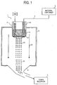
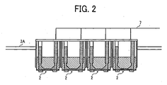
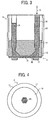


Classifications
-
- G—PHYSICS
- G03—PHOTOGRAPHY; CINEMATOGRAPHY; ANALOGOUS TECHNIQUES USING WAVES OTHER THAN OPTICAL WAVES; ELECTROGRAPHY; HOLOGRAPHY
- G03G—ELECTROGRAPHY; ELECTROPHOTOGRAPHY; MAGNETOGRAPHY
- G03G9/00—Developers
- G03G9/08—Developers with toner particles
- G03G9/0802—Preparation methods
- G03G9/0804—Preparation methods whereby the components are brought together in a liquid dispersing medium
-
- B—PERFORMING OPERATIONS; TRANSPORTING
- B01—PHYSICAL OR CHEMICAL PROCESSES OR APPARATUS IN GENERAL
- B01J—CHEMICAL OR PHYSICAL PROCESSES, e.g. CATALYSIS OR COLLOID CHEMISTRY; THEIR RELEVANT APPARATUS
- B01J2/00—Processes or devices for granulating materials, e.g. fertilisers in general; Rendering particulate materials free flowing in general, e.g. making them hydrophobic
- B01J2/02—Processes or devices for granulating materials, e.g. fertilisers in general; Rendering particulate materials free flowing in general, e.g. making them hydrophobic by dividing the liquid material into drops, e.g. by spraying, and solidifying the drops
- B01J2/04—Processes or devices for granulating materials, e.g. fertilisers in general; Rendering particulate materials free flowing in general, e.g. making them hydrophobic by dividing the liquid material into drops, e.g. by spraying, and solidifying the drops in a gaseous medium
-
- B—PERFORMING OPERATIONS; TRANSPORTING
- B05—SPRAYING OR ATOMISING IN GENERAL; APPLYING FLUENT MATERIALS TO SURFACES, IN GENERAL
- B05B—SPRAYING APPARATUS; ATOMISING APPARATUS; NOZZLES
- B05B17/00—Apparatus for spraying or atomising liquids or other fluent materials, not covered by the preceding groups
- B05B17/04—Apparatus for spraying or atomising liquids or other fluent materials, not covered by the preceding groups operating with special methods
- B05B17/06—Apparatus for spraying or atomising liquids or other fluent materials, not covered by the preceding groups operating with special methods using ultrasonic or other kinds of vibrations
- B05B17/0607—Apparatus for spraying or atomising liquids or other fluent materials, not covered by the preceding groups operating with special methods using ultrasonic or other kinds of vibrations generated by electrical means, e.g. piezoelectric transducers
- B05B17/0638—Apparatus for spraying or atomising liquids or other fluent materials, not covered by the preceding groups operating with special methods using ultrasonic or other kinds of vibrations generated by electrical means, e.g. piezoelectric transducers spray being produced by discharging the liquid or other fluent material through a plate comprising a plurality of orifices
- B05B17/0646—Vibrating plates, i.e. plates being directly subjected to the vibrations, e.g. having a piezoelectric transducer attached thereto
-
- B—PERFORMING OPERATIONS; TRANSPORTING
- B29—WORKING OF PLASTICS; WORKING OF SUBSTANCES IN A PLASTIC STATE IN GENERAL
- B29B—PREPARATION OR PRETREATMENT OF THE MATERIAL TO BE SHAPED; MAKING GRANULES OR PREFORMS; RECOVERY OF PLASTICS OR OTHER CONSTITUENTS OF WASTE MATERIAL CONTAINING PLASTICS
- B29B9/00—Making granules
- B29B9/10—Making granules by moulding the material, i.e. treating it in the molten state
-
- B—PERFORMING OPERATIONS; TRANSPORTING
- B29—WORKING OF PLASTICS; WORKING OF SUBSTANCES IN A PLASTIC STATE IN GENERAL
- B29B—PREPARATION OR PRETREATMENT OF THE MATERIAL TO BE SHAPED; MAKING GRANULES OR PREFORMS; RECOVERY OF PLASTICS OR OTHER CONSTITUENTS OF WASTE MATERIAL CONTAINING PLASTICS
- B29B9/00—Making granules
- B29B9/12—Making granules characterised by structure or composition
-
- G—PHYSICS
- G03—PHOTOGRAPHY; CINEMATOGRAPHY; ANALOGOUS TECHNIQUES USING WAVES OTHER THAN OPTICAL WAVES; ELECTROGRAPHY; HOLOGRAPHY
- G03G—ELECTROGRAPHY; ELECTROPHOTOGRAPHY; MAGNETOGRAPHY
- G03G9/00—Developers
- G03G9/08—Developers with toner particles
- G03G9/0819—Developers with toner particles characterised by the dimensions of the particles
-
- B—PERFORMING OPERATIONS; TRANSPORTING
- B29—WORKING OF PLASTICS; WORKING OF SUBSTANCES IN A PLASTIC STATE IN GENERAL
- B29B—PREPARATION OR PRETREATMENT OF THE MATERIAL TO BE SHAPED; MAKING GRANULES OR PREFORMS; RECOVERY OF PLASTICS OR OTHER CONSTITUENTS OF WASTE MATERIAL CONTAINING PLASTICS
- B29B9/00—Making granules
- B29B9/12—Making granules characterised by structure or composition
- B29B2009/125—Micropellets, microgranules, microparticles
Definitions
- the present invention relates to a method and an apparatus for preparing a toner used as developer developing electrostatic latent images in electrophotography, electrostatic recording and electrostatic printing, and a toner prepared thereby; and more particularly to improvement of uniform particle diameter dispersibility of the toner and productivity thereof.
- Developers for use in electrophotography, electrostatic recording and electrostatic printing, in their developing processes, are transferred to image bearers such as photoreceptors electrostatic latent images are formed on, transferred therefrom to a transfer medium such as a transfer paper, and fixed thereon.
- image bearers such as photoreceptors electrostatic latent images are formed on, transferred therefrom to a transfer medium such as a transfer paper, and fixed thereon.
- a two-component developer including a carrier and a toner, and a one-component developer without a carrier, such as a magnetic toner and a nonmagnetic toner are known.
- a pulverized toner is widely used, which is formed by kneading a toner binder such as styrene resins and polyester resins with a colorant, etc. upon application of heat, cooling the kneaded mixture to be solidified and pulverizing the solidified mixture.
- Japanese published unexamined application No. 7-152202 discloses a polymer solution suspension method of using a volume contraction. This method includes dispersing or dissolving toner constituents in a volatile solvent such as an organic solvent having a low boiling point to prepare a dispersion or a solution, emulsifying the dispersion or solution in an aqueous medium to form a droplet, and removing the volatile solvent.
- a volatile solvent such as an organic solvent having a low boiling point
- emulsifying the dispersion or solution in an aqueous medium to form a droplet
- the diversity of resins this method can use is wider than those of the suspension polymerization methods and emulsion polymerization condensation methods, and has an advantage of being capable of using a polyester resin effectively used for full-color images requiring transparency and smoothness.
- Japanese published unexamined application No. 57-201248 discloses a spray dry method having been known from long ago as a method of preparing a toner without using an aqueous medium. This atomizes and discharges a toner constituent solution or a toner constituent liquid with various atomizers, and dries to form particles. Therefore, this does not have problems o using an aqueous medium.
- particles prepared by the conventional spray granulation methods are coarse and large, and have a wide particle diameter distribution, resulting in deterioration of toner properties themselves.
- Japanese Patent No. 3786034 discloses a method and an apparatus forming a microscopic droplet of a toner constituent with a piezoelectric pulse, and drying and solidifying the microscopic droplet to form a toner. Further, Japanese Patent No. 3786035 discloses a method of forming a microscopic droplet thereof with a heat expansion in a nozzle, and drying and solidifying the microscopic droplet to form a toner.
- a method disclosed in Japanese published unexamined application No. 2006-293320 is that a nozzle is oscillated by expansion and contraction of a piezoelectric body as an oscillator to discharge a toner constituent fluid droplet at a constant frequency, and that the droplet is solidified to from a toner.
- Nozzles of civilian goods such as an inkjet recorder are typically subjected to a periodical maintenance to prevent the nozzles from being clogged or clear the nozzle.
- the nozzles discharging a toner constituent having high viscosity are much more frequently clogged than those of the inkjet recorders.
- a number of nozzles need to be located on a reservoir of the toner constituents to prepare a large amount of a toner.
- the sprayability of the other nozzles are adversely affected, resulting in uneven particle sizes of the resultant toner.
- an object of the present invention is to provide a method of stably preparing a toner having a uniform particle size.
- Another object of the present invention is to provide an apparatus stably preparing a toner having a uniform particle size using the method.
- a further object of the present invention is to provide a toner prepared by the method.
- the present invention contemplates the provision of a method of preparing a toner, comprising:
- the nozzle has an aperture discharging the droplet, having a circular or an ellipsoidal cross-sectional shape and cross-sectional area smaller than a cross-sectional area of another aperture contacting the toner constituent liquid.
- the present invention provides a method of stably preparing a toner having a uniform particle size. More particularly, the present invention relates to a method of preparing a toner, comprising:
- the nozzle has an aperture discharging the droplet, having a circular or an ellipsoidal cross-sectional shape and cross-sectional area smaller than a cross-sectional area of another aperture contacting the toner constituent liquid.
- Fig. 1 is a schematic view illustrating the apparatus for preparing a toner of the present invention.
- the toner preparation apparatus 1 includes a droplet spray unit 2 including a dripper and a reservoir, a particle former 3 solidifying a droplet of a toner constituent liquid discharged from the droplet spray unit 2 to form toner particles therebelow, a toner collector 4 collecting the toner particles T formed in the particle former 3, a toner reservoir 5 reserving the toner particles T, a material container 6 containing the toner constituent liquid, and a piping 7 having a feed pump 71 feeding the toner constituent liquid contained in the material container 6 to the droplet spray unit 2.
- Fig. 1 has only one droplet spray unit 2, however, plural, e.g., 100 to 1, 000 droplet spray units 2 are preferably located in line at an upper surface 3A of a drying tower forming the particle former 3 as shown in Fig. 2 .
- the toner constituent liquid is fed to each of the droplet spray units 2 through the piping 7 connected to the material container 6.
- the toner constituent liquid is automatically fed to the droplet spray units 2 while dripping, and may be fed thereto by an auxiliary pump 71.
- the droplet spray unit 2 as shown in Figs. 3 and 4 , includes a dripper 11 dripping and discharging a toner constituent liquid 10, wherein a toner constituent including at least a resin and a colorant is dispersed or dissolved, and a flow path member 13 including a liquid flow path 12 feeding the toner constituent liquid 10 to the dripper 11.
- the dripper 11 includes a thin film 16 including plural nozzles 15 and facing the liquid flow path 12 on a flow path member 13, and a circular ring-shaped electromechanical converter 17 located on the circumference of the thin film 16 as a mechanical oscillator oscillating the thin film 16.
- the thin film 16 is bonded to the flow path member 13 with a solder or a binder resin insoluble in the toner constituent liquid 10.
- the circular ring-shaped electromechanical converter 17 is bonded to the thin film 16 with a solder or a binder resin insoluble in the toner constituent liquid 10 as well.
- a drive voltage is applied to the electromechanical converter 17 from a drive circuit (not shown) through a lead wire.
- the thin film 16 is formed of a metallic plate having a thickness of from 5 to 500 ⁇ m.
- a nozzle 15 formed thereon has a liquid discharge aperture 18 having a cross-sectional area A smaller than a cross-sectional area B of an aperture contacting the liquid level 19, and is preferably tapered from the aperture contacting the liquid level 19 toward the liquid discharge aperture 18. This is for the toner constituent liquid 10 to discharge without stagnation so as not to clog the nozzle with solid particulate materials.
- the nozzle 15 can have the shape of a double-deck cylinder or cone because of having less fluid resistivity, which is suitable for discharging the toner constituent liquid 10 having high viscosity.
- the toner constituent liquid 10 includes particulate materials such as an organic pigment, an inorganic pigment and a release agent having an average particle diameter of from 100 to 200 nm.
- the liquid discharge aperture 18 preferably has a diameter not less than 10 times as large as the average particle diameter of the particulate materials, i.e., not less than 2 ⁇ m.
- a Pitch between the nozzles 15 preferably has a length not less than 3 times as long as a diameter of the liquid discharge aperture 18 to prevent the droplets from being combined after discharged.
- the aperture diameter of the nozzle 15 is a diameter when a true circle and a minor axis when an ellipse.
- the number of the plural nozzles is preferably from 2 to 3,000.
- the electromechanical converter 17 is not particularly limited, provided it can oscillate the thin film 16 at a constant frequency, and preferably, e.g., a bimorph piezoelectric body exciting a flexural oscillation.
- the piezoelectric body include piezoelectric ceramics such as lead zirconate titanate (LZT).
- LZT lead zirconate titanate
- the piezoelectric ceramics are typically layered because of having a small displacement.
- piezoelectric polymers such as polyvinylidenefluoride (PVDF) and single crystals such as quartz, LiNbO 3 , LiTaO 3 and KNbO 3 are preferably used.
- Each of a liquid feeding tube 20 feeding the toner constituent liquid 10 to a reservoir (the liquid flow path) 12 and an air bubble discharge tube 21 discharging air bubbles is connected to at least a part of the flow path member 13.
- the droplet spray unit 2 is located at the upper surface 3A of the drying tower forming the particle former 3.
- the droplet spray unit 2 may be located on the side surface or at the bottom thereof.
- a droplet forming mechanism by the dripper 11 will be explained, referring to Fig. 7 .
- the dripper 11 oscillates the thin film 16 with an electromechanical converter 17 as a mechanical oscillator formed in the shape of a ring along the circumference of to the thin film 16.
- Plural nozzles 15 are located in comparatively a large area having a diameter not less than 1 mm on the thin film 16 and droplets are stably formed and discharged from the plural nozzles 15.
- a simple circular thin film 16 having a fixed circumference 16A of as shown in Figs. 7(a) and 7(b) is oscillated, a basic oscillation has a displacement ⁇ L becoming maximum ( ⁇ Lmax) at the center of the circular thin film 16 as shown in Fig.
- the circular thin film 16 preferably oscillates having the circumference being a node without a node diametrically.
- Figs. 9 (a) and 9 (b) higher oscillation modes are known when oscillating the circular thin film 16. These modes concentrically have one or plural nodes in a circular thin film 16 and substantially has a symmetric deformed configuration in the radial direction.
- Fig. 10 when the circular thin film 16 has a convex center, a traveling direction of the droplet and the amplitude can be controlled.
- the toner constituent liquid 10 close to the plural nozzles 15 formed on the circular thin film 16 has a pressure Pa proportional to an oscillation speed Vm of the circular thin film 16.
- the oscillation speed Vm of the thin film 16 is a function of time t because of periodically varying with time, and can form various periodical variations such as a sine waveform and a rectangle waveform.
- every part of the thin film 16 has a different oscillation displacement and the oscillation speed Vm is also a function of a position coordinate on the thin film 16.
- An oscillation form of the thin film 16 is preferably a symmetric deformed configuration in the radial direction as mentioned above, and substantially a function of a radius r.
- a pressure proportional to an oscillation displacement speed having a distribution of the thin film 16 is generated and the toner constituent liquid 10 is discharged to a gas phase in accordance with a periodical change of the pressure. Since the toner constituent liquid 10 periodically discharged to the gas phase becomes spherical due to a difference of surface tensions between the liquid phase and the gas phase, the toner constituent liquid 10 is periodically dripped and discharged from the plural nozzles 15.
- Figs. 11 (a) and 11 (b) are schematic views illustrating the nozzle oscillating a thin film to discharge a droplet in the present invention.
- the thin film 16 oscillates bowing in the opposite direction of a reservoir 12 as shown in Fig. 11 (a) and in the direction thereof as shown in Fig. 11 (b) . Thereby, the thin film 16 oscillates to drip the toner constituent liquid 10 and discharge a droplet 23.
- the thin film 16 preferably has an oscillation frequency of from 20 kHz to 2.0 MHz, and more preferably from 50 to 500 kHz.
- the oscillation frequency not less than 20 kHz accelerates dispersion of a pigment and a wax in the toner constituent liquid 10.
- the dispersion of a pigment and a wax is more preferably accelerated when the toner constituent liquid 10 has a pressure not less than 10 kPa.
- the droplet has a larger diameter as the oscillation displacement in an area where the plural nozzles 15 of the thin film 16 are formed becomes larger.
- the oscillation displacement is small, a small droplet is formed or the toner constituent liquid 10 is not dripped.
- the plural nozzles 15 need to be located such that the thin film 16 has the most suitable oscillation displacement.
- the electromechanical converter 17 when the plural nozzles 15 are located such that the oscillation of the thin film 16 the electromechanical converter 17 generates in Fig. 8 or 9 has a ratio R ( ⁇ Lmax/ ⁇ Lmin) of a maximum ( ⁇ Lmax) to a minimum ( ⁇ Lmin) of the oscillation direction displacement not greater than 2.0 in an area the plural nozzles are formed, i.e., when the plural nozzles 15 are located in an area where R is not greater than 2.0, the droplet size variation can be in a range of toner particle sizes required to produce high-quality images.
- the toner constituent liquid 10 preferably has a sound pressure of from 10 kPa to 500 kPa, and more preferably from 10 kPa to 100 kPa to prevent the satellite particles from generating.
- the toner constituent liquid 10 including at least a resin and a colorant is fed into the reservoir 12 of the droplet spray unit 2.
- a drive waveform having a required drive frequency is applied to the electromechanical converter 17 of the dripper 11 to have a flexural oscillation.
- the flexural oscillation of the electromechanical converter 17 periodically oscillates the thin film 16.
- the oscillation of the thin film 16 periodically drip and discharge the toner constituent liquid 10 as a droplet 23 from the plural nozzles 15 into the particle former 3 as a solvent remover.
- the dripper 11 of the droplet spray unit 2 continuously discharges a number of the droplets 23 of the toner constituent liquid 10. Therefore, the toner preparation efficiency is more noticeably improved than that of toner preparation methods using conventional liquid discharge heads.
- the particle former 3 transports the droplet 23 discharged with a dry gas 24 streaming in the same direction as the dropping direction of the droplet 23 in the particle former 3 to remove the solvent therefrom and form a toner particle 25.
- the dry gas 24 has a dew point not higher than -10°C at atmospheric pressure.
- the dry gas 24 may be any gas capable of dying the droplet 23, such as air and nitrogen.
- the toner particle 25 formed in the particle former 3 is collected by the toner collector 4 on the downstream side and is retained in the toner reservoir 5 through a tube (not shown).
- the toner collector 4 has a cross-sectional shape having a tapered surface gradually shrinking from the entrance (droplet spray unit 2 side) to the exit.
- the toner particle 25 is transferred by a current of the dry gas 24 from an exit of the toner collector 4 to the toner reservoir 5.
- the toner particle 25 can be transferred from the toner collector 4 to the toner reservoir 5 with a pressure or suctioned thereby.
- the stream of the dry gas 24 is preferably a swirling current in terms of stably transferring the toner particle 25 with a centrifugal force.
- the toner collector 4, the tube (not shown) and the toner reservoir 5 are preferably formed of electroconductive materials and earthed. Further, the toner preparation apparatus 1 is preferably an explosion-proof apparatus.
- An entrance of the toner collector 4 has a discharger 41 temporarily neutralizing a charge of the toner particle 25 formed in the particle former 3 to prevent the toner particle 25 from adhering to the surface of the toner collector 4.
- a soft X-ray irradiator irradiating the toner particle 25 with a soft X-ray or a plasma irradiator irradiating the toner particle 25 with plasma can be used.
- the droplet 23 of the toner constituent liquid 10 may be dried by a cooler to form the toner particle 25. Further, the droplet 23 of the toner constituent liquid 10 may be passed through a feed path to form the toner particle 25, a charge thereof be temporarily neutralized by a discharger and the toner particle 25 be collected by the toner collector 4. The toner particle is discharged with a soft X-ray irradiation or a plasma irradiation.
- the droplet spray unit 2 including the thin film 16 the plural nozzles 15 are formed on and the circular ring-shaped electromechanical converter 17 oscillating the thin film 16, located on the circumference thereof drips and discharges the toner constituent liquid 10. Therefore, the toner particles 25 having more uniform particle diameter than ever are efficiently prepared.
- the liquid discharge aperture 18 having a cross-sectional area A smaller than a cross-sectional area B of the aperture contacting the liquid level 19 and ten times as large as an average particle diameter of solid dispersed particles in the toner constituent liquid 10 can stably and continuosly discharge the toner constituent liquid 10 having high-viscosity and including solid particles.
- the toner is prepared by the above-mentioned method using the above-mentioned apparatus 1, which has a sharp particle diameter distribution.
- the toner preferably has a ratio of a weight-average particle diameter to a number-average particle diameter thereof of from 1.00 to 1.05.
- the toner preferably has the weight-average particle diameter of from 1 to 20 ⁇ m.
- the toner of the present invention can easily be re-dispersed, i.e., floated due to electrostatic repulsion. Therefore, the toner can easily be transported to a developing area without conventional transport means.
- the toner can be transported even by an imperceptible airflow and a simple air pump can transport the toner to a developing area to be developed.
- An electrostatic latent image can be developed by so-called a power cloud development in quite good conditions without image forming disorder.
- the toner of the present invention can be used for conventional developing methods without problems. Carriers and members such as a developing sleeve are simply used as toner transporters, and do not need to have friction chargeability. Therefore, many other materials can be used therefor and durability thereof can largely be improved. In addition, more inexpensive materials can be used to reduce cost.
- toner materials for electrophotography can be used. Namely, a toner binder such as a styrene-acrylic resin, a polyester resin, a polyol resin and an epoxy resin is dissolved in an organic solvent to prepare a solution, and a colorant and a release agent is dispersed or dissolved therein to prepare a toner constituent liquid. Then, the toner constituent liquid is finely dripped, dried and solidified to prepare a toner particle of the present invention.
- the above-mentioned materials are melted and kneaded upon application of heat to prepare a kneaded mixture, and the kneaded mixture is dissolved or dispersed in a solvent to prepare a toner constituent liquid. Then, the toner constituent liquid is also finely dripped, dried and solidified to prepare a toner particle 25 of the present invention.
- the toner materials includes at least a resin and a colorant, and optionally other components such as a carrier and a wax.
- the resin includes at least a binder resin.
- the binder resin include, but are not limited to, conventionally-used resins such as a vinyl polymers including styrene monomers, acrylic monomers or methacrylic monomers, or copolymers including two or more of the monomers; polyester polymers; polyol resins; phenol resins; silicone resins; polyurethane resins; polyamide resins; furan resins; epoxy resins; xylene resins; terpene resins; coumarone-indene resins; polycarbonate resins; petroleum resins; etc.
- styrene monomers include styrenes or their derivatives such as styrene, o-methylstyrene, m-methylstyrene, p-methylstyrene, p-phenylstyrene, p-ethylstyrene, 2,4-dimethylstyrene, p-n-butylstyrene, p-tert-butylstyrene, p-n-hexylstyrene, p-n-hexylstyrene, p-n-octylstyrene, p-n-nonylstyrene, p-n-decylstyrene, p-n-dodecylstyrene, p-methoxystyrene, p-chlorostyrene, 3,4-dochlorostyrne,
- acrylic monomers include an acrylic acid or their esters such as methylacrylate, ethylacrylate, n-butylacrylate, isobutylacrylate, n-octylacrylate, n-dodecylacrylate, 2-ethylhexylacrylate, stearylacrylate, 2-chloroethylacrylate and phenylacrylate.
- acrylic acid or their esters such as methylacrylate, ethylacrylate, n-butylacrylate, isobutylacrylate, n-octylacrylate, n-dodecylacrylate, 2-ethylhexylacrylate, stearylacrylate, 2-chloroethylacrylate and phenylacrylate.
- the methacrylic monomers include a methacrylic acid or their esters such as a methacrylic acid, methylmethacrylate, ethylmethacrylate, propylmethacrylate, n-butylmethacrylate, isobutylmethacrylate, n-octylmethacrylate, n-dodecylmethacrylate, 2-ethylhexylmethacrylate, stearylmethacrylate, phenylmethacrylate, dimethylaminoethylmethacrylate and diethylaminoethylmethacrylate.
- a methacrylic acid or their esters such as a methacrylic acid, methylmethacrylate, ethylmethacrylate, propylmethacrylate, n-butylmethacrylate, isobutylmethacrylate, n-octylmethacrylate, n-dodecyl
- the vinyl polymer or copolymer of the binder resin may have a crosslinked structure formed by a crosslinker having 2 or more vinyl groups.
- the crosslinker include aromatic divinyl compounds such as divinylbenzene and divinylnaphthalene; diacrylate compounds bonded with an alkyl chain, such as ethyleneglycoldiacrylate, 1,3-butyleneglycoldiacrylate, 1,4-butanedioldiacrylate, 1,5-pentanedioldiacrylate, 1,6-hexanedildiacrylate, neopentylglycoldiacrylate or their dimethacrylates; and diacrylate compounds bonded with an alkyl chain including an ester bond, such as diethyleneglycoldiacrylate, triethyleneglycoldiacrylate, tetraethyleneglycoldiacrylate, polyethyleneglycoldiacrylate#400, polyethyleneglycoldiacrylate#600, dipropyleneglycoldiacryl
- Polyester diacrylates include a product named MANDA from NIPPON KAYAKU CO., LTD.
- multifunctional crosslinker examples include pentaerythritoltriacrylate, trimethylolethanetriacrylate, trimethylolpropanetriacrylate, tetramethylolmethanetetraacrylate, oligoesteracrylate and their methacrylates, triallylcyanurate and triallyltrimellitate.
- the toner preferably includes the crosslinker in an amount of 0.001 to 10 parts by weight, more preferably from 0.03 to 5 parts by weight based on total weight of the monomer.
- the aromatic divinyl compounds particularly the divinylbenzene and the diacrylate compounds bonded with a bonding chain including an aromatic group and an ether bond are preferably used in terms of the fixability and offset resistance of the resultant toner.
- styrene copolymers and styrene-acrylic copolymers are more preferably used.
- a polymerization initiator used for preparing the vinyl polymer or copolymer include azo polymerization initiators such as2,2'-azobisisobutyronitrile, 2,2'-azobis(4-methoxy-2,4-dimethylvaleronitrile), 2,2'-azobis(2,4-dimethylvaleronitrile), 2,2'-azobis(2-methylbutyronitrile), dimethyl-2,2'-azobisisobutylate, 1,1'-azobis(cyclohexanecarbonitrile), 2-(carbamoylazo)-isobutyronitrile, 2,2'-azobis(2,4,4-trimethylpentane), 2-phenylazo-2',4'-fimethyl-4'-methoxyvaleronitrile and 2,2'-azobis(2-methylpropane); ketone peroxides such as methyl ethyl ketone peroxide, acetylacetone peroxide and cyclohexanone per
- the binder resin when the binder resin is selected from styrene-acrylic resins, the binder resin preferably includes elements soluble with tetrahydrofuran (THF) , having at least one peak in a range of 3, 000 to 50, 000 (number-average molecular weight) and at one peak in a range not less than 100,000 in a molecular weight distribution by GPC thereof in terms of the fixability, offset resistance and storage stability of the resultant toner.
- THF-soluble elements having a molecular weight not greater than 100, 000 is preferably from 50 to 90% by weight based on total weight of the THF-soluble elements.
- the THF-soluble elements preferably have a main peak in a molecular weight range of from 5,000 to 30,000, and more preferably from 5,000 to 20,000.
- the binder resin is selected from vinyl polymers such as styrene-acrylic resins
- the binder resin preferably has an acid value of from 0.1 to 100 mg KOH/g, more preferably from 0.1 to 70 mg KOH/g, and much more preferably from 0.1 to 50 mg KOH/g.
- polyester polymers include the following materials.
- bivalent alcohol examples include diols such as ethyleneglycol, propyleneglycol, 1,3-butanediol, 1,4-butanediol, 2,3-butanediol, 1,4-butenediol, diethyleneglycol, triethyleneglycol, 1,5-pentanediol, 1,6-hexanediol, neopentylglycol, 2-ethyl-1,3-hexanediol, and diols formed by polymerizing hydrogenated bisphenol A or bisphenol A with cyclic ethers such as an ethylene oxide and a propylene oxide.
- alcohol having 3 valences or more is preferably used together.
- polyalcohol having 3 or more valences include sorbitol, 1,2,3,6-hexanetetrol, 1,4-sorbitan, pentaerythritol, dipentaerythritol, tripentaerythritol, 1,2,4-butanetriol, 1,2,5-pentanetriol, glycerol, 2-methylpropanetriol, 2-methyl-1,2,4-butanetriol, trimethylolethane, trimethylolpropane, 1,3,5-trihydroxybenzene, etc.
- acids forming the polyester polymers include benzene dicarboxylic acids or their anhydrides such as a phthalic acid, an isophthalic acid and a terephthalic acid; alkyl dicarboxylic acids or their anhydrides such as a succinic acid, an adipic acid, a sebacic acid and an azelaic acid; unsaturated diacids such as a maleic acid, a citraconic acid, an itaconic acid, an alkenylsuccinic acid, a fumaric acid and a mesaconic acid; and unsaturated diacid anhydrides such as a maleic acid anhydride, a citraconic acid anhydride, an itaconic acid anhydride and an alkenylsuccinic acid anhydride; etc.
- benzene dicarboxylic acids or their anhydrides such as a phthalic acid, an isophthalic acid and a terephthalic acid
- polycarboxylic acids having 3 or more valences include a trimellitic acid, a pyromellitic acid, a 1,2,4-benzenetricarboxylic acid, a1,2,5-benzenetricarboxylic acid, a 2,5,7-naphthalenetricarboxylic acid, a 1,2,4-naphthalenetricarboxylic acid, a 1,2,4-butanetricarboxylic acid, a 1,2,5-hexanetricarboxylic acid, a 1,3-dicarboxyl-2-methyl-methylenecarboxypropane, tetra(methylenecarboxyl)methane, 1,2,7,8-octantetracarboxylic acids, empol trimer or their anhydrides, or those partially replaced with lower alkyl esters , etc.
- the binder resin when the binder resin is a polyester resin, the binder resin preferably includes elements soluble with tetrahydrofuran (THF), having at least one peak in a range of 3,000 to 50,000 (number-average molecular weight) in a molecular weight distribution by GPC thereof in terms of the fixability and offset resistance of the resultant toner.
- THF-soluble elements having a molecular weight not greater than 100, 000 is preferably from 60 to 100% by weight based on total weight of the THF-soluble elements.
- the THF-soluble elements preferably have a main peak in a molecular weight range of from 5,000 to 20,000.
- the binder resin when the binder resin is a polyester resin, the binder resin preferably has an acid value of from 0.1 to 100 mgKOH/g, more preferably from 0.1 to 70 mgKOH/g, and most preferably from 0.1 to 50 mgKOH/g.
- the molecular weight distribution of the binder resin is measured by gel permeation chromatography (GPC) using THF as a solvent.
- resins including monomers reactable therewith can be used.
- the monomers forming the polyester resin, reactable with the vinyl polymer include unsaturated dicarboxylic acids or their anhydrides such as a phthalic acid, a maleic acid, a citraconic acid and an itaconic acid.
- Specific examples of the monomers forming the vinyl polymer include monomers having a carboxyl group or a hydroxy group, and an acrylic acid or ester methacrylates.
- the united resins preferably includes resins having an acid value of from 0.1 to 50 mgKOH/g in an amount of 60% by weight.
- the acid value of the binder resin can be measured according to JIS K-0070 as follows.
- the binder resin and constituents including the binder resin of the toner preferably has a glass transition temperature of from 35 to 80°C, and more preferably from 40 to 75°C in terms of the storage stability of the resultant toner.
- a glass transition temperature of from 35 to 80°C, and more preferably from 40 to 75°C in terms of the storage stability of the resultant toner.
- magnetic materials for use in the present invention include (1) magnetic iron oxides such as magnetite, maghematite and ferrite and iron oxides including other metal oxides; (2) metals such as iron, cobalt and nickel or their metal alloys with metals such as aluminum, cobalt, copper, lead, magnesium, tin, zinc, antimony, beryllium, bismuth, cadmium, calcium, manganese, selenium, titanium, tungsten and vanadium; and (3) their mixtures.
- magnetic iron oxides such as magnetite, maghematite and ferrite and iron oxides including other metal oxides
- metals such as iron, cobalt and nickel or their metal alloys with metals such as aluminum, cobalt, copper, lead, magnesium, tin, zinc, antimony, beryllium, bismuth, cadmium, calcium, manganese, selenium, titanium, tungsten and vanadium
- metals such as iron, cobalt and nickel or their metal alloys with metals such as aluminum,
- magnetic iron oxides such as magnetite, maghematite and ferrite including a heterogeneous element or their mixtures can also be used.
- the heterogeneous element include lithium, beryllium, boron, magnesium, aluminum, silicon, phosphorus, germanium, zirconium, tin, sulfur, calcium, scandium, titanium vanadium, chrome, manganese, cobalt, nickel, copper, zinc, gallium, etc.
- magnesium, aluminum, silicon, phosphorus or zirconium is preferably used.
- the heterogeneous element may be taken in a crystal lattice of the iron oxide or therein as an oxide. Alternatively, the heterogeneous element may be present on the surface thereof as an oxide or a hydroxide. The heterogeneous element is preferably included therein as an oxide .
- the heterogeneous element can be taken in a magnetic material by mixing a salt thereof when preparing the magnetic material and performing a pH control.
- the heterogeneous element can be separated out on the surface of a magnetic material by performing the pH control or adding the salt thereof and performing the pH control after preparing the magnetic material.
- the toner preferably includes the magnetic material in an amount of from 10 to 200 parts by weight, and more preferably from 20 to 150 parts by weight per 100 parts by weight of the binder resin.
- the magnetic material preferably has a number-average particle diameter of from 0.1 to 2 ⁇ m, and more preferably from 0.1 to 0.5 ⁇ m. The number-average particle diameter can be determined by measuring a photograph thereof, zoomed by a transmission electron microscope, with a digitizer, etc.
- the magnetic material preferably has a coercivity of from 2 to 150 Oe, a saturated magnetization of from 50 to 200 emu/g and a residual magnetization of from 2 to 20 emu/g when applied with 10k Oe.
- the magnetic material can be used as a colorant.
- colorants for use in the present invention include any known dyes and pigments such as carbon black, Nigrosine dyes, black iron oxide, NAPHTHOL YELLOW S, HANSA YELLOW (10G, 5G and G) , Cadmium Yellow, yellow iron oxide, loess, chrome yellow, Titan Yellow, polyazo yellow, Oil Yellow, HANSA YELLOW (GR, A, RN and R), Pigment Yellow L, BENZIDINE YELLOW (G and GR), PERMANENT YELLOW (NCG), VULCAN FAST YELLOW (5G and R), Tartrazine Lake, Quinoline Yellow Lake, ANTHRAZANE YELLOW BGL, isoindolinone yellow, red iron oxide, red lead, orange lead, cadmium red, cadmium mercury red, antimony orange, Permanent Red 4R, Para Red, Fire Red, p-chloro-o-nitroaniline red, Lithol Fast Scarlet G, Brilliant Fast Scarlet, Brilliant Carmine BS
- the toner preferably includes the colorant in an amount of from 1 to 15 % by weight, and more preferably from 3 to 10 % by weight.
- the colorant for use in the present invention can be used as a masterbatch when combined with a resin.
- the resin used in the masterbatch or used with the masterbatch include the modified and unmodified polyester resins mentioned above; styrene polymers and substituted styrene polymers such as polystyrene, poly-p-chlorostyrene and polyvinyltoluene; styrene copolymers such as styrene-p-chlorostyrene copolymers, styrene-propylene copolymers, styrene-vinyltoluene copolymers, styrene-vinylnaphthalene copolymers, styrene-methyl acrylate copolymers, styrene-ethyl acrylate copolymers, styrene-butyl acrylate copolymers, styrene-oct
- the masterbatch can be prepared by mixing and kneading a resin and a colorant upon application of high shearing stress thereto.
- an organic solvent is preferably used to increase interactions between the colorant and the resin.
- flushing methods wherein an aqueous paste including a colorant is mixed with a resin solution of an organic solvent to transfer the colorant to the resin solution and then the aqueous liquid and organic solvent are separated and removed, is preferably used because the resultant wet cake of the colorant can be used as it is.
- a three roll mill is preferably used for kneading the mixture upon application of high shearing stress.
- the toner preferably includes the colorant in an amount of from 0.1 to 20 parts by weight per 100 parts by weight of the binder resin.
- the masterbatch preferably includes a resin having an acid value not greater than 30 mg KOH/g and an amine value of from 1 to 100 and a colorant dispersed therein, and more preferably includes a resin having an acid value not greater than 20 mg KOH/g and an amine value of from 10 to 50 and a colorant dispersed therein.
- the acid value is greater than 30 mg KOH/g, the chargeability of the resultant toner occasionally deteriorates due to high humidity and the colorant is insufficiently dispersed in the masterbatch occasionally.
- the amine value is less than 1 and greater than 100, the colorant is insufficiently dispersed in the masterbatch occasionally.
- the acid value is measured by the method disclosed in JIS K0700 and the amine value in JIS K7237.
- a dispersant preferably has high compatibility with a binder resin in terms of pigment dispersibility.
- Specific examples of marketed products thereof include AJISPER PB821 and AJISPER PB822 from Ajinomoto Fine-Techno Co., Inc.; Disperbyk-2001 from BYK-Chemie GmbH; and EFKA-4010 from EFKA ADDITIVES.
- a toner preferably includes the dispersant in an amount of from 0.1 to 10% by weight based on total weight of the colorant. When less than 0.1% by weight, the pigment is insufficiently dispersed occasionally. When greater than 10% by weight, the chargeability of the resultant toner occasionally deteriorates due to high humidity.
- the dispersant preferably has a weight-average molecular weight, i.e., a molecular weight at a maximum main peak in the gel permeation chromatography of a styrene-converted weight, of from 500 to 100,000, more preferably from 3,000 to 100,000, furthermore preferably from 5, 000 to 50,000, and most preferably form 5, 000 to 30,000 in terms of pigment dispersibility.
- a weight-average molecular weight i.e., a molecular weight at a maximum main peak in the gel permeation chromatography of a styrene-converted weight, of from 500 to 100,000, more preferably from 3,000 to 100,000, furthermore preferably from 5, 000 to 50,000, and most preferably form 5, 000 to 30,000 in terms of pigment dispersibility.
- the dispersant has high polarity, resulting in occasional dispersibility deterioration of the colorant.
- greater than 100,000 the dispersant has high affinity with a solvent, resulting in occasional dispersibility deterioration
- the toner of the present invention may be mixed with a carrier and used as a two-component developer.
- Conventional carriers such as ferrite and magnetite, and resin-coated carriers can be used.
- the resin-coated carrier is formed of a carrier core material and a coating material, i.e., a resin coating the surface of the carrier core material.
- the resin examples include styrene-acrylic resins such as a styrene-esteracrylate copolymer and a styrene-estermethacrylate copolymer; acrylic resins such as an esteracrylate copolymer and an estermethacrylate copolymer; fluorine-containing resins such as polytetrafluoroethylene, monochlorotrifluoroethylene polymer and polyvinylidene-fluoride; a silicone resin; a polyester resin; a polyamide resin; polyvinylbutyral; and an aminoacrylate resin.
- styrene-acrylic resins such as a styrene-esteracrylate copolymer and a styrene-estermethacrylate copolymer
- acrylic resins such as an esteracrylate copolymer and an estermethacrylate copolymer
- fluorine-containing resins such as polytetrafluoroethylene,
- any resins such as an ionomer resin and a polyphenylenesulfide resin usable as a coating material for a carrier can be used. These can be used alone or in combination.
- a binder carrier core wherein a magnetic powder is dispersed in a resin, can also be used.
- Methods of coating a resin coating material on the surface of the carrier core include dissolving or suspending a resin in a solvent to prepare a coating solution and coating the coating solution thereon; and simply mixing a resin and the carrier core in the state of powders.
- the resin-coated carrier preferably includes a resin coating material in an amount of from 0.01 to 5% by weight, and more preferably from 0.1 to 1% by weight.
- a magnetic material is coated with a coating mixture including two or more materials
- a styrene-methylmethacrylate copolymer, mixtures of fluorine-containing resins and styrene copolymers or a silicone resin is preferably used.
- the silicone resin is more preferably used.
- the mixtures of fluorine-containing resins and styrene copolymers include a mixture of polyvinylidene fluoride and a styrene-methylmethacrylate copolymer; and a mixture of a polytetrafluoroethylene and a styrene-methylmethacrylate copolymer; a mixture of vinylidene fluoride-tetrafluoroethylene copolymer (10/90 to 90/10), a styrene-acrylate2-ethylhexyl copolymer (10/90 to 90/10) and a styrene-acrylate2-ethylhexyl-methylmethacrylate copolymer (20 to 60/5 to 30/10/50).
- Specific examples of the silicone resin include a nitrogen-containing silicone resin and a modified silicone resin formed from a reaction between a nitrogen-containing silane coupling agent and a silicone resin.
- Magnetic materials for the carrier core include iron oxides such as ferrite, iron-excess ferrite, magnetite and ⁇ -iron oxide; an metals such as iron, cobalt, nickel and their metal alloys. Specific examples of elements included therein include iron, cobalt, nickel, aluminum, copper, lead, magnesium, tin, zinc, antimony, beryllium, bismuth, calcium, manganese, selenium, titanium, tungsten, vanadium, etc. Copper-zinc-iron ferrite mainly including copper, zinc and iron; and manganese-magnesium-iron ferrite mainly including manganese, magnesium and iron are preferably used.
- the carrier preferably has a resistivity of from 10 6 to 10 10 ⁇ cm by controlling the concavities and convexities on the surface thereof an amount of a resin coated thereon.
- the carrier preferably has a particle diameter of from 4 to 200 ⁇ m, more preferably from 10 to 150 ⁇ m, and much more preferably from 20 to 100 ⁇ m.
- the resin-coated carrier preferably has a 50% particle diameter of from 20 to 70 ⁇ m.
- the two-component developer preferably includes the toner of the present invention in an amount of from 1 to 200 parts by weight, and more preferably from 2 to 50 parts by weight per 100 parts by weight of the carrier.
- the toner of the present invention may include a wax besides a binder resin and a colorant.
- Any known waxes can be used, and specific examples thereof include aliphatic hydrocarbon waxes such as low-molecular-weight polyethylene, low-molecular-weight polypropylene, a polyolefin wax, a microcrystalline wax, a paraffin wax and a sasol wax; aliphatic hydrocarbon wax oxides such as polyethylene oxide wax or their block copolymers; plant waxes such as a candelilla wax, a carnauba wax, a Japan wax, and a jojoba wax; animal waxes such as a bees wax, a lanolin and a whale wax; mineral waxes such as an ozokerite, a ceresin and a petrolatum; waxes mainly including fatty ester such as a montanic acid ester wax and a mosquito star wax; and waxes having partially or wholly deacidified fatty este
- the wax further include saturated straight-chain fatty acids such as a palmitic acid, a stearic acid, a montanic acid and a straight-chain alkyl carboxylic acid having a straight-chain alkyl group; unsaturated fatty acids such as an eleostearic acid; saturated alcohols such as stearyl alcohol, behenyl alcohol, ceryl alcohol, mesilyl alcohol and long-chain alkyl alcohol; polyalcohols such as sorbitol; fatty acid amides such as linoleic amide, olefinic amide and lauric amide; saturated fatty acid bismaides such as methylenebisamide caprate, lauric ethylenebisamide and stearic hexamethylenebisamide; unsaturated fatty acid amides such as oleic ethylenebisamide, oleic hexamethylenebisamide, adipic N, N'-dioleylamide and sebacic N, N'-dioleyl
- Preferred waxes include polyolefin formed by radically polymerizing olefin under high pressure; polyolefin formed by refining a low-molecular-weight byproduct when polymerizing high-molecular-weight polyolefin; polyolefin formed by polymerizing olefin with a catalyst such as a Ziegler catalyst and a metallocene catalyst under low pressure; polyolefin formed by polymerizing olefin using a radiation, an electromagnetic ray or light; low-molecular-weight polyolefin formed by pyrolyzing high-molecular-weight polyolefin; a paraffin wax; a microcrystalline wax; a Fischer-Tropsh wax; synthetic hydrocarbon waxes synthesized by a synthol method, a hydronalium call method, etc.; synthetic waxes having a monomer having a carbon atom; hydrocarbon waxes having a functional group such as a hydroxyl group or a carboxyl
- waxes having sharper molecular weight distributions after subjected to a press sweating process, a solvent process, a recrystallization process, a vacuum distillation process, a supercritical gas extraction process or a solution crystallization process are preferably used.
- waxes, wherein low-molecular-weight fatty acids, low-molecular-weight solid alcohols, low-molecular-weight solid compounds and other impurities are removed from these waxes are preferably used as well.
- the wax preferably has a melting point of from 70 to 140°C, and more preferably from 70 to 120°C to balance the fixability and offset resistance of the resultant toner.
- a melting point of from 70 to 140°C, and more preferably from 70 to 120°C to balance the fixability and offset resistance of the resultant toner.
- 70°C blocking resistance thereof tends to deteriorate.
- higher than 140°C the offset resistance thereof is difficult to develop.
- combinations of two or more waxes can develop plasticizability and releasability of a wax at the same time.
- a wax having plasticizability has a low melting point, or a branched-chain or a polar group on its molecular structure.
- a wax having releasability has a low melting point, or a straight-chain or nonpolar group without a functional group on its molecular structure.
- Specific examples of the combinations include a combination of two ore more waxes having differences of melting point of from 10 to 100°C; and a combination of polyolefin and graft-modified polyolefin.
- combinations of a low-melting-point wax relatively having plasticizability and a high-melting-point wax relatively having releasability are preferably used.
- the melting points preferably have a difference from 10 to 100°C to effectively develop their separate functions.
- At least one of the waxes preferably has a melting point of from 70 to 120°C, and more preferably from 70 to 100°C to exert the functional separation effect.
- Waxes having branched-chain structures, polar groups such as functional groups, or waxes modified with components different from their main components relatively exert their plasticizabilities.
- waxes having straight-chain structure, nonpolar groups without functional groups, or unmodified waxes relatively exert their releasabilities.
- Preferred combinations of the waxes include a combination of a polyethylene homopolymer or copolymer primarily consisting of ethylene and a polyolefin homopolymer or copolymer primarily consisting of olefin besides ethylene; a combination of polyolefin and graft-modified polyolefin; a combination of an alcohol wax, a fatty acid wax or an ester wax and a hydrocarbon wax; a combination of a Fischer-Tropsh wax or a polyolefin wax and a paraffin wax or a microcrystalline wax; a combination of a Fischer-Tropsh wax and a polyolefin wax; a combination of a paraffin wax and a microcrystalline wax; a carnauba wax, a candelilla wax, a rice wax or a montan wax and a hydrocarbon wax.
- the wax preferably has an endothermic peak in a range of from 70 to 110°C, and further a maximum peak therein when measured by a DSC method to balance the storage stability and fixability of the resultant toner.
- the toner of the present invention preferably includes the waxes in an amount of from 0.2 to 20 parts by weight, and more preferably from 0.5 to 10 parts by weight per 100 parts by weight of a binder resin.
- the melting point of the wax is the maximum endothermic peak when measured by a DSC method.
- the endothermic peak of the wax or toner is preferably measure by a high-precision inner-heat input-compensation differential scanning calorimeter. The measurement method is based on ASTM D3418-82. A DSC curve measured when the temperature is increased at 10°C/min after increasing and decreasing the temperature is used.
- the toner of the present invention may include a fluidity improver.
- the fluidity improver is added to the surface thereof to improve the fluidity thereof.
- Specific examples thereof include fluorine-containing resin powders such as carbon black, a vinylidene fluoride fine powder and a polytetrafluoroethylene fine powder; a silica fine powder such as a wet method silica and a dry method silica; a titanium oxide fine powder; an alumina fine powder; and a surface-treated silica, a surface-treated titanium oxide and a surface-treated alumina with a silane coupling agent, a titanium coupling agent or a silicone oil.
- the silica fine powder, titanium oxide fine powder and alumina fine powder are preferably used.
- the surface-treated silica with a silane coupling agent or a silicone oil is more preferably used.
- the fluidity improver preferably has an average primary particle diameter of from 0.001 to 2 ⁇ m, and more preferably from 0.002 to 0.2 ⁇ m.
- Preferred silica fine powders include a fine powder prepared by vapor-phase oxidizing a silicon halogen compound, i.e. a dry method silica or a fumed silica.
- Specific examples of the marketed silica fine powders include AEROSIL-130, -300, -380, -TT600, -MOX170, -MOX80 and -COK84 from NIPPON AEROSIL CO., LTD.; Ca-O-SiL-M-5, -MS-7, -MS-75, -HS-5 and -EH-5 from Cabot Corp.; Wacker HDK-N20, -V15, -N20E, -T30 and -T40 from WACKER-CHEMIEGMBH; D-CFineSilica from Dow Corning Corp.; and Fansol from Fransil.
- the silica fine powder prepared by vapor-phase oxidizing a silicon halogen compound is preferably hydrophobized.
- the hydrophobized silica fine powder preferably has a hydrophobicity of from 30 to 80% when measured by a methanol titration method.
- the silica fine powder is chemically or physically hydrophobized with an organic silicon compound.
- Specific examples thereof include hydroxypropyltrimethoxysilane, phenyltrimethoxysilane, n-hexadecyltrimethoxysilane, n-octadecyltrimethoxysilane, vinylmethoxysilane, vinyltriethoxysilane, vinyltriacetoxysilane, dimethylvinylchlorosilane, divinylchlorosilane, ⁇ -methacryloxypropyltrimethoxysilane, hexamethyldisilane, trimethylsilane, trimethylchlorosilane, dimethyldichlorosilane, methyltrichlorosilane, allyldimethylchlorosilane, allylphenyldichlorosilane, benzyldimethylchlorosilane, bromomethyldimethylchlorosilane, ⁇ -chlorethyltrichlorosilane, ⁇ -chlor
- the fluidity improver preferably has a specific surface area not less than 30 m 2 /g, and more preferably from 60 to 400 m 2 /g when measured by a BET nitrogen absorption method.
- the fluidity improver preferably has a specific surface area not less than 20 m 2 /g, and more preferably from 40 to 300 m 2 /g.
- the fluidity improver is preferably included in a toner in an amount of from 0.03 to 8 parts by weight per 100 parts by weight of the toner.
- various metal soaps, fluorine-containing surfactants and dioctylphthalate may optionally be included in the toner of the present invention for the purpose of protecting a photoreceptor or a carrier; improving the cleanability thereof; controlling heat, electrical and physical properties thereof; controlling the resistivity thereof; controlling the softening point thereof; and improving the fixability thereof; etc.
- an electroconductivity imparting agent inorganic fine powders such as tin oxide, zinc oxide, carbon black, antimony oxide, titanium oxide, aluminum oxide and alumina may optionally be included therein.
- the inorganic fine powders may optionally be hydrophobized.
- Lubricants such aspolytetrafluoroethylene, zinc stearate and polyvinylidene-fluoride; abrasives such as cesium oxide, silicon carbonate and strontium titanate; caking inhibitors; and developability improvers such as white and black particulate materials having polarities reverse to that of a toner can also be used in a small amount.
- the additives preferably treated with various agents such as silicone varnishes, various modified silicone varnishes, silicone oils, various modified silicone oils, silane coupling agents, silane coupling agents having functional groups and other organic silicon compounds for the purpose of controlling the charge amount of the resultant toner.
- a developer can be prepared by the following method.
- the inorganic particulate materials such as a hydrophobic silica fine powder may be added to a developer to increase the storage stability, developability and transferability thereof.
- a typical powder mixer is used to mix external additives, and preferably includes a jacket and is capable of controlling inner temperature.
- the external additive may gradually be added in the mixer or on the way of mixing to change the history of stressing the external additive. As a matter of course, the number of rotations, rotation speed, mixing time and mixing temperature of the mixer may be changed. A large stress may be applied to the external additive at the beginning, and comparatively a small stress is applied thereto then, or vice versa.
- Specific examples of the mixers include V-type Mixer, Rocking Mixer, Loedge Mixer, Nauter Mixer and Henschel Mixer.
- toner constituents such as a binder resin and a colorant are melted and kneaded upon application of heat, cooled and pulverized
- the shape of the toner is mechanically controlled by Hybridizer or Machanofusion.
- the toner constituents are dissolved and dispersed in a solvent capable of dissolving the binder resin, and the solvent is removed from the dispersion by a spray drier to prepare a spherical toner.
- a spherical toner can also be prepared by being heated in an aqueous medium.
- Inorganic particulate materials can externally be added to the toner of the present invention to supplement the chargeability thereof.
- specific examples of the inorganic particulate material include silica, alumina, titanium oxide, barium titanate, magnesium titanate, calcium titanate, strontium titanate, zinc oxide, tin oxide, quartz sand, clay, mica, sand-lime, diatom earth, chromium oxide, cerium oxide, red iron oxide, antimony trioxide, magnesium oxide, zirconium oxide, barium sulfate, barium carbonate, calcium carbonate, silicon carbide, silicon nitride, etc.
- the inorganic particulate material preferably has a primary particle diameter of from 2 to 5 ⁇ m, and more preferably from 5 to 500 ⁇ m.
- the inorganic particulate material preferably has a specific surface area of from 20 to 500 m 2 /g when measured by a BET nitrogen absorption method.
- the inorganic particulate material is preferably included in a toner in an amount of from 0.01 to 5% by weight, and more preferably from 0.01 to 2.0% by weight based on total weight of the toner.
- polystyrene, ester methacrylate and ester acrylate copolymers formed by soap-free emulsifying polymerization, suspension polymerization and dispersion polymerization; polycondensated particulate materials such as silicone, benzoguanamine and nylon; and polymerized particulate materials formed of thermosetting resins can also be used.
- the external additives can be treated with a surface treatment agent to increase the hydrophobicity to prevent deterioration of fluidity and chargeability even in an environment of high humidity.
- the surface treatment agent examples include a silane coupling agent, a sililating agent, a silane coupling agent having an alkyl fluoride group, an organic titanate coupling agent, an aluminum coupling agent a silicone oil and a modified silicone oil.
- the toner of the present invention may include a cleanability improver for removing a developer remaining on a photoreceptor and a first transfer medium after transferred.
- the cleanability improver include fatty acid metallic salts such as zinc stearate, calcium stearate and stearic acid; and polymer particulate materials prepared by a soap-free emulsifying polymerization method such as a polymethylmethacrylate particulate material and a polystyrene particulate material.
- the polymer particulate materials comparatively have a narrow particle diameter distribution and preferably have a volume-average particle diameter of from 0.01 to 1 ⁇ m.
- photoreceptors such as an organic photoreceptor, am amorphous silica photoreceptor, a selenium photoreceptor and a zinc oxide photoreceptor can be used in the present invention.
- a toner constituent dispersion including a binder resin, the colorant dispersion and the wax dispersion was prepared. 100 parts of a polyester resin, each 30 parts of the colorant dispersion and thee wax dispersion, and 840 parts of ethylacetate were agitated for 10 min to be uniformly dispersed by a mixer having an agitation blade to prepare a dispersion. The pigment and wax did not aggregate with the solvent. The dispersion had a electroconductivity of 1.8 x 10 -7 S/m.
- the dispersion was fed into the dripper 11.
- the thin film 16 was formed of a nickel plate having an outer diameter of 8.0 mm and a thickness of 20 ⁇ m, on which tapered nozzles 15 having a diameter of 50 ⁇ m at aperture contacting the liquid level 19 and a diameter of 10 ⁇ m at the liquid discharge aperture 18 were formed by electroforming.
- the nozzles were formed in the shape of a houndstooth check at the center of the plate in an area having a diameter of 5 mm such that there is a distance of 100 ⁇ m between each nozzle.
- Toner constituent liquid viscosity 10.8 mPa ⁇ s
- Dry airflow rate dry nitrogen in apparatus 30.0 L/min
- Dew point -20°C
- the dried and solidified toner particles 25 were collected with a filter with pores having a diameter of 1 ⁇ m.
- the particle diameter distribution of the toner particles was measured by FPIA-2000 under the following conditions.
- the toner particles had a weight-average particle diameter (D4) of 5.0 ⁇ m, a number-average particle diameter (Dn) of 4.7 ⁇ m.
- the toner particles 25 were stably prepared for 3 hrs without reduction due to clogging of the nozzles. The following properties of the toner were evaluated. The results are shown in Table 1.
- the particle diameter distribution of the toner can be measured by a flow type particle image analyzer FPIA-2100 from Toa Medical Electronics Co., Ltd.
- a nonion surfactant preferably Contaminon from Wako Pure Chemical Industries, Ltd.
- 10 ml of water which is filtered such that a microscopic dust is removed therefrom to include 20 or less of particles in a measurement range, e.g., having a circle-equivalent diameter of from 0.60 to less than 159.21 ⁇ m in a volume of 10 -3 cm 3 to prepare a mixture.
- 5 mg of a sample are added thereto and the mixture is dispersed by an ultrasonic disperser UH-50 from STM Corp. at 20 kHz, 50W/10 cm 3 for 1 min to prepare a dispersion.
- the dispersion is further dispersed for totally 5 min to include the particles having a circle-equivalent diameter of from 0.60 to less than 159.21 ⁇ m in an amount of 4,000 to 8,000/10 -3 cm 3 and the particle diameter distribution thereof was measured.
- the sample dispersion is passed through a flow path (expanding along the flowing direction) of a flat and transparent flow cell (having a thickness of 200 ⁇ m).
- a strobe light and a CCD camera are located facing each other across the flow cell to form a light path passing across the thickness of the flow cell. While the sample dispersion flows, strobe light is irradiated to the particles at an interval of 1/30 sec to obtain images thereof flowing on the flow cell, and therefore a two-dimensional image of each particle having a specific scope parallel to the flow cell is photographed. From the two-dimensional image, the diameter of a circle having the same area is determined as a circle-equivalent diameter.
- the circle-equivalent diameters of 1,200 or more of the particles canbemeasuredandaratio (% by number) of the particles have a specified circle-equivalent diameter can be measured.
- the toner was set in modified copier imagio Neo 271 from Ricoh Company, Ltd., and images having an image area of 7% were produced on 6000 paper from Ricoh Company, Ltd. Thin line images on each of the 100,000 th and 30,000 th were observed with an optical microscope at a magnification of 100 times and compared with a grade sample to classify them into 4 grades (o> ⁇ > ⁇ > ⁇ ). ⁇ cannot be used as a product.
- An organic photoreceptor was used for a negatively-charged toner and an amorphous silicon photoreceptor for a positively-charged toner.
- Developing Method 1 the toner was directly transported to a developing site on an airflow and an electrostatic latent image was developed with a powder cloud of the toner.
- Developing Method 2 a resin-coated carrier used in conventional electrophotography was used for transporting the toner.
- the carrier was formed by the following method:
- the discharge quantity for 1 min of the toner constituent liquid was measured when 5, 30, 60, 120 and 180 min passed after the discharge thereof started to see the toner preparation variation.
- Example 1 The preparation and evaluation of the toner in Example 1 were repeated except that the nozzle 15 had the shape of a circular truncated cone from the aperture contacting the liquid level 19 to the liquid discharge aperture 18.
- the toner had a weight-average particle diameter (D4) of 5.0 ⁇ m and a number-average particle diameter (Dn) of 4.8 ⁇ m.
- the evaluation results are shown in Table 1.
- the toner particles 25 were stably prepared for 3 hrs without reduction due to clogging of the nozzles.
- Example 1 The preparation and evaluation of the toner in Example 1 were repeated except that a pitch between the nozzles was 50 ⁇ m.
- the toner had a weight-average particle diameter (D4) of 5.5 ⁇ m and a number-average particle diameter (Dn) of 5.2 ⁇ m.
- the evaluation results are shown in Table 1.
- the toner particles 25 were stably prepared for 3 hrs without reduction due to clogging of the nozzles.
- Example 1 The preparation of the toner constituent dispersion in Example 1 was repeated.
- the apparatus used in Example 1 was replaced with an apparatus equipped with a reservoir retaining the dispersion and a head capable of applying a piezoelectric pulse to the reservoir by expansion and contraction of a piezoelectric body to discharge a droplet of the dispersion from a nozzle of the head.
- the droplet was to be discharged under the following conditions.
- Dry airflow rate dry nitrogen in apparatus 30.0 L/min
- Dew point -20°C
- Nozzle oscillation 20 kHz
- the liquid had too high viscosity to discharge from the nozzle.
- Example 1 The preparation of the toner constituent dispersion in Example 1 was repeated except for further diluting the dispersion with the solvent three times as much as the original solvent to have a viscosity of 2.8 mPa ⁇ s.
- the preparation of the toner in Comparative Example 1 was repeated.
- the dried and solidified toner particles were collected with a filter with pores having a diameter of 1 ⁇ m.
- the particle diameter distribution of the toner particles was measured by FPIA-2000 under the following conditions.
- the toner particles had a weight-average particle diameter (D4) of 6.2 ⁇ m, a number-average particle diameter (Dn) of 3.2 ⁇ m. About a half of the nozzles had difficulty in discharging after continuous operation for 3 hrs.
- the above-mentioned properties of the resultant toner were evaluated, and the results are shown in Table 1.
- Example 1 The preparation and evaluation of the toner in Example 1 were repeated except that a pitch between the nozzles was 28 ⁇ m.
- the toner had a weight-average particle diameter (D4) of 12.4 ⁇ m and a number-average particle diameter (Dn) of 8.8 ⁇ m.
- D4 weight-average particle diameter
- Dn number-average particle diameter
- Table 1 The evaluation results are shown in Table 1.
- the pitch between the nozzles was so narrow that the discharged droplets were thought to be combined with each other before dried, resulting in a large average particle diameter of the resultant toner particles.
- the present invention stably and efficiently prepares a toner having quite good properties. Images developed with the toner of the present invention are faithful to electrostatic latent images and have very good image quality. Further, having a uniform average particle diameter, the toner of the present invention has no or very little variation in many properties such as fluidity and chargeability required for a toner.
Landscapes
- Chemical & Material Sciences (AREA)
- Physics & Mathematics (AREA)
- General Physics & Mathematics (AREA)
- Engineering & Computer Science (AREA)
- Mechanical Engineering (AREA)
- Organic Chemistry (AREA)
- Chemical Kinetics & Catalysis (AREA)
- Developing Agents For Electrophotography (AREA)
- Special Spraying Apparatus (AREA)
- Glanulating (AREA)
Applications Claiming Priority (1)
| Application Number | Priority Date | Filing Date | Title |
|---|---|---|---|
| JP2007130295A JP5229606B2 (ja) | 2007-05-16 | 2007-05-16 | トナーの製造方法及びトナーの製造装置 |
Publications (2)
| Publication Number | Publication Date |
|---|---|
| EP1992994A2 true EP1992994A2 (de) | 2008-11-19 |
| EP1992994A3 EP1992994A3 (de) | 2009-07-22 |
Family
ID=39680966
Family Applications (1)
| Application Number | Title | Priority Date | Filing Date |
|---|---|---|---|
| EP08251696A Withdrawn EP1992994A3 (de) | 2007-05-16 | 2008-05-14 | Tonerherstellungsverfahren, Apparat und Toner |
Country Status (4)
| Country | Link |
|---|---|
| US (1) | US8568628B2 (de) |
| EP (1) | EP1992994A3 (de) |
| JP (1) | JP5229606B2 (de) |
| CN (1) | CN101308339B (de) |
Cited By (2)
| Publication number | Priority date | Publication date | Assignee | Title |
|---|---|---|---|---|
| EP2041627B1 (de) * | 2007-03-20 | 2013-05-08 | Ricoh Company, Ltd. | Tonerherstellungsverfahren, tonerherstellungsvorrichtung und toner |
| TWI626088B (zh) * | 2016-10-12 | 2018-06-11 | 財團法人金屬工業研究發展中心 | 微粒噴頭 |
Families Citing this family (49)
| Publication number | Priority date | Publication date | Assignee | Title |
|---|---|---|---|---|
| JP4749925B2 (ja) * | 2006-04-21 | 2011-08-17 | 株式会社リコー | 画像形成装置、画像形成方法、及びプロセスカートリッジ |
| JP5315808B2 (ja) * | 2007-06-22 | 2013-10-16 | 株式会社リコー | トナー、並びに現像剤、トナー入り容器、画像形成方法、画像形成装置、及びプロセスカートリッジ |
| AU2008339363B2 (en) * | 2007-12-19 | 2011-08-25 | Ricoh Company, Ltd. | Method for producing carrier for electrophotographic developer, carrier for electrophotographic developer, electrophotographic developer, and image forming method |
| US8748072B2 (en) * | 2008-06-23 | 2014-06-10 | Ricoh Company, Ltd. | Method and apparatus for producing toner |
| JP2010039469A (ja) * | 2008-07-07 | 2010-02-18 | Ricoh Co Ltd | トナー及びトナーの製造方法 |
| JP5386889B2 (ja) * | 2008-09-01 | 2014-01-15 | 株式会社リコー | トナー及びその製造方法 |
| JP5315920B2 (ja) * | 2008-10-24 | 2013-10-16 | 株式会社リコー | トナーの製造方法及び製造装置 |
| JP2010125428A (ja) * | 2008-11-28 | 2010-06-10 | Mitsubishi Chemicals Corp | 多孔板、及び多孔板を用いた粒状物の製造方法 |
| JP5343633B2 (ja) * | 2009-03-04 | 2013-11-13 | 株式会社リコー | トナー製造用ノズルプレート、トナー製造方法およびトナー製造装置 |
| JP5510029B2 (ja) | 2009-05-25 | 2014-06-04 | 株式会社リコー | 静電荷像現像用トナーの製造方法及び樹脂粒子の製造装置 |
| JP2011022181A (ja) | 2009-07-13 | 2011-02-03 | Ricoh Co Ltd | トナー製造用液吐出用ヘッド |
| JP5493530B2 (ja) * | 2009-07-16 | 2014-05-14 | 株式会社リコー | トナーの製造方法 |
| JP5365863B2 (ja) | 2009-08-21 | 2013-12-11 | 株式会社リコー | トナーの製造装置及びトナーの製造方法 |
| JP5446639B2 (ja) * | 2009-09-14 | 2014-03-19 | 株式会社リコー | トナーの製造方法 |
| JP5510706B2 (ja) * | 2009-09-29 | 2014-06-04 | 株式会社リコー | トナー製造装置およびトナー |
| JP5476978B2 (ja) * | 2009-12-21 | 2014-04-23 | 株式会社リコー | トナーを用いた定着方法 |
| US8797373B2 (en) | 2010-03-18 | 2014-08-05 | Ricoh Company, Ltd. | Liquid droplet ejecting method, liquid droplet ejection apparatus, inkjet recording apparatus, production method of fine particles, fine particle production apparatus, and toner |
| JP5594580B2 (ja) | 2010-06-15 | 2014-09-24 | 株式会社リコー | トナーの製造方法 |
| JP5754315B2 (ja) * | 2010-09-16 | 2015-07-29 | 株式会社リコー | 樹脂微粒子及びトナーの製造方法、並びにこれらの製造装置 |
| EP2431811B1 (de) * | 2010-09-16 | 2018-04-25 | Ricoh Company, Ltd. | Verfahren und Vorrichtung zur Herstellung von Tonern |
| JP5888583B2 (ja) * | 2010-10-19 | 2016-03-22 | 株式会社リコー | トナーの製造方法及びトナー製造装置 |
| US8603373B2 (en) | 2010-11-04 | 2013-12-10 | Ricoh Company, Ltd. | Method for producing particles, method for producing toner, and apparatus for producing particles |
| JP2012118499A (ja) | 2010-11-12 | 2012-06-21 | Ricoh Co Ltd | トナー及びその製造方法、並びに現像剤及び画像形成方法 |
| US8524437B2 (en) * | 2011-03-04 | 2013-09-03 | Ricoh Company, Ltd. | Particle producing method, particle, toner, developer, process cartridge, image forming method, image forming apparatus, and particle producing method |
| JP2014042906A (ja) | 2012-07-31 | 2014-03-13 | Ricoh Co Ltd | 微粒子製造装置、及び微粒子製造方法、並びにこれによって得られるトナー |
| US9195156B2 (en) * | 2013-02-25 | 2015-11-24 | Ricoh Company, Ltd. | Particulate material production method, and particulate material production apparatus |
| CN104274519B (zh) * | 2013-07-11 | 2018-04-03 | 天士力医药集团股份有限公司 | 振动法制备复方丹参滴丸 |
| AU2014289766B2 (en) | 2013-07-11 | 2019-03-14 | Tasly Pharmaceutical Group Co., Ltd. | Traditional chinese medicine composition, and preparation and application thereof |
| CN204033786U (zh) * | 2013-07-11 | 2014-12-24 | 天士力制药集团股份有限公司 | 液冷滴丸生产线 |
| EP3020408B1 (de) | 2013-07-11 | 2022-01-12 | Tasly Pharmaceutical Group Co., Ltd. | Zusammensetzung nach art der traditionellen chinesischen medizin und herstellung und anwendung davon |
| EA034240B1 (ru) | 2013-07-11 | 2020-01-21 | Тасли Фармасьютикал Груп Ко., Лтд. | Средство традиционной китайской медицины в форме капельной микропилюли и способ его получения |
| JP6758591B2 (ja) | 2015-04-21 | 2020-09-23 | 株式会社リコー | トナー、現像剤、画像形成装置及び現像剤収容ユニット |
| JP6520471B2 (ja) | 2015-06-29 | 2019-05-29 | 株式会社リコー | トナー、現像剤、現像剤収容ユニット及び画像形成装置 |
| US10286600B2 (en) | 2015-10-21 | 2019-05-14 | Lawrence Livermore National Security, Llc | Microporous membrane for stereolithography resin delivery |
| JP6840988B2 (ja) * | 2015-10-30 | 2021-03-10 | 株式会社リコー | 液滴形成装置 |
| JP6657832B2 (ja) | 2015-11-18 | 2020-03-04 | 株式会社リコー | 光輝性トナー、トナー収容ユニット、画像形成装置、及び画像形成方法 |
| JP6887833B2 (ja) * | 2016-03-18 | 2021-06-16 | キヤノン株式会社 | トナー及びトナーの製造方法 |
| TWI599408B (zh) * | 2016-10-26 | 2017-09-21 | 財團法人金屬工業研究發展中心 | 微粒噴頭 |
| US10799905B2 (en) * | 2018-01-30 | 2020-10-13 | Ford Motor Company | Ultrasonic material applicators and methods of use thereof |
| DE102019102232A1 (de) | 2018-01-30 | 2019-08-01 | Ford Motor Company | Ultraschallzerstäuber mit akustischer fokussiervorrichtung |
| CN110123634A (zh) | 2018-02-09 | 2019-08-16 | 株式会社理光 | 颗粒的制造方法,颗粒的制造装置,以及颗粒 |
| JP7092974B2 (ja) | 2018-03-26 | 2022-06-29 | 株式会社リコー | 樹脂微粒子の製造方法、及び樹脂微粒子の製造装置 |
| JP7192232B2 (ja) | 2018-03-30 | 2022-12-20 | 株式会社リコー | 医薬品用粒子の製造装置、及び医薬品用粒子の製造方法 |
| JP7338396B2 (ja) | 2019-10-18 | 2023-09-05 | 株式会社リコー | トナー、トナーの製造方法、現像剤、トナー収容ユニット、画像形成装置並びに画像形成方法 |
| US11752680B2 (en) * | 2020-02-26 | 2023-09-12 | The Boeing Company | Fabrication of hollow fiber materials having sealed chambers |
| US12383914B2 (en) * | 2022-03-31 | 2025-08-12 | Nissan North America, Inc. | Voltage assisted painting system |
| CN114889327B (zh) * | 2022-04-21 | 2023-05-12 | 杭州电子科技大学 | 一种静电式喷墨打印机喷头及其制备方法 |
| US20250121386A1 (en) * | 2023-10-11 | 2025-04-17 | Nissan North America, Inc. | Voltage-assisted painting system |
| CN119375363B (zh) * | 2024-10-25 | 2025-11-07 | 北京通泰恒盛科技有限责任公司 | 一种基于增透设计的声发射传感器及其制备方法 |
Citations (6)
| Publication number | Priority date | Publication date | Assignee | Title |
|---|---|---|---|---|
| JPS57201248A (en) | 1981-06-05 | 1982-12-09 | Canon Inc | Production of toner |
| JPH07152202A (ja) | 1993-11-29 | 1995-06-16 | Hitachi Chem Co Ltd | 静電荷像現像用トナー、その製造方法及び現像剤 |
| JP3786035B2 (ja) | 2002-03-07 | 2006-06-14 | セイコーエプソン株式会社 | トナー製造装置、トナーの製造方法およびトナー |
| JP3786034B2 (ja) | 2002-03-07 | 2006-06-14 | セイコーエプソン株式会社 | トナー製造装置、トナーの製造方法およびトナー |
| JP2006293320A (ja) | 2005-03-17 | 2006-10-26 | Ricoh Co Ltd | トナー製造方法、トナー、及びトナー製造装置 |
| JP2007130295A (ja) | 2005-11-11 | 2007-05-31 | Pola Chem Ind Inc | 肌の美しさの鑑別法 |
Family Cites Families (6)
| Publication number | Priority date | Publication date | Assignee | Title |
|---|---|---|---|---|
| US4871489A (en) * | 1986-10-07 | 1989-10-03 | Corning Incorporated | Spherical particles having narrow size distribution made by ultrasonic vibration |
| US6629646B1 (en) * | 1991-04-24 | 2003-10-07 | Aerogen, Inc. | Droplet ejector with oscillating tapered aperture |
| US6499979B2 (en) * | 1999-11-23 | 2002-12-31 | Kellogg Brown & Root, Inc. | Prilling head assembly for pelletizer vessel |
| US6852463B2 (en) * | 2002-03-07 | 2005-02-08 | Seiko Epson Corporation | Apparatus for producing toner, method for producing toner, and toner |
| JP4209405B2 (ja) * | 2005-04-22 | 2009-01-14 | 株式会社リコー | トナー、トナーの製造方法、及びトナーの製造装置 |
| US8034526B2 (en) * | 2006-09-07 | 2011-10-11 | Ricoh Company Limited | Method for manufacturing toner and toner |
-
2007
- 2007-05-16 JP JP2007130295A patent/JP5229606B2/ja active Active
-
2008
- 2008-05-14 US US12/120,379 patent/US8568628B2/en active Active
- 2008-05-14 EP EP08251696A patent/EP1992994A3/de not_active Withdrawn
- 2008-05-16 CN CN2008100995974A patent/CN101308339B/zh not_active Expired - Fee Related
Patent Citations (6)
| Publication number | Priority date | Publication date | Assignee | Title |
|---|---|---|---|---|
| JPS57201248A (en) | 1981-06-05 | 1982-12-09 | Canon Inc | Production of toner |
| JPH07152202A (ja) | 1993-11-29 | 1995-06-16 | Hitachi Chem Co Ltd | 静電荷像現像用トナー、その製造方法及び現像剤 |
| JP3786035B2 (ja) | 2002-03-07 | 2006-06-14 | セイコーエプソン株式会社 | トナー製造装置、トナーの製造方法およびトナー |
| JP3786034B2 (ja) | 2002-03-07 | 2006-06-14 | セイコーエプソン株式会社 | トナー製造装置、トナーの製造方法およびトナー |
| JP2006293320A (ja) | 2005-03-17 | 2006-10-26 | Ricoh Co Ltd | トナー製造方法、トナー、及びトナー製造装置 |
| JP2007130295A (ja) | 2005-11-11 | 2007-05-31 | Pola Chem Ind Inc | 肌の美しさの鑑別法 |
Cited By (2)
| Publication number | Priority date | Publication date | Assignee | Title |
|---|---|---|---|---|
| EP2041627B1 (de) * | 2007-03-20 | 2013-05-08 | Ricoh Company, Ltd. | Tonerherstellungsverfahren, tonerherstellungsvorrichtung und toner |
| TWI626088B (zh) * | 2016-10-12 | 2018-06-11 | 財團法人金屬工業研究發展中心 | 微粒噴頭 |
Also Published As
| Publication number | Publication date |
|---|---|
| JP2008286913A (ja) | 2008-11-27 |
| CN101308339A (zh) | 2008-11-19 |
| JP5229606B2 (ja) | 2013-07-03 |
| CN101308339B (zh) | 2012-01-25 |
| US20080286679A1 (en) | 2008-11-20 |
| US8568628B2 (en) | 2013-10-29 |
| EP1992994A3 (de) | 2009-07-22 |
Similar Documents
| Publication | Publication Date | Title |
|---|---|---|
| US8568628B2 (en) | Toner preparation method and apparatus, and toner prepared thereby | |
| EP1978411B1 (de) | Tonerherstellungsverfahren, Gerät und gemäss diesem Verfahren hergestellte Toner | |
| US8034526B2 (en) | Method for manufacturing toner and toner | |
| US8318400B2 (en) | Method of preparing toner and the toner, and developer and image forming method using the toner | |
| EP1703332B1 (de) | Verfahren zur Herstellung eines Toners und Toner | |
| US8684502B2 (en) | Liquid-discharging head for producing toner | |
| US8329373B2 (en) | Method and apparatus for producing toner | |
| EP1992995B1 (de) | Verfahren und Vorrichtung zur Tonerherstellung sowie mit diesem Verfahren hergestellter Toner | |
| JP5365904B2 (ja) | トナーの製造方法 | |
| EP1715387B1 (de) | Toner sowie Verfahren und Vorrichtung zur Tonerherstellung | |
| US9023572B2 (en) | Method for producing toner for developing electrostatic image and apparatus for producing resin particles | |
| EP1992993B1 (de) | Verfahren und Vorrichtung zur Tonerherstellung sowie mit diesem Verfahren hergestellter elektrofotografischer Toner | |
| US8105741B2 (en) | Method and apparatus for manufacturing toner, and electrophotographic toner manufactured by the method | |
| JP2010060644A (ja) | トナー及びその製造方法 | |
| JP2009216860A (ja) | トナー製造方法及びその製造装置及びその製造装置によって製造されたトナーに関し、とくに、噴射造粒法によってトナーを製造するトナー製造方法、その製造装置、及びその噴射粒造法によって製造されるトナー | |
| JP4979539B2 (ja) | トナー | |
| US8741531B2 (en) | Method of manufacturing toner, apparatus for manufacturing toner, and method of manufacturing resin particle | |
| JP5033590B2 (ja) | トナーの製造方法並びにトナー | |
| JP4587400B2 (ja) | トナー製造方法及びトナー | |
| JP2008065009A (ja) | トナー製造方法及びトナー | |
| JP5224104B2 (ja) | トナーの製造方法およびトナー | |
| JP2011059148A (ja) | トナーの製造方法及びトナー |
Legal Events
| Date | Code | Title | Description |
|---|---|---|---|
| PUAI | Public reference made under article 153(3) epc to a published international application that has entered the european phase |
Free format text: ORIGINAL CODE: 0009012 |
|
| 17P | Request for examination filed |
Effective date: 20080514 |
|
| AK | Designated contracting states |
Kind code of ref document: A2 Designated state(s): AT BE BG CH CY CZ DE DK EE ES FI FR GB GR HR HU IE IS IT LI LT LU LV MC MT NL NO PL PT RO SE SI SK TR |
|
| AX | Request for extension of the european patent |
Extension state: AL BA MK RS |
|
| PUAL | Search report despatched |
Free format text: ORIGINAL CODE: 0009013 |
|
| AK | Designated contracting states |
Kind code of ref document: A3 Designated state(s): AT BE BG CH CY CZ DE DK EE ES FI FR GB GR HR HU IE IS IT LI LT LU LV MC MT NL NO PL PT RO SE SI SK TR |
|
| AX | Request for extension of the european patent |
Extension state: AL BA MK RS |
|
| RIC1 | Information provided on ipc code assigned before grant |
Ipc: B05B 17/06 20060101ALI20090618BHEP Ipc: B01J 2/04 20060101ALI20090618BHEP Ipc: G03G 9/087 20060101ALI20090618BHEP Ipc: G03G 9/08 20060101AFI20080816BHEP |
|
| 17Q | First examination report despatched |
Effective date: 20100119 |
|
| AKX | Designation fees paid |
Designated state(s): DE FR GB |
|
| GRAP | Despatch of communication of intention to grant a patent |
Free format text: ORIGINAL CODE: EPIDOSNIGR1 |
|
| STAA | Information on the status of an ep patent application or granted ep patent |
Free format text: STATUS: GRANT OF PATENT IS INTENDED |
|
| INTG | Intention to grant announced |
Effective date: 20170109 |
|
| STAA | Information on the status of an ep patent application or granted ep patent |
Free format text: STATUS: THE APPLICATION IS DEEMED TO BE WITHDRAWN |
|
| 18D | Application deemed to be withdrawn |
Effective date: 20170520 |