EP1993007B1 - Steuerverfahren und steuerung eines positionierungsmechanismus - Google Patents
Steuerverfahren und steuerung eines positionierungsmechanismus Download PDFInfo
- Publication number
- EP1993007B1 EP1993007B1 EP07715218A EP07715218A EP1993007B1 EP 1993007 B1 EP1993007 B1 EP 1993007B1 EP 07715218 A EP07715218 A EP 07715218A EP 07715218 A EP07715218 A EP 07715218A EP 1993007 B1 EP1993007 B1 EP 1993007B1
- Authority
- EP
- European Patent Office
- Prior art keywords
- positioning mechanism
- friction
- state estimator
- control
- dob
- Prior art date
- Legal status (The legal status is an assumption and is not a legal conclusion. Google has not performed a legal analysis and makes no representation as to the accuracy of the status listed.)
- Not-in-force
Links
- 230000007246 mechanism Effects 0.000 title claims abstract description 37
- 238000000034 method Methods 0.000 title claims abstract description 12
- 238000005096 rolling process Methods 0.000 claims abstract description 44
- 230000001052 transient effect Effects 0.000 claims description 4
- 239000006185 dispersion Substances 0.000 abstract description 9
- 230000006866 deterioration Effects 0.000 abstract description 4
- 230000004044 response Effects 0.000 description 17
- 238000006073 displacement reaction Methods 0.000 description 7
- 230000033001 locomotion Effects 0.000 description 7
- 238000010586 diagram Methods 0.000 description 6
- 230000006399 behavior Effects 0.000 description 3
- 230000005489 elastic deformation Effects 0.000 description 3
- 238000013178 mathematical model Methods 0.000 description 2
- 230000002441 reversible effect Effects 0.000 description 2
- 230000003068 static effect Effects 0.000 description 2
- 230000001629 suppression Effects 0.000 description 2
- 230000001133 acceleration Effects 0.000 description 1
- 230000005540 biological transmission Effects 0.000 description 1
- 230000015556 catabolic process Effects 0.000 description 1
- 238000006731 degradation reaction Methods 0.000 description 1
- 230000003111 delayed effect Effects 0.000 description 1
- 230000000694 effects Effects 0.000 description 1
- 238000002474 experimental method Methods 0.000 description 1
- 238000005070 sampling Methods 0.000 description 1
- 239000004065 semiconductor Substances 0.000 description 1
Images


Classifications
-
- G—PHYSICS
- G05—CONTROLLING; REGULATING
- G05B—CONTROL OR REGULATING SYSTEMS IN GENERAL; FUNCTIONAL ELEMENTS OF SUCH SYSTEMS; MONITORING OR TESTING ARRANGEMENTS FOR SUCH SYSTEMS OR ELEMENTS
- G05B13/00—Adaptive control systems, i.e. systems automatically adjusting themselves to have a performance which is optimum according to some preassigned criterion
- G05B13/02—Adaptive control systems, i.e. systems automatically adjusting themselves to have a performance which is optimum according to some preassigned criterion electric
- G05B13/04—Adaptive control systems, i.e. systems automatically adjusting themselves to have a performance which is optimum according to some preassigned criterion electric involving the use of models or simulators
-
- G—PHYSICS
- G05—CONTROLLING; REGULATING
- G05B—CONTROL OR REGULATING SYSTEMS IN GENERAL; FUNCTIONAL ELEMENTS OF SUCH SYSTEMS; MONITORING OR TESTING ARRANGEMENTS FOR SUCH SYSTEMS OR ELEMENTS
- G05B5/00—Anti-hunting arrangements
- G05B5/01—Anti-hunting arrangements electric
Definitions
- the present invention relates a control method and a controller of a positioning mechanism which can prevent deterioration in control performance due to an estimation delay of a state estimator and achieve friction compensation by properly giving an initial value of the state estimator based on a precise mathematical model of rolling friction, in the positioning mechanisms of various kinds of industrial machinery in which rolling friction is applied to bearings and guide ways.
- Non-Patent Document 1 The present inventor has conducted rolling friction modeling in consideration of nonlinear spring characteristics resulted from elastic deformation of a rolling element, achieved a high-precision simulator, and clarified the significance of friction compensation in high-speed and high-precision positioning.
- Friction compensation using a state estimator is effective at obtaining improved disturbance suppression characteristics as compared with PID control and the like.
- transient characteristics resulted from a response bandwidth of a low-pass filter which is essentially necessary for the state estimator causes a disturbance estimation delay. This influence is apparent at the start of the operation of a positioning mechanism and deteriorate the tracking accuracy of a motor.
- such an estimation delay has been compensated by, for example, forcibly applying a static friction torque as described in Patent Document 1.
- Friction compensation performed by a state estimator of the prior art is effective at obtaining improved disturbance suppression characteristics as compared with PID control and the like.
- transient characteristics resulted from a response bandwidth of a low-pass filter causes a disturbance estimation delay and thus control performance deteriorates, so that desired control performance cannot be satisfied.
- disturbance estimation is delayed from the start because of a dead time component in a control object or a sample delay in the state estimator, so that control performance deteriorates and desired control performance cannot be satisfied.
- An object of the present invention is to provide a high-speed, high-precision and low-dispersion control method and controller of a positioning mechanism which can effectively prevent deterioration in control performance due to a friction estimation delay of a state estimator.
- the output of the state estimator is created by the friction estimation value obtained from the dynamic characteristics model of rolling friction and then the process shifts to, when the estimation delay is sufficiently eliminated, friction compensation control using a typical state estimator.
- a controller of a positioning mechanism according to claim 2 is provided.
- Bang-Bang compensation of forcibly applying a constant friction compensation torque causes dispersion in control response, whereas in the control method and controller of the positioning mechanism according to the present invention, it is possible to effectively prevent deterioration in control performance due to a friction estimation delay of the state estimator, thereby achieving high-speed, high-precision and low-dispersion positioning control.
- FIG. 1 shows a precise mathematical model expressing the nonlinear spring characteristics of rolling friction.
- Frolling ( ⁇ ) is a rolling friction force and ⁇ r is a non-stable displacement region.
- Rolling friction has the "non-stable displacement region" ( ⁇ r) where a rolling element does not perfectly roll and the nonlinear spring characteristics are exerted by the influence of elastic deformation and has a "rolling region” where the rolling element rolls.
- a reciprocating motion in the "non-stable displacement region" ( ⁇ r) forms a hysteresis loop.
- hysteresis The shape of hysteresis is constant regardless of a distance of travel and the initial position, and the hysteresis has the same area and shape at any position through a reciprocating motion as long as a rolling start distance remains the same.
- a rolling friction model is expressed by the following equations (1) to (3) including a Coulomb friction.
- n is a coefficient representing the expansion of the hysteresis
- sgn ( ⁇ ) is a sign function
- ⁇ is a distance of travel after the direction of movement is reversed
- Fr0 and ⁇ 0 are a rolling friction force and a motor position ( ⁇ M) when the direction of movement is reversed.
- the rolling friction model expresses the dynamic characteristics of rolling friction by calculating a hysteresis curve when the absolute value of the distance of travel is not larger than the non-stable displacement region ⁇ r and in a region where the rolling friction force Frolling ( ⁇ ) does not reach the Coulomb friction, and the rolling friction model expresses static characteristics when the absolute value of the distance of travel is larger than the non-stable displacement region ⁇ r or in a region where the rolling friction force Frolling ( ⁇ ) reaches the Coulomb friction, based on the Coulomb friction.
- the parameter of the rolling friction model is adjusted so as to match with the rolling friction characteristics of an actual device based on a value measured by a constant speed driving test.
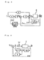
- FIG. 2 is a schematic diagram of a positioning mechanism.
- a positioning mechanism E has a load 2 on the top of a beam for exciting resonance vibration on a ball screw driving table 1 and the positioning mechanism E simulates a mechanical resonant system experienced in a semiconductor tester and the like.
- a servo motor 3 is operated by a servo amplifier 4, and a pulse signal of an encoder 5 mounted in the servo motor 3 is captured into the servo amplifier 4 through serial transmission and then is transmitted in parallel to a DSP (digital signal processor) 6 acting as a controller.
- a motor torque reference calculated by the DSP 6 is output to the servo amplifier 4, and motor driving current is controlled through a current control system and various filters in the servo amplifier 4. Since a torque reference is output and the sensor signal is captured through the servo amplifier 4, the positioning mechanism E including the servo amplifier 4 is controlled by the DSP 6.
- FIG. 3 is a block diagram showing a friction compensation control system realized in the DSP 6.
- a friction compensation control system is a two-degrees-of-freedom control system with a disturbance observer.
- r is a load position command
- ⁇ M is a motor position
- ⁇ L is a load position
- ⁇ M is a motor torque reference serving as a control input
- ⁇ adist is an estimated disturbance
- ⁇ Mo is a motor position target trajectory.
- N and D are feedforward compensators based on a coprime factorization description
- Z -8 is a dead time compensation element based on the Smith method
- C is a phase lead/lag compensator
- DOB is a disturbance observer acting as a state estimator.
- a nominal model used for designing the coprime factorized compensators N and D and the disturbance observer DOB is a two-inertia model PM2 expressed by the following equation (4) handling a primary vibration mode.
- Table 1 shows an example of each constant of the two-inertia model.
- FIG 4 is a block diagram of the disturbance observer DOB.
- ⁇ Mu is an input to an acceleration control system made up of the disturbance observer DOB
- ⁇ dist is a disturbance
- PM2 is the two-inertia model of the above equation (4)
- Z -8 is eight sample delay operator based on the Smith method
- Q is a filter for obtaining the proper characteristic of the disturbance observer DOB and determining a disturbance estimation speed.
- the disturbance observer DOB is configured using the filter Q which is made up of a low-pass filter and a notch filter and is expressed by the following equation (5) in consideration of robust stability in a high-frequency region.
- Table 2 shows an example of the parameter of the notch filter in the filter Q.
- initial value compensation is performed to the first-order low-pass filter of the filter Q expressed in the above equation (5).
- the first-order low-pass filter has an input uivc discretized by bilinear transform with a sampling period Ts and has the output ⁇ adist
- an output ⁇ adist[i] in a sample value system at time i can be expressed by the following equation (6) using present and past input and output.
- ⁇ ⁇ adist i 1 a 0 ⁇ b 0 ⁇ u i ⁇ c i + b 1 ⁇ u i ⁇ c ⁇ i - 1 - a 1 ⁇ ⁇ ⁇ adist ⁇ i - 1
- a 0 ⁇ Q ⁇ T s + 2
- a 1 ⁇ Q ⁇ T s - 2
- b 0 ⁇ Q ⁇ T s
- b 1 2 ⁇ ⁇ Q ⁇ T s
- the initial value compensation of the disturbance observer DOB in the present embodiment is nothing but the provision of an initial value compensation amount xivc for the above equation (6) at sample time i as expressed in the following equation (7).
- the following will focus on the present control system which is a motor trajectory tracking control system based on a coprime factorization description, and an initial value setting path is set as below:
- a dotted line indicates the initial value setting path of the disturbance observer DOB.
- the initial value setting path acts as transient output means and uses a rolling friction model RFM.
- variables ⁇ M, ⁇ M, and ⁇ 0 in the rolling friction model RFM according to equations (1) to (3) are calculated using an output waveform ⁇ MW of the compensator N.
- the initial value compensation amount xivc can be calculated without being affected by a dead time, sensor noise, and so on.
- the friction estimation value ⁇ adist obtained by the disturbance observer DOB at the just previous positioning/settling is used, so that a rolling friction force can be estimated in consideration of the initial value of a rolling friction force changing in a continuous motion.
- Figure 5 shows the behaviors of the rolling friction force during motions in the reverse direction and the same direction when the initial value Fr0 fluctuates. It is understood that the behaviors of the rolling friction force to be compensated vary according to the initial value Fr0 (points A to C) at the just previous positioning/settling and according to a subsequent motion direction (reverse direction: solid line, the same direction: dotted line). Thus it is expected that positioning response scatters in Bang-Bang compensation using a constant compensation torque which has been used in the prior art.
- the initial value compensation aims at improving the performance of friction compensation in a nonlinear spring region during startup, and thus the output value of the rolling friction model is adopted among eight samples during startup in which an effective friction force estimation value cannot be obtained.
- a method is used in which feedforward compensation is continuously performed on the model output value until the rolling friction model output reaches the Coulomb friction force in a rolling region, and after the rolling friction model output reaches the Coulomb friction force, the feedforward compensation is shifted to compensation control using a typical observer according to the time constant of the filter Q with the Coulomb friction force serving as an initial value.
- a following equation (8) is an arithmetic expression of the friction compensation initial value configured based on the initial value compensation algorithm of the disturbance observer DOB.
Landscapes
- Engineering & Computer Science (AREA)
- Physics & Mathematics (AREA)
- Automation & Control Theory (AREA)
- General Physics & Mathematics (AREA)
- Computer Vision & Pattern Recognition (AREA)
- Medical Informatics (AREA)
- Software Systems (AREA)
- Evolutionary Computation (AREA)
- Health & Medical Sciences (AREA)
- Artificial Intelligence (AREA)
- Control Of Position Or Direction (AREA)
- Feedback Control In General (AREA)
- Vehicle Body Suspensions (AREA)
- Paper (AREA)
- Automatic Control Of Machine Tools (AREA)
Claims (2)
- Steuerverfahren eines Positionierungsmechanismus (E), enthaltend die Schritte:Durchführen einer Kompensationsoptimalwertsteuerung einer Resonanzschwingung des Positionierungsmechanismus basierend auf einer Beschreibung einer teilerfremden Faktorzerlegung des Positionierungsmechanismus; undDurchführen einer Kompensationsrückkopplungssteuerung;
dadurch gekennzeichnet, dass die Kompensationsrückkopplungssteuerung einer Totzeit und einer nichtlinearen Reibung des Positionierungsmechanismus von einer Zustandsschätzvorrichtung (DOB) durchgeführt wird; und
dadurch, dass weiter die Schritte enthalten sindErzeugen einer Ausgabe der Zustandsschätzvorrichtung aus einem Reibungsabschätzungswert, der aus einem Modell für dynamische Eigenschaften von Rollreibung des Positionierungsmechanismus (E) erhalten wird, wodurch die Zustandsschätzvorrichtung (DOB) beginnt, den Positionierungsmechanismus (E) mit einer Abschätzungsverzögerung zu steuern. - Steuerung (6) eines Positionierungsmechanismus (E), enthaltend:einen Kompensator (N, D) zum Durchführen einer Kompensationsoptimalwertsteuerung einer Resonanzschwingung des Positionierungsmechanismus basierend auf einer Beschreibung einer teilerfremden Faktorzerlegung des Positionierungsmechanismus;gekennzeichnet durch eine Zustandsschätzvorrichtung (DOB) zum Durchführen einer Kompensationsrückkopplungssteuerung einer Totzeit und einer nichtlinearen Reibung des Positionierungsmechanismus; undtransiente Ausgabemittel zum Erzeugen einer Ausgabe der Zustandsschätzvorrichtung aus einem Reibungsabschätzungswert, der aus einem Modell für dynamische Eigenschaften von Rollreibung des Positionierungsmechanismus (E) erhalten wird, wodurch die Zustandsschätzvorrichtung (DOB) beginnt, den Positionierungsmechanismus (E) mit einer Abschätzungsverzögerung zu steuern.
Applications Claiming Priority (2)
| Application Number | Priority Date | Filing Date | Title |
|---|---|---|---|
| JP2006060825 | 2006-03-07 | ||
| PCT/JP2007/054250 WO2007105527A1 (ja) | 2006-03-07 | 2007-03-06 | 位置決め機構の制御方法および制御装置 |
Publications (3)
| Publication Number | Publication Date |
|---|---|
| EP1993007A1 EP1993007A1 (de) | 2008-11-19 |
| EP1993007A4 EP1993007A4 (de) | 2010-07-14 |
| EP1993007B1 true EP1993007B1 (de) | 2011-08-31 |
Family
ID=38509361
Family Applications (1)
| Application Number | Title | Priority Date | Filing Date |
|---|---|---|---|
| EP07715218A Not-in-force EP1993007B1 (de) | 2006-03-07 | 2007-03-06 | Steuerverfahren und steuerung eines positionierungsmechanismus |
Country Status (4)
| Country | Link |
|---|---|
| EP (1) | EP1993007B1 (de) |
| JP (1) | JP5028630B2 (de) |
| AT (1) | ATE522847T1 (de) |
| WO (1) | WO2007105527A1 (de) |
Families Citing this family (13)
| Publication number | Priority date | Publication date | Assignee | Title |
|---|---|---|---|---|
| JP4920612B2 (ja) * | 2008-02-07 | 2012-04-18 | 株式会社ハーモニック・ドライブ・システムズ | アクチュエータの角度伝達誤差補償方法 |
| WO2009110599A1 (ja) * | 2008-03-06 | 2009-09-11 | 国立大学法人横浜国立大学 | 制御装置、位置決め装置、制御方法、及び計測装置 |
| US8027112B2 (en) | 2009-10-30 | 2011-09-27 | Hitachi Asia Ltd. | Low frequency booster for RV/shock/friction disturbance rejection |
| JP2011227734A (ja) * | 2010-04-20 | 2011-11-10 | Tokai Rika Co Ltd | 入力装置 |
| JP5741711B2 (ja) * | 2011-12-13 | 2015-07-01 | トヨタ自動車株式会社 | 自動変速機の油圧制御装置 |
| JP5947732B2 (ja) * | 2013-02-25 | 2016-07-06 | 国立大学法人 東京大学 | 制御システム、外乱推定システム、制御方法、制御プログラム及び設計方法 |
| JP6214948B2 (ja) * | 2013-07-12 | 2017-10-18 | 三菱重工業株式会社 | 摩擦補償装置及び摩擦補償方法並びにサーボ制御装置 |
| JP6966062B2 (ja) * | 2017-01-31 | 2021-11-10 | 国立大学法人 名古屋工業大学 | 周波数応答解析アルゴリズム |
| JP7068870B2 (ja) * | 2018-03-09 | 2022-05-17 | 三菱重工業株式会社 | 制御装置、制御方法及びプログラム |
| CN110794678B (zh) * | 2019-11-05 | 2021-07-30 | 燕山大学 | 一种磁滞非线性受限下的四通道遥操作力反馈控制方法 |
| CN110989353B (zh) * | 2019-12-17 | 2021-01-19 | 华南理工大学 | 一种周期扰动观测器的设计方法 |
| JP7834300B2 (ja) * | 2022-08-31 | 2026-03-24 | 株式会社豊田自動織機 | 周波数応答関数同定システム |
| CN121290746B (zh) * | 2025-12-12 | 2026-03-17 | 长沙建益新材料有限公司 | 尾矿防渗用再生聚乙烯的多次循环利用工艺控制方法 |
Family Cites Families (5)
| Publication number | Priority date | Publication date | Assignee | Title |
|---|---|---|---|---|
| JPH09282008A (ja) * | 1996-04-15 | 1997-10-31 | Fuji Xerox Co Ltd | サーボ制御装置 |
| JP3532728B2 (ja) * | 1997-04-01 | 2004-05-31 | 株式会社リコー | 位置決め制御装置 |
| JP3621278B2 (ja) * | 1998-12-10 | 2005-02-16 | 三菱電機株式会社 | サーボ制御装置 |
| JP2003076425A (ja) * | 2001-09-05 | 2003-03-14 | Yamazaki Mazak Corp | 送り駆動系の制御装置 |
| JP3943061B2 (ja) * | 2003-08-22 | 2007-07-11 | 三菱電機株式会社 | サーボ制御装置 |
-
2007
- 2007-03-06 JP JP2008505064A patent/JP5028630B2/ja active Active
- 2007-03-06 EP EP07715218A patent/EP1993007B1/de not_active Not-in-force
- 2007-03-06 WO PCT/JP2007/054250 patent/WO2007105527A1/ja not_active Ceased
- 2007-03-06 AT AT07715218T patent/ATE522847T1/de not_active IP Right Cessation
Also Published As
| Publication number | Publication date |
|---|---|
| JPWO2007105527A1 (ja) | 2009-07-30 |
| EP1993007A1 (de) | 2008-11-19 |
| WO2007105527A1 (ja) | 2007-09-20 |
| JP5028630B2 (ja) | 2012-09-19 |
| ATE522847T1 (de) | 2011-09-15 |
| EP1993007A4 (de) | 2010-07-14 |
Similar Documents
| Publication | Publication Date | Title |
|---|---|---|
| EP1993007B1 (de) | Steuerverfahren und steuerung eines positionierungsmechanismus | |
| Maeda et al. | Initial friction compensation using rheology-based rolling friction model in fast and precise positioning | |
| JP4665096B2 (ja) | スライディングモード制御器を有する工作機械に用いられるモーションコントローラ | |
| Lee et al. | Friction compensation controller for load varying machine tool feed drive | |
| US20130238101A1 (en) | Load inertia estimation method and control parameter adjustment method | |
| CN102577096B (zh) | 伺服控制装置 | |
| US10591876B2 (en) | Method and system for adaptive compensation of dry friction | |
| JP2004213472A (ja) | 制御装置 | |
| JP2015018496A (ja) | 摩擦補償装置及び摩擦補償方法並びにサーボ制御装置 | |
| DE102018210864B3 (de) | Verfahren und System zum Regeln eines Roboters | |
| Sato et al. | Practical control of precision positioning mechanism with friction | |
| JP5574228B2 (ja) | 波動歯車減速機の温度変化に伴う摩擦特性変動を考慮したアクチュエータの適応型摩擦補償法 | |
| US9853585B2 (en) | Motor control apparatus, motor control method and motor control program | |
| JP2006227793A5 (de) | ||
| JP3943061B2 (ja) | サーボ制御装置 | |
| Bucci et al. | Nonlinear control algorithm for improving settling time in systems with friction | |
| JP4183057B2 (ja) | 数値制御システム | |
| Salisbury et al. | Closed-loop control of a complementary clamp piezoworm actuator | |
| Sankeshwari et al. | Performance analysis of disturbance estimation techniques for robust position control of DC motor | |
| Cai et al. | Fourier series based learning control and application to positioning table | |
| JP7743009B2 (ja) | 工作機械および工作機械用制御装置 | |
| Zhong et al. | Gain-scheduling robust control with guaranteed stability for ball screw drives with uncertain load mass and varying resonant modes | |
| JP4078396B2 (ja) | 位置決め制御装置 | |
| US20250144759A1 (en) | Machine tool, machine tool control system, and machine tool control method | |
| Iwasaki et al. | 2DOF control-based fast and precise positioning using disturbance observer |
Legal Events
| Date | Code | Title | Description |
|---|---|---|---|
| PUAI | Public reference made under article 153(3) epc to a published international application that has entered the european phase |
Free format text: ORIGINAL CODE: 0009012 |
|
| 17P | Request for examination filed |
Effective date: 20080903 |
|
| AK | Designated contracting states |
Kind code of ref document: A1 Designated state(s): AT BE BG CH CY CZ DE DK EE ES FI FR GB GR HU IE IS IT LI LT LU LV MC MT NL PL PT RO SE SI SK TR |
|
| RIN1 | Information on inventor provided before grant (corrected) |
Inventor name: MAEDA, YOSHIHIRO Inventor name: KAWAHUKU, MOTOHIRO Inventor name: IWASAKI, MAKOTO Inventor name: HIRAI, HIROMU |
|
| A4 | Supplementary search report drawn up and despatched |
Effective date: 20100615 |
|
| GRAP | Despatch of communication of intention to grant a patent |
Free format text: ORIGINAL CODE: EPIDOSNIGR1 |
|
| RIC1 | Information provided on ipc code assigned before grant |
Ipc: G05B 13/02 20060101AFI20110401BHEP |
|
| DAX | Request for extension of the european patent (deleted) | ||
| GRAS | Grant fee paid |
Free format text: ORIGINAL CODE: EPIDOSNIGR3 |
|
| GRAA | (expected) grant |
Free format text: ORIGINAL CODE: 0009210 |
|
| AK | Designated contracting states |
Kind code of ref document: B1 Designated state(s): AT BE BG CH CY CZ DE DK EE ES FI FR GB GR HU IE IS IT LI LT LU LV MC MT NL PL PT RO SE SI SK TR |
|
| REG | Reference to a national code |
Ref country code: CH Ref legal event code: EP Ref country code: GB Ref legal event code: FG4D |
|
| REG | Reference to a national code |
Ref country code: IE Ref legal event code: FG4D |
|
| REG | Reference to a national code |
Ref country code: DE Ref legal event code: R096 Ref document number: 602007016767 Country of ref document: DE Effective date: 20111124 |
|
| REG | Reference to a national code |
Ref country code: NL Ref legal event code: VDEP Effective date: 20110831 |
|
| LTIE | Lt: invalidation of european patent or patent extension |
Effective date: 20110831 |
|
| PG25 | Lapsed in a contracting state [announced via postgrant information from national office to epo] |
Ref country code: NL Free format text: LAPSE BECAUSE OF FAILURE TO SUBMIT A TRANSLATION OF THE DESCRIPTION OR TO PAY THE FEE WITHIN THE PRESCRIBED TIME-LIMIT Effective date: 20110831 Ref country code: SE Free format text: LAPSE BECAUSE OF FAILURE TO SUBMIT A TRANSLATION OF THE DESCRIPTION OR TO PAY THE FEE WITHIN THE PRESCRIBED TIME-LIMIT Effective date: 20110831 Ref country code: LT Free format text: LAPSE BECAUSE OF FAILURE TO SUBMIT A TRANSLATION OF THE DESCRIPTION OR TO PAY THE FEE WITHIN THE PRESCRIBED TIME-LIMIT Effective date: 20110831 Ref country code: IS Free format text: LAPSE BECAUSE OF FAILURE TO SUBMIT A TRANSLATION OF THE DESCRIPTION OR TO PAY THE FEE WITHIN THE PRESCRIBED TIME-LIMIT Effective date: 20111231 Ref country code: FI Free format text: LAPSE BECAUSE OF FAILURE TO SUBMIT A TRANSLATION OF THE DESCRIPTION OR TO PAY THE FEE WITHIN THE PRESCRIBED TIME-LIMIT Effective date: 20110831 |
|
| REG | Reference to a national code |
Ref country code: AT Ref legal event code: MK05 Ref document number: 522847 Country of ref document: AT Kind code of ref document: T Effective date: 20110831 |
|
| PG25 | Lapsed in a contracting state [announced via postgrant information from national office to epo] |
Ref country code: AT Free format text: LAPSE BECAUSE OF FAILURE TO SUBMIT A TRANSLATION OF THE DESCRIPTION OR TO PAY THE FEE WITHIN THE PRESCRIBED TIME-LIMIT Effective date: 20110831 Ref country code: SI Free format text: LAPSE BECAUSE OF FAILURE TO SUBMIT A TRANSLATION OF THE DESCRIPTION OR TO PAY THE FEE WITHIN THE PRESCRIBED TIME-LIMIT Effective date: 20110831 Ref country code: GR Free format text: LAPSE BECAUSE OF FAILURE TO SUBMIT A TRANSLATION OF THE DESCRIPTION OR TO PAY THE FEE WITHIN THE PRESCRIBED TIME-LIMIT Effective date: 20111201 Ref country code: CY Free format text: LAPSE BECAUSE OF FAILURE TO SUBMIT A TRANSLATION OF THE DESCRIPTION OR TO PAY THE FEE WITHIN THE PRESCRIBED TIME-LIMIT Effective date: 20110831 Ref country code: LV Free format text: LAPSE BECAUSE OF FAILURE TO SUBMIT A TRANSLATION OF THE DESCRIPTION OR TO PAY THE FEE WITHIN THE PRESCRIBED TIME-LIMIT Effective date: 20110831 |
|
| PG25 | Lapsed in a contracting state [announced via postgrant information from national office to epo] |
Ref country code: BE Free format text: LAPSE BECAUSE OF FAILURE TO SUBMIT A TRANSLATION OF THE DESCRIPTION OR TO PAY THE FEE WITHIN THE PRESCRIBED TIME-LIMIT Effective date: 20110831 |
|
| PG25 | Lapsed in a contracting state [announced via postgrant information from national office to epo] |
Ref country code: SK Free format text: LAPSE BECAUSE OF FAILURE TO SUBMIT A TRANSLATION OF THE DESCRIPTION OR TO PAY THE FEE WITHIN THE PRESCRIBED TIME-LIMIT Effective date: 20110831 Ref country code: CZ Free format text: LAPSE BECAUSE OF FAILURE TO SUBMIT A TRANSLATION OF THE DESCRIPTION OR TO PAY THE FEE WITHIN THE PRESCRIBED TIME-LIMIT Effective date: 20110831 |
|
| PG25 | Lapsed in a contracting state [announced via postgrant information from national office to epo] |
Ref country code: EE Free format text: LAPSE BECAUSE OF FAILURE TO SUBMIT A TRANSLATION OF THE DESCRIPTION OR TO PAY THE FEE WITHIN THE PRESCRIBED TIME-LIMIT Effective date: 20110831 Ref country code: PT Free format text: LAPSE BECAUSE OF FAILURE TO SUBMIT A TRANSLATION OF THE DESCRIPTION OR TO PAY THE FEE WITHIN THE PRESCRIBED TIME-LIMIT Effective date: 20120102 Ref country code: PL Free format text: LAPSE BECAUSE OF FAILURE TO SUBMIT A TRANSLATION OF THE DESCRIPTION OR TO PAY THE FEE WITHIN THE PRESCRIBED TIME-LIMIT Effective date: 20110831 Ref country code: RO Free format text: LAPSE BECAUSE OF FAILURE TO SUBMIT A TRANSLATION OF THE DESCRIPTION OR TO PAY THE FEE WITHIN THE PRESCRIBED TIME-LIMIT Effective date: 20110831 Ref country code: IT Free format text: LAPSE BECAUSE OF FAILURE TO SUBMIT A TRANSLATION OF THE DESCRIPTION OR TO PAY THE FEE WITHIN THE PRESCRIBED TIME-LIMIT Effective date: 20110831 |
|
| PG25 | Lapsed in a contracting state [announced via postgrant information from national office to epo] |
Ref country code: DK Free format text: LAPSE BECAUSE OF FAILURE TO SUBMIT A TRANSLATION OF THE DESCRIPTION OR TO PAY THE FEE WITHIN THE PRESCRIBED TIME-LIMIT Effective date: 20110831 |
|
| PLBE | No opposition filed within time limit |
Free format text: ORIGINAL CODE: 0009261 |
|
| STAA | Information on the status of an ep patent application or granted ep patent |
Free format text: STATUS: NO OPPOSITION FILED WITHIN TIME LIMIT |
|
| 26N | No opposition filed |
Effective date: 20120601 |
|
| REG | Reference to a national code |
Ref country code: DE Ref legal event code: R097 Ref document number: 602007016767 Country of ref document: DE Effective date: 20120601 |
|
| PG25 | Lapsed in a contracting state [announced via postgrant information from national office to epo] |
Ref country code: MC Free format text: LAPSE BECAUSE OF NON-PAYMENT OF DUE FEES Effective date: 20120331 |
|
| REG | Reference to a national code |
Ref country code: CH Ref legal event code: PL |
|
| GBPC | Gb: european patent ceased through non-payment of renewal fee |
Effective date: 20120306 |
|
| REG | Reference to a national code |
Ref country code: FR Ref legal event code: ST Effective date: 20121130 |
|
| REG | Reference to a national code |
Ref country code: IE Ref legal event code: MM4A |
|
| PG25 | Lapsed in a contracting state [announced via postgrant information from national office to epo] |
Ref country code: LI Free format text: LAPSE BECAUSE OF NON-PAYMENT OF DUE FEES Effective date: 20120331 Ref country code: GB Free format text: LAPSE BECAUSE OF NON-PAYMENT OF DUE FEES Effective date: 20120306 Ref country code: IE Free format text: LAPSE BECAUSE OF NON-PAYMENT OF DUE FEES Effective date: 20120306 Ref country code: CH Free format text: LAPSE BECAUSE OF NON-PAYMENT OF DUE FEES Effective date: 20120331 Ref country code: FR Free format text: LAPSE BECAUSE OF NON-PAYMENT OF DUE FEES Effective date: 20120402 |
|
| PG25 | Lapsed in a contracting state [announced via postgrant information from national office to epo] |
Ref country code: ES Free format text: LAPSE BECAUSE OF FAILURE TO SUBMIT A TRANSLATION OF THE DESCRIPTION OR TO PAY THE FEE WITHIN THE PRESCRIBED TIME-LIMIT Effective date: 20111211 |
|
| PGFP | Annual fee paid to national office [announced via postgrant information from national office to epo] |
Ref country code: DE Payment date: 20130326 Year of fee payment: 7 |
|
| PG25 | Lapsed in a contracting state [announced via postgrant information from national office to epo] |
Ref country code: BG Free format text: LAPSE BECAUSE OF FAILURE TO SUBMIT A TRANSLATION OF THE DESCRIPTION OR TO PAY THE FEE WITHIN THE PRESCRIBED TIME-LIMIT Effective date: 20111130 |
|
| PG25 | Lapsed in a contracting state [announced via postgrant information from national office to epo] |
Ref country code: MT Free format text: LAPSE BECAUSE OF FAILURE TO SUBMIT A TRANSLATION OF THE DESCRIPTION OR TO PAY THE FEE WITHIN THE PRESCRIBED TIME-LIMIT Effective date: 20110831 |
|
| PG25 | Lapsed in a contracting state [announced via postgrant information from national office to epo] |
Ref country code: TR Free format text: LAPSE BECAUSE OF FAILURE TO SUBMIT A TRANSLATION OF THE DESCRIPTION OR TO PAY THE FEE WITHIN THE PRESCRIBED TIME-LIMIT Effective date: 20110831 |
|
| PG25 | Lapsed in a contracting state [announced via postgrant information from national office to epo] |
Ref country code: LU Free format text: LAPSE BECAUSE OF NON-PAYMENT OF DUE FEES Effective date: 20120306 |
|
| PG25 | Lapsed in a contracting state [announced via postgrant information from national office to epo] |
Ref country code: HU Free format text: LAPSE BECAUSE OF FAILURE TO SUBMIT A TRANSLATION OF THE DESCRIPTION OR TO PAY THE FEE WITHIN THE PRESCRIBED TIME-LIMIT Effective date: 20070306 |
|
| REG | Reference to a national code |
Ref country code: DE Ref legal event code: R119 Ref document number: 602007016767 Country of ref document: DE |
|
| REG | Reference to a national code |
Ref country code: DE Ref legal event code: R119 Ref document number: 602007016767 Country of ref document: DE Effective date: 20141001 |
|
| PG25 | Lapsed in a contracting state [announced via postgrant information from national office to epo] |
Ref country code: DE Free format text: LAPSE BECAUSE OF NON-PAYMENT OF DUE FEES Effective date: 20141001 |