EP1993013A2 - Numerisches Kontrollverfahren für fünfachsige Verarbeitungsmaschinen - Google Patents
Numerisches Kontrollverfahren für fünfachsige Verarbeitungsmaschinen Download PDFInfo
- Publication number
- EP1993013A2 EP1993013A2 EP08154972A EP08154972A EP1993013A2 EP 1993013 A2 EP1993013 A2 EP 1993013A2 EP 08154972 A EP08154972 A EP 08154972A EP 08154972 A EP08154972 A EP 08154972A EP 1993013 A2 EP1993013 A2 EP 1993013A2
- Authority
- EP
- European Patent Office
- Prior art keywords
- point
- tool
- cutting
- vector
- block
- Prior art date
- Legal status (The legal status is an assumption and is not a legal conclusion. Google has not performed a legal analysis and makes no representation as to the accuracy of the status listed.)
- Granted
Links
Images


Classifications
-
- G—PHYSICS
- G05—CONTROLLING; REGULATING
- G05B—CONTROL OR REGULATING SYSTEMS IN GENERAL; FUNCTIONAL ELEMENTS OF SUCH SYSTEMS; MONITORING OR TESTING ARRANGEMENTS FOR SUCH SYSTEMS OR ELEMENTS
- G05B19/00—Program-control systems
- G05B19/02—Program-control systems electric
- G05B19/18—Numerical control [NC], i.e. automatically operating machines, in particular machine tools, e.g. in a manufacturing environment, so as to execute positioning, movement or co-ordinated operations by means of program data in numerical form
- G05B19/41—Numerical control [NC], i.e. automatically operating machines, in particular machine tools, e.g. in a manufacturing environment, so as to execute positioning, movement or co-ordinated operations by means of program data in numerical form characterised by interpolation, e.g. the computation of intermediate points between programmed end points to define the path to be followed and the rate of travel along that path
- G05B19/4103—Digital interpolation
-
- G—PHYSICS
- G05—CONTROLLING; REGULATING
- G05B—CONTROL OR REGULATING SYSTEMS IN GENERAL; FUNCTIONAL ELEMENTS OF SUCH SYSTEMS; MONITORING OR TESTING ARRANGEMENTS FOR SUCH SYSTEMS OR ELEMENTS
- G05B19/00—Program-control systems
- G05B19/02—Program-control systems electric
- G05B19/18—Numerical control [NC], i.e. automatically operating machines, in particular machine tools, e.g. in a manufacturing environment, so as to execute positioning, movement or co-ordinated operations by means of program data in numerical form
- G05B19/404—Numerical control [NC], i.e. automatically operating machines, in particular machine tools, e.g. in a manufacturing environment, so as to execute positioning, movement or co-ordinated operations by means of program data in numerical form characterised by control arrangements for compensation, e.g. for backlash, overshoot, tool offset, tool wear, temperature, machine construction errors, load, inertia
-
- G—PHYSICS
- G05—CONTROLLING; REGULATING
- G05B—CONTROL OR REGULATING SYSTEMS IN GENERAL; FUNCTIONAL ELEMENTS OF SUCH SYSTEMS; MONITORING OR TESTING ARRANGEMENTS FOR SUCH SYSTEMS OR ELEMENTS
- G05B2219/00—Program-control systems
- G05B2219/30—Nc systems
- G05B2219/35—Nc in input of data, input till input file format
- G05B2219/35158—Calculation of contact point of tool on surface, curve
-
- G—PHYSICS
- G05—CONTROLLING; REGULATING
- G05B—CONTROL OR REGULATING SYSTEMS IN GENERAL; FUNCTIONAL ELEMENTS OF SUCH SYSTEMS; MONITORING OR TESTING ARRANGEMENTS FOR SUCH SYSTEMS OR ELEMENTS
- G05B2219/00—Program-control systems
- G05B2219/30—Nc systems
- G05B2219/49—Nc machine tool, till multiple
- G05B2219/49344—Surface, 5-axis surface machining
-
- G—PHYSICS
- G05—CONTROLLING; REGULATING
- G05B—CONTROL OR REGULATING SYSTEMS IN GENERAL; FUNCTIONAL ELEMENTS OF SUCH SYSTEMS; MONITORING OR TESTING ARRANGEMENTS FOR SUCH SYSTEMS OR ELEMENTS
- G05B2219/00—Program-control systems
- G05B2219/30—Nc systems
- G05B2219/50—Machine tool, machine tool null till machine tool work handling
- G05B2219/50297—Compensation of positioning error due to a-axis, b-axis tool rotation
-
- G—PHYSICS
- G05—CONTROLLING; REGULATING
- G05B—CONTROL OR REGULATING SYSTEMS IN GENERAL; FUNCTIONAL ELEMENTS OF SUCH SYSTEMS; MONITORING OR TESTING ARRANGEMENTS FOR SUCH SYSTEMS OR ELEMENTS
- G05B2219/00—Program-control systems
- G05B2219/30—Nc systems
- G05B2219/50—Machine tool, machine tool null till machine tool work handling
- G05B2219/50336—Tool, probe offset for curves, surfaces, contouring
Definitions
- the present invention relates to a numerical control method for controlling a five-axis processing machine having two rotational axes and three linear axes, and also relates to operational control in the proximity of singular points where there is a possibility of the occurrence of unstable movement.
- a five-axis processing machine which carries out processing by moving a tool relatively in three linear axis directions with respect to a workpiece (processing object), as well as inclining the tool relatively with respect to the workpiece about two rotational axes.
- a processing method using a five-axis processing machine which processes a curved surface by performing curve interpolation, on the basis of command point sequence data created by a CAD/CAM apparatus or an associated apparatus, and a command vector sequence which instructs the angles of inclination of the workpiece and the tool, wherein smooth processed surfaces are obtained by interpolation of a smooth curve which is approximate to a prescribed curve (see Japanese Patent Application Laid-Open No. 2005-182437 ).
- a joint interpolation range is determined on the basis of the attitude at two time points, in such a manner that the error in the attitude of the tool between the two time points assigned to the tool is equal to or less than a tolerable value, and the attitude of the tool is controlled within this joint interpolation range by means of joint interpolation (namely, interpolation for determining the values of the joint coordinates of the respective axes, on the basis of the positional vector and the attitude vector at the two points) (see Japanese Patent Application Laid-Open No. 2004-220435 ).
- joint interpolation namely, interpolation for determining the values of the joint coordinates of the respective axes, on the basis of the positional vector and the attitude vector at the two points
- a cutting point which is where a workpiece is actually processed by a tool, differs from a control point, which is the position to which the tool is controlled with respect to the workpiece.
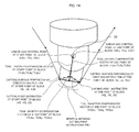
- Fig. 1 is a diagram showing the relationship between a cutting point which is indicated when using a ball end mill as a tool 1, and the controlled tool position, in a five-axis processing machine having three linear axes, X, Y, Z, and two rotational axes, axis A which rotates about the X axis, and axis C which rotates about the Z axis.
- a cutting point is instructed in the form of a position (X, Y, Z) of the X, Y, Z axes in the perpendicular coordinates system corresponding to the linear axes X, Y, Z.
- the control point for controlling the position of the tool 1 with respect to the workpiece in response to this cutting point instruction (X, Y, Z) is not the point where the tip of the tool 1 makes contact with the workpiece (cutting point instruction point), but rather a linear axis position (Xc, Yc, Zc) which is separated from this cutting point instruction point, and therefore the instructed cutting point position (X, Y, Z) does not coincide with the linear axis position (Xc, Yc, Zc) corresponding to same.
- the linear axis position (Xc, Yc, Zc) is determined by applying tool diameter compensation and tool length compensation, and this linear axis position (Xc, Yc, Zc) and the rotational axis positions (A, C) are controlled accordingly.
- the tool diameter compensation is determined on the basis of a cutting surface perpendicular direction instruction (I, J, K) which is instructed together with the cutting point position (X, Y, Z), and an established tool diameter compensation amount TR.
- the tool length compensation is determined on the basis of the tool direction which is specified by the instructions supplied to the respective rotational axes, the A axis and the C axis, the established tool diameter compensation amount TR, and the tool length compensation amount TL.
- the instructed cutting point position (X, Y, Z) does not coincide with the position of the tool 1 with respect to the workpiece, in other words, with the position (Xc, Yc, Zc) of the controlled linear axes.
- a square end mill which has a square-shaped cross-section when rotated about the main shaft, or a radius end mill which has a curved radius applied to the corners of the tool, is used instead of a ball end mill, and here also, the instructed cutting point position does not coincide with the controlled linear axis position.
- the interval between the instructed cutting points should be similar to the movement of the control point. In other words, it is desirable that if the interval between the instructed cutting points is small, then the corresponding movement of the control point is also small, and if the interval between the instructed cutting points is large, then the corresponding movement of the control point is also large.
- the general relationship between an instructed cutting point and a control point is as shown in Fig. 2 .
- the interval between the instructed cutting points may differ greatly from the movement of the control point.
- Fig. 3 is an illustrative operational diagram of a case where a ball end mill is used as a tool 1 and is controlled by determining the positions of three linear axes X, Y, Z, and two rotational axes, A and C, by means of cutting point instructions.
- a program such as that shown in Fig. 4 is used as the processing program.
- Fig. 4 illustrates the processing program on the left-hand side of the drawing, accompanied by an explanation of the processing program, on the right-hand side.
- "G43.8” indicates a cutting point instruction code
- "H01” indicates that the tool length compensation number is “01” (in other words, that the tool length compensation amount indicated by this tool length compensation number is to be used)
- "D01” indicates that the tool diameter compensation number is "01” (in other words, that the tool diameter compensation amount indicated by this tool diameter compensation number is to be used).
- X_Y_Z_A_C_I_J_K_ is a block of cutting point instructions
- X_Y_Z_ is a cutting point instruction which indicates the position of a cutting point in terms of the X, Y, Z axes of a perpendicular coordinates system
- A_C_ is a tool direction instruction
- I_J_K_ is an instruction which specifies the direction perpendicular to the cutting surface, at the cutting point.
- G49 is an instruction which cancels and terminates the processing control based on that cutting point instruction.
- the tool diameter compensation amount TR, the tool length compensation amount TL, and the corner radius compensation amount CR which is described hereinafter, are set as parameters for each respective compensation number.
- Fig. 5 shows an example of the tool compensation amount settings. If the corner radius compensation amount CR is set to "0.0", then this indicates that there is no corner radius, and means that the tool is a square end mill. Furthermore, if the tool diameter compensation amount TR is set to the same numerical figure as the corner radius compensation amount CR, then this means that the tool is a ball end mill. In the example shown in Fig. 5 , the compensation number "01" indicates a ball end mill, the compensation number "02" indicates a radius end mill, and the compensation number "03" indicates a square end mill.
- the controller reads in the instructions of one block (X, Y, Z, A, C, I, J, K), from the processing program.
- the block cutting point instruction (X, Y, Z) thus read in is taken as the cutting point instruction (XE, YE, ZE) at the end point of the current block, and the block cutting point instruction (X, Y, Z) read in respect of the immediately previous block is taken as the cutting point instruction (XS, YS, ZS) at the start point of the current block.
- the cutting surface perpendicular direction instruction (I, J, K) read in from the processing program is taken as the cutting surface perpendicular direction instruction (IE, JE, KE) at the end point of the current block
- the cutting surface perpendicular direction instruction (I, J, K) read in the immediately previous block is taken as the cutting surface perpendicular direction instruction (IS, JS, KS) at the start point of the current block.
- the linear axis control point position (Xc, Yc, Zc) and the rotational axis control point positions (Ac, Cc) are determined for each interpolation cycle, and processing is carried out by driving and controlling the servo motors which drive the respective axes in order that they are moved to these positions.
- Fig. 6 is an illustrative diagram of processing for determining a linear axis control position and rotational axis control positions according to the cutting point instruction, for each interpolation cycle, in a case where the tool 1 used is a square end mill.
- the processing program is the same as the processing program shown in Fig. 4 , and a tool length compensation number ("H03") and a tool diameter compensation number ("D03") are instructed.
- the compensation number "03" is selected from the tool compensation amount settings examples shown in Fig. 5 , and since the corner radius compensation amount CR is set to "0.0", then a square end mill is designated.
- the linear axis control point position (Xc, Yc, Zc) and the rotational axis control point positions (Ac, Cc) are determined at each interpolation cycle, and processing is carried out by controlling and driving the servo motors which drive the respective axes, in such a manner that the axes are moved to these positions.
- Fig. 7 is an illustrative diagram of processing for determining the linear axis control point position and the rotational axis control point positions, for each respective interpolation cycle, on the basis of a cutting point instruction, in a case where the tool 1 is a radius end mill.
- Fig. 8 shows an example of the processing program used in this case. This processing program is the same as that shown in Fig. 4 , but in this case, the tool length compensation number "H02" and the tool diameter compensation number "D02" are indicated, and hence the compensation number 02 is selected from the tool compensation amount settings example shown in Fig. 5 , and since the corner radius compensation amount CR is "2.0", then a radius end mill is specified. Apart from this, the procedure is the same as the example shown in Fig. 4 .
- processing is carried out by driving and controlling the servo motors which drive the axes, in such a manner that the axes are moved to the linear axis control point position (Xc, Yc, Zc) and the rotational axis control point positions (Ac, Cc) determined at each respective interpolation cycle.
- Fig. 9 is an illustrative diagram of the proximity of singular points where control becomes unstable. This example relates to a case of instability in control occurring at a singular point where the interval between the cutting point instructions is small, but the movement distance of the control point is large (below, this singular point is called "singular point 1"). This singular point 1 occurs under conditions such as those described below.
- Fig. 10 is an illustrative movement diagram of this singular point 2. This singular point occurs under conditions such as the following.
- the directions of the tool direction vector (TSx, TSy, TSz) at the start point of a block and the tool direction vector (TEx, TEy, TEz) at the end point of the block are close together, the tool length compensation vector (TLx, TLy, TLz) at the start point of a block and the tool length compensation vector (TLx, TLy, TLz) at the end point of the block are mutually superimposed, and the position of the linear axis control point, which is determined by adding the tool diameter compensation vector and the tool length compensation vector to the cutting point instruction, performs a small loop-shaped movement.
- a milling tool which does not have a corner radius section is used, control points for the respective axes are determined at respective interpolation cycles, based on a tool diameter compensation amount and a tool length compensation amount which are set in advance, and also on cutting points, a cutting surface perpendicular direction and a tool direction which are instructed by a processing program, and in which the respective axes are driven and controlled to positions of the control points thus determined.
- This method further comprises step of determining, at each interpolation cycle, an interpolated cutting point position, an interpolated cutting surface perpendicular direction vector, an interpolated tool direction vector, a tool diameter compensation vector, and a tool length compensation vector, based on the tool diameter compensation amount and tool length compensation amount which are set in advance, and also on the cutting point, cutting surface perpendicular direction and tool direction which are instructed by a processing program; step of determining, in cases where an angle formed between the interpolated cutting surface perpendicular direction vector and the interpolated tool direction vector is smaller than a predetermined first set value, a linear axis control point by taking the tool diameter compensation vector for the current interpolation cycle as the tool diameter compensation vector calculated in the interpolation cycle immediately before the angle become smaller, and by adding this tool diameter compensation vector and the tool length compensation vector to the interpolated cutting point position; and step of determining, in cases where in the calculation of the tool diameter compensation vector in subsequent interpolation cycles the angle formed between the interpolated cutting surface perpendicular direction vector and
- a milling tool which has a corner radius section is used, control points for the respective axes are determined at respective interpolation cycles, based on a predetermined tool diameter compensation amount, a corner radius compensation amount and tool length compensation amount which are set in advance, and also on a processing program in which cutting points, a cutting surface perpendicular direction and a tool direction are instructed, and in which the respective axes are driven and controlled to positions of the control points thus determined.
- This method further comprises step of determining, at each interpolation cycle, an interpolated cutting point position, an interpolated cutting surface perpendicular direction vector, an interpolated tool direction vector, a tool diameter compensation vector, a corner radius compensation vector, and a tool length compensation vector, based on the tool diameter compensation amount, corner radius compensation amount and tool length compensation amount which are set in advance, and also on the cutting point, cutting surface perpendicular direction and tool direction which are instructed by a processing program; step of determining, in cases where an angle formed between the interpolated cutting surface perpendicular direction vector and the interpolated tool direction vector is smaller than a predetermined first set value, a linear axis control point by taking the tool diameter compensation vector for the current interpolation cycle as the tool diameter compensation vector calculated in the interpolation cycle immediately before the angle become smaller, and by adding this tool diameter compensation vector, and the corner radius compensation vector and the tool length compensation vector, to the interpolated cutting point position; and step of determining, in cases where the angle formed between the interpolated cutting surface perpen
- a milling tool which does not have a corner radius section or a ball end mill is used, linear axis control points and rotational axis control points are determined at respective interpolation cycles, based on a tool diameter compensation amount and a tool length compensation amount which are set in advance, and also on cutting points, a cutting surface perpendicular direction and a tool direction which are instructed by a processing program, and in which the respective axes are driven and controlled to positions of the respective control points thus determined.
- This method further comprises step of determining a cutting point position and a linear axis control point respectively at a start point and an end point for each of blocks thereof; and step of assuming that the linear axis control point at the end point of the current block is equal to the linear axis control point at the start point of the current block so that movement of the linear axis in accordance with the instructions in the current block does not occur, when judgment is made that a distance between the linear axis control points at the start point and the end point of the block is smaller than a predetermined second set value, and that a distance between the cutting point positions at the start point and the end point of the block is greater than a predetermined third set value, or when judgment is made that a ratio of the distance between the linear axis control points at the start point and the end point of the block to the distance between the cutting point positions at the start point and the end point of the block is less than a predetermined fourth set value.
- a fourth mode of the numerical control method for controlling a five-axis processing machine corresponds to the third mode of the numerical control method in which "assuming that the linear axis control point at the end point of the current block is equal to the linear axis control point at the start point of the current block so that movement of the linear axis in accordance with the instructions in the current block does not occur" in the third mode is replaced with "setting the instruction of the current block to a linear movement instruction".
- a milling tool which has a corner radius section is used, linear axis control points and rotational axis control points are determined at respective interpolation cycles, based on a predetermined tool diameter compensation amount, a corner radius compensation amount and a tool length compensation amount which are set in advance, and also on cutting points, a cutting surface perpendicular direction and a tool direction which are instructed by a processing program, and in which the respective axes are driven and controlled to positions of the respective control points thus determined.
- This method further comprises step of determining a cutting point position and a linear axis control point respectively at a start point and an end point for each of blocks thereof; and step of assuming that the linear axis control point at the end point of the current block is equal to the linear axis control point at the start point of the current block so that movement of the linear axis in accordance with the instructions in the current block does not occur, when judgment is made that a distance between the linear axis control points at the start point and the end point of the block is smaller than a predetermined second set value, and that a distance between the cutting point positions at the start point and the end point of the block is greater than a predetermined third set value, or when judgment is made that a ratio of the distance between the linear axis control points at the start point and the end point of the block to the distance between the cutting point positions at the start point and the end point of the block is less than a predetermined fourth set value.
- a sixth mode of the numerical control method for controlling a five-axis processing machine corresponds to the fifth mode of the numerical control method in which "assuming that the linear axis control point at the end point of the current block is equal to the linear axis control point at the start point of the current block so that movement of the linear axis in accordance with the instructions in the current block does not occur" in the fifth mode is replaced with "setting the instruction of the current block to a linear movement instruction".
- the present invention is able to prevent unstable operation arising at singular points where the interval between instructions in the cutting point instructions is small but the movement distance of the linear axis control point is large, in a five-axis processing machine having three linear axes and two rotational axes. Furthermore, it is also possible to prevent excessive cutting arising at a singular point where the interval between the positions of the cutting point instructions is large but the movement of the control point when processing between these points is small.
- Fig. 11 is a principal block diagram of a numerical controller for carrying out one embodiment of the numerical control method according to the present invention.
- the CPU 11 is a processor which executes overall control of the numerical controller 10.
- This processor 11 is connected respectively via a bus 20, to a memory 12, a display device 13, an input device 14 such as a keyboard, an interface 15, an axis control circuit 16 for each of the respective axes which drive and control the servo motors of the axes, a spindle control circuit 18 which drives and controls the spindle (main shaft), and the like.
- the memory 12 is constituted by a ROM, RAM, FRAM, or the like.
- the processor 11 reads out, via the bus 20, a system program stored in the memory 12 and controls the whole of the numerical controller in accordance with the system program thus read out.
- the memory 12 is stored with a processing program, such as a program constituted by cutting point instructions read in via the interface 15, various processing programs input via the display device 13 and the input device 14, and various data such as settings data, and the like.
- a processing program such as a program constituted by cutting point instructions read in via the interface 15, various processing programs input via the display device 13 and the input device 14, and various data such as settings data, and the like.
- the numerical controller shown in Fig. 11 differs from a conventional controller in that software for determining the vicinities of the singular point 1 and the singular point 2 described above and preventing unstable operation and excessive cutting is stored in the memory 12.
- the axis control circuit 16 of the respective axes receives a movement instruction amount for the respective axes from the processor 11, and position and speed feedback signals from position/speed detectors which are respectively built into the servo motors 22 of the respective axes, and it performs feedback control of the position and speed and outputs a command for the respective axes to the servo amplifier 17.
- the servo amplifier 17 drives the respective servo motors 22 of the respective axes (X axis, Y axis, Z axis, A axis, C axis) of the machine (control object).
- the feedback of the position and speed are omitted from the drawings.
- the spindle control circuit 18 receives a main shaft rotation instruction from the processor 11 and speed feedback from the speed detector which detects the rotational speed of the main shaft, and implements feedback control of the speed so as to output a spindle speed signal to the spindle amplifier 19.
- the spindle amplifier 19 receives the spindle speed signal and causes the spindle motor 23 to rotate at the instruction speed of rotation.
- the hardware composition of the numerical controller described above is the same as that of the prior art, the point of difference being that software for determining the singular point 1 and the singular point 2 described above and thereby preventing unstable operation and excessive cutting is stored additionally in the memory 12.
- Fig. 12 is a diagram describing a process for determining a singular point 1, and a process for avoiding unstable movement when the singular point 1 is determined.
- the angle ⁇ formed between these two vectors is found and it is judged whether or not this angle ⁇ is smaller than a previously set parameter value [Prm( ⁇ )). If the angle ⁇ is smaller than the set value [Prm( ⁇ )), then this means that the front end plane of the square end mill or the radius mill, and the processing plane are in a state close to parallel, and hence there is a high possibility of satisfying the conditions (a) to (c) under which the singular point 1 described above occurs, and there is a high possibility of being in the proximity of a singular point 1.
- the tool diameter compensation vector (TCx, TCy, TCz) is set to the tool diameter compensation vector (TCx, TCy, TCz) of the (immediately) previous interpolation cycle (hereinafter, the tool diameter compensation vector of the immediately previous interpolation cycle is represented as "TC0x, TC0y, TC0z"), and the respective axes are controlled by determining the linear axis control point position (Xc, Yc, Zc) and the rotational axis control point positions (Ac, Cc) accordingly.
- the tool diameter compensation vector (TCx, TCy, TCz) changes significantly, the linear axis control point position (Xc, Yc, Zc) varies, thereby making the movement unstable.
- the tool diameter compensation vector (TCx, TCy, TCz) is set to the tool diameter compensation vector (TC0x, TC0y, TC0z) of the (immediately) previous interpolation cycle so as not to change the tool diameter compensation vector (TCx, TCy, TCz).
- the singular point 1 is eliminated and instability of the movement is removed.
- the processing reverts to determining the position of the control point on the basis of the current tool diameter compensation vector (TCx, TCy, TCz), as usual.
- the processing reverts to normal processing in this way, it is possible to select one of two procedures: either to set the movement speed of the control point to the instruction speed (method 1), or to set the movement speed of the control point to the maximum speed (method 2).
- Fig. 13 is a flowchart of the processing carried out for each interpolation cycle, which shows an algorithm centered on processing for determining a singular point 1 and processing for preventing unstable operation in the proximity of the singular point in the first embodiment.
- the processor 11 of the numerical controller reads in a block of instructions (X, Y, Z, A, C, I, J, K) from the processing program, and carries out interpolation processing, as in the prior art, in order to obtain:
- step a1 determines (in step a1):
- step a2 it is judged whether or not the tool specified by the program is a ball end mill (step a2). If a ball end mill is designated, the phenomenon of the singular point 1 does not occur, and therefore the procedure proceeds to step a7, and similarly to the prior art, the linear axis control point position and the rotational axis control point positions are determined, the movement instructions to the respective axis positions thus determined are output to the respective axis control circuits 16, and the servo motors 22 of the respective axes are driven and controlled accordingly.
- step a2 if the designated tool is a square end mill or a radius end mill (rather than a ball end mill), then the procedure proceeds to step a3, and it is judged whether or not the value of the internal product of the interpolated cutting surface perpendicular direction vector (It, Jt, Kt) and the interpolated tool direction vector (Ttx, Tty, Ttz) is greater than the cosine of the value (Prm ( ⁇ )) set as a parameter, namely, cos(Prm( ⁇ )), thereby judging whether or not the angle ⁇ formed by the interpolated cutting surface perpendicular direction vector (It, Jt, Kt) and the interpolated tool direction vector (Ttx, Tty, Ttz) is smaller than the set value (Prm( ⁇ )).
- step a8 If it is judged that the angle ⁇ is not smaller than the set value (Prm( ⁇ )) (in other words, if it is judged that ⁇ ⁇ Prm( ⁇ )), then it is next judged whether or not the flag FA is set to "1" (step a8).
- the flag FA is set to "0" in an initial setting.
- the speed of the cutting point is set to the speed specified by the program (step a12).
- the tool diameter compensation vector (TCx, TCy, TCz) and the corner radius compensation vector (CCx, CCy, CCz) which are determined in Step a1 in the current processing cycle are stored in a register which stores the tool diameter compensation vector (TC0x, TC0y, TC0z) of the previous interpolation cycle (and also a register which stores the corner radius compensation vector (CC0x, CC0y, CC0z) of the previous interpolation cycle, in case where a radius end mill is designated).
- linear axis control point position and the rotational axis control point positions are determined.
- the linear axis control point position (Xc, Yc, Zc) is determined by adding the tool diameter compensation vector (TCx, TCy, TCz) and the tool length compensation vector (TLx, TLy, TLz) to the interpolated cutting point position (Xt, Yt, Zt), and furthermore, the rotational axis control point positions (Ac, Cc) are determined from the interpolated tool direction vector (Ttx, Tty, Ttz).
- the linear axis control point position (Xc, Yc, Zc) is determined by adding the corner radius compensation vector (CCx, CCy, CCz), the tool diameter compensation vector (TCx, TCy, TCz) and the tool length compensation vector (TLx, TLy, TLz) to the interpolated cutting point position (Xt, Yt, Zt), and furthermore, the rotational axis control point positions (Ac, Cc) are determined from the interpolated tool direction vector (Ttx, Tty, Ttz) (step a7).
- Movement instructions to the positions of the respective axes which have been determined in this way are output to the respective axis control circuits 16, and are used to drive and control the servo motors 22 of the respective axes.
- step a3 if it is judged that the angle ⁇ formed between the interpolated cutting surface perpendicular direction vector (It, Jt, Kt) and the interpolated tool direction vector (Ttx, Tty, Ttz) is smaller than the set value (Prm( ⁇ )) ( ⁇ ⁇ Prm( ⁇ )), then the flag FA is set to "1" (step a4), the tool diameter compensation vector (TC0x, TC0y, TC0z) of the previous interpolation cycle, which is stored in the register, is set as the tool diameter compensation vector (TCx, TCy, TCz) for the current interpolation cycle, and the corner radius compensation vector (CC0x, CC0y, CC0z) of the previous interpolation cycle is set as the corner radius compensation vector (CCx, CCy, CCz) for the current interpolation cycle (step a5).
- step a6 the processing in step a6 described above is executed, the tool diameter compensation vector (TCx, TCy, TCz) and the corner radius compensation vector (CCx, CCy, CCz) used in the current interpolation cycle are stored in the register, and hence become the "tool diameter compensation vector (TC0x, TC0y, TC0z) and the corner radius compensation vector (CC0x, CC0y, CC0z) of the previous interpolation cycle" in the case of the next interpolation cycle.
- step a5 the processing in step a7 described above is executed, and the linear axis control point position (Xc, Yc, Zc) and the rotational axis control point positions (Ac, Cc) are determined.
- the tool diameter compensation vector (TCx, TCy, TCz), and the corner radius compensation vector (CCx, CCy, CCz) are set respectively to the tool diameter compensation vector (TC0x, TC0y, TC0z) of the previous interpolation cycle and the corner radius compensation vector (CC0x, CC0y, CC0z) of the previous interpolation cycle, and therefore the linear axis control point position (Xc, Yc, Zc) and the rotational axis control point positions (Ac, Cc) are determined.
- the corner radius compensation vector (CCx, CCy, CCz) and the tool diameter compensation vector (TCx, TCy, TCz) are stabilized and the singular point 1 is eliminated, allowing an unstable movement to be prevented. It should be noted that great variation of the tool diameter compensation vector (TCx, TCy, TCz) will cause instability of the linear axis control point position (Xc, Yc, Zc) significantly, so it is important, in this case, to stabilize the tool diameter compensation vector (TCx, TCy, TCz).
- step a3 it is judged at step a3 that the angle ⁇ formed between the interpolated cutting surface perpendicular direction vector (It, Jt, Kt) and the interpolated tool direction vector (Ttx, Tty, Ttz) is smaller than the established value (Prm( ⁇ )) (namely, ⁇ ⁇ Prm( ⁇ )) (in other words, provided that the judgment is Yes), then the processing in steps a1 to a7 is carried out for each respective interpolation cycle, and the linear axis control point position (Xc, Yc, Zc) and the rotational axis control point positions (Ac, Cc) are determined in such a manner that the angle ⁇ formed between the interpolated cutting surface perpendicular direction vector (It, Jt, Kt) and the interpolated tool direction vector (Ttx, Tty, Ttz) is not smaller than the set value (Prm( ⁇ )), and the respective axes are controlled so as to move to these positions.
- step a3 if it is judged that the angle ⁇ formed between the interpolated cutting surface perpendicular direction vector (It, Jt, Kt) and the interpolated tool direction vector (Ttx, Tty, Ttz) is greater than the set value (Prm( ⁇ )) (in other words, it is judged that ⁇ > Prm( ⁇ )(in other words, provided that the judgment is No), then at the following step a8, if the flag FA is judged to be "1" (if it has been judged that the angle ⁇ is smaller than the set value (Prm( ⁇ )) until the previous interpolation cycle, but it has been judged that ⁇ ⁇ (Prm( ⁇ )) in the current interpolation cycle), then the flag FA is set to "0" (step a9), and thereafter, it is judged whether or not the set parameter (Prm(BF)) is set to "1" (step a10).
- the settings parameter (Prm(BF)) is the movement speed used for the cutting point, and it is set to the indicated speed or the maximum speed. If this set parameter (Prm(BF)) is set to "1", then the movement speed of the cutting point is set to the instructed speed (step a12). On the other hand, if the set parameter (Prm(BF)) is set to "0", then the movement speed of the cutting point is changed to a maximum speed within a range where none of the axes exceeds the maximum speed set by the parameter (step a11).
- the reason for changing the speed of the cutting point from the instruction speed to the maximum speed is because in an interpolation cycle where it has at first been considered that the tool is in the proximity of a singular point 1 and it is then judged that in actuality there is no singular point 1, there is a risk that the tool may move with a sudden speed, and therefore it is sought to prevent the tool from being moved with an excessive speed in this way.
- step a6 the speed of the cutting point is changed or maintained, and the procedure then proceeds to step a6.
- the respective data are determined by carrying out interpolation processing at the set speed, but if the speed of the cutting point has been changed to the maximum speed by the processing in step all of the preceding interpolation cycle, then interpolation processing is carried out at this maximum speed, and the respective data are determined accordingly.
- step a9 since the flag FA has been set to "0" at step a9, then the procedure proceeds from step a8 to step a12 and the speed is returned to the standard instructed speed.
- Fig. 14 is an illustrative diagram of processing for determining a singular point 2 and processing for avoiding movement which causes excessive cutting when a singular point 2 has been determined, as implemented in a second embodiment of a numerical control method according to the present invention.
- the second embodiment relates to an example where the tool used is a ball end mill.
- the tool length compensation vector (TLSx, TLSy, TLSz) at the start point of a block and the tool length compensation vector (TLEx, TLEy, TLEz) at the end point of the block are close together in the proximity of a singular point 2, then for the sake of convenience, they are represented by the same arrow and position.
- linear axis control point (XSc, YSc, ZSc) at the start point of a block and the linear axis control point (XEc, YEc, ZEc) at the end point of the block are close together in the proximity of a singular point 2, then for the sake of convenience, they are represented by the same arrow and the same position.
- Fig. 15 is a flowchart of processing which is implemented in block units, and which illustrates an algorithm centered on processing for determining a singular point 2 and processing for preventing unstable movement in the proximity of the singular point, according to the second embodiment.
- the linear axis control point position (XEc, YEc, ZEc) at the end point of a block is made identical to the linear axis control point position (XSc, YSc, ZSc) at the start point of the block, in such a manner that it is possible to select either to prevent the occurrence of movement of the linear axis control point, or to set a linear movement for the movement operation from the linear axis control point position (XSc, YSc, ZSc) at the start point of a block until the linear axis control point position (XEc, YEc, ZEc) at the end point of the block.
- a program command or signal instead of using an established parameter value to make the selection described above, it is also possible to use a program command or signal.
- the instruction block is read in and the cutting point instruction (XS, YS, ZS) and the cutting surface perpendicular direction instruction (IS, JS, KS) at the start point of the block thus read in is determined.
- the tool diameter compensation vector (TCSx, TCSy, TCSz) at the start point of the block is determined by multiplying the cutting surface perpendicular direction instruction (IS, JS, KS) at the start point of the block by the tool diameter compensation amount TR.
- the cutting surface perpendicular direction instruction (IS, JS, KS) is a unit vector.
- the tool direction vector (TSx, TSy, TSz) at the start point of a block is determined from the indicated tool direction instructions A, C at the start point of a block and the end point of the block.
- the tool length compensation vector (TLSx, TLSy, TLSz) at the start point of the block is determined by multiplying the compensation amount differential (tool length compensation amount TL - tool diameter compensation amount TR) by the tool direction vector (TSx, TSy, TSz) at the start point of the block thus determined.
- the tool diameter compensation vector (TCSx, TCSy, TCSz) at the start point of a block and the tool length compensation vector (TLSx, TLSy, TLSz) at the start point of the block are added to the cutting point instruction (XS, YS, ZS) at the start point of the block, thereby determining the linear axis control point (XSc, YSc, ZSc) at the start point of the block (step b1).
- the processing for determining the linear axis control point (XSc, YSc, ZSc) at the start point uses the same method for determining the linear axis control point (Xc, Yc, Zc) at an interpolation point, as described above, and further details thereof are omitted here.
- the cutting point instruction (XE, YE, ZE) and the cutting surface perpendicular direction instruction (IE, JE, KE) at the end point of the block are determined.
- the tool diameter compensation vector (TCEx, TCEy, TCEz) at the end point of the block is determined by multiplying the tool diameter compensation amount TR by the cutting surface perpendicular direction instruction (IE, JE, KE).
- the cutting surface perpendicular direction instruction (IE, JE, KE) is a unit vector.
- the tool direction vector (TEx, TEy, TEz) at the end point of the block is determined on the basis of the indicated tool direction instructions A, C for the start point of the block and the end point of the block.
- the tool length compensation vector (TLEx, TLEy, TLEz) at the end point of the block is determined by multiplying the compensation amount differential (tool length compensation amount TL - tool diameter compensation amount TR) by the tool direction vector (TEx, TEy, TEz) at the end point of the block.
- the linear axis control point (XEc, YEc, ZEc) at the end point of the block is determined by adding the tool diameter compensation vector (TCEx, TCEy, TCEz) at the end point of the block and the tool length compensation vector (TLEx, TLEy, TLEz) at the end point of the block to the cutting point instruction (XE, YE, ZE) at the end point of the block (step b2).
- the processing for determining the linear axis control point (XEc, YEc, ZEc) at the end point is the same as the processing for determining the linear axis control point (Xc, Yc, Zc) at an interpolation point as described above, and further explanation thereof is omitted here.
- the end point of one block is the start point of the next block, and therefore the data determined for the end point of a block can be used as the data for the start point of the next block. Consequently, in the next block, the processing in step b1 can replace the respective data for the end point of the block which was determined at step b2 in the previous cycle, with the data of the start point of the current block.
- the distance CD between the linear axis control point (XSc, YSc, ZSc) at the start point of a block and the linear axis control point (XEc, YEc, ZEc) at the end point of the block, and the distance PD between the cutting point instruction (XS, YS, ZS) at the start point of the block and the cutting point instruction (XE, YE, ZE) at the end point of the block, are determined (step b3).
- step b4 It is then judged whether or not the value of the set parameter (Prm(SB)) is "0" (step b4), and if it is set to "0", then it is judged whether the distances CD and PD are respectively smaller or greater than the set value. Therefore, firstly, it is judged whether the determined distance CD between the linear axis control points at the start point and the end point of the block is smaller than the set value (Prm(C)) (step b5). If the distance CD is equal to or greater than the set value (Prm(C)), then the current processing is terminated.
- the distance CD is smaller than the set value (Prm(C))
- the second embodiment described above relates to an example where a ball end mill is used as the tool, but the phenomenon of the singular point 2 also occurs in cases where the tool is a square end mill or a radius end mill. Consequently, in cases where the tool used is a square end mill or a radius end mill also, it is similarly possible to prevent the occurrence of a loop-shaped unstable movement and to prevent excessive cutting into the processing object, by determining the proximity of the singular point 2 and by carrying out processing similar to the foregoing.
- step b3 and following steps is the same.
- the method for determining the tool diameter compensation vector, the tool direction vector, and the tool length compensation vector at the start point and the end point of the block is the same as the method for determining the tool diameter compensation vector, the tool direction vector and the tool length compensation vector at an interpolation point as shown in Fig. 6 , and further explanation thereof is omitted here.
- the method for determining the corner radius compensation vector, the tool diameter compensation vector, the tool direction vector, and the tool length compensation vector at the start point and the end point of the block is the same as the method for determining the tool diameter compensation vector, the tool direction vector and the tool length compensation vector at an interpolation point as shown in Fig. 7 , and further explanation thereof is omitted here.
Landscapes
- Engineering & Computer Science (AREA)
- Human Computer Interaction (AREA)
- Manufacturing & Machinery (AREA)
- Physics & Mathematics (AREA)
- General Physics & Mathematics (AREA)
- Automation & Control Theory (AREA)
- Computing Systems (AREA)
- Theoretical Computer Science (AREA)
- Numerical Control (AREA)
Priority Applications (1)
| Application Number | Priority Date | Filing Date | Title |
|---|---|---|---|
| EP11178161A EP2390738B1 (de) | 2007-05-17 | 2008-04-22 | Numerisches Kontrollverfahren für fünfachsige Verarbeitungsmaschinen |
Applications Claiming Priority (1)
| Application Number | Priority Date | Filing Date | Title |
|---|---|---|---|
| JP2007131435A JP2008287471A (ja) | 2007-05-17 | 2007-05-17 | 5軸加工機の数値制御方法 |
Related Child Applications (1)
| Application Number | Title | Priority Date | Filing Date |
|---|---|---|---|
| EP11178161A Division-Into EP2390738B1 (de) | 2007-05-17 | 2008-04-22 | Numerisches Kontrollverfahren für fünfachsige Verarbeitungsmaschinen |
Publications (3)
| Publication Number | Publication Date |
|---|---|
| EP1993013A2 true EP1993013A2 (de) | 2008-11-19 |
| EP1993013A3 EP1993013A3 (de) | 2011-05-18 |
| EP1993013B1 EP1993013B1 (de) | 2012-08-22 |
Family
ID=39684183
Family Applications (2)
| Application Number | Title | Priority Date | Filing Date |
|---|---|---|---|
| EP08154972A Active EP1993013B1 (de) | 2007-05-17 | 2008-04-22 | Numerisches Kontrollverfahren für fünfachsige Verarbeitungsmaschinen |
| EP11178161A Not-in-force EP2390738B1 (de) | 2007-05-17 | 2008-04-22 | Numerisches Kontrollverfahren für fünfachsige Verarbeitungsmaschinen |
Family Applications After (1)
| Application Number | Title | Priority Date | Filing Date |
|---|---|---|---|
| EP11178161A Not-in-force EP2390738B1 (de) | 2007-05-17 | 2008-04-22 | Numerisches Kontrollverfahren für fünfachsige Verarbeitungsmaschinen |
Country Status (4)
| Country | Link |
|---|---|
| US (1) | US7869897B2 (de) |
| EP (2) | EP1993013B1 (de) |
| JP (1) | JP2008287471A (de) |
| CN (1) | CN101308379B (de) |
Cited By (3)
| Publication number | Priority date | Publication date | Assignee | Title |
|---|---|---|---|---|
| CN101866162A (zh) * | 2010-06-12 | 2010-10-20 | 北京航空航天大学 | 点到曲面距离计算的邻近三角形方法 |
| EP2249221A3 (de) * | 2009-05-07 | 2012-04-25 | JTEKT Corporation | Steuerung für Werkzeugmaschine und damit gesteuerte Fünf-Achsen-Werkzeugmaschine mit Simultansteuerung |
| CN105269398A (zh) * | 2015-05-05 | 2016-01-27 | 沈阳理工大学 | 一种内回转表面正交车铣加工方法 |
Families Citing this family (36)
| Publication number | Priority date | Publication date | Assignee | Title |
|---|---|---|---|---|
| US8024068B2 (en) * | 2006-08-04 | 2011-09-20 | Hurco Companies, Inc. | Machine tool control system |
| US8725283B2 (en) * | 2006-08-04 | 2014-05-13 | Hurco Companies, Inc. | Generalized kinematics system |
| JP4351281B2 (ja) * | 2007-12-13 | 2009-10-28 | ファナック株式会社 | 5軸加工機を制御する数値制御装置 |
| JP5350766B2 (ja) * | 2008-12-12 | 2013-11-27 | ファナック株式会社 | 5軸加工機用数値制御装置 |
| WO2010109536A1 (ja) * | 2009-03-27 | 2010-09-30 | 三菱電機株式会社 | 数値制御装置および当該数値制御装置の制御方法 |
| TWI402641B (zh) * | 2009-12-04 | 2013-07-21 | Ind Tech Res Inst | 聯結多系統達成多軸同步插值裝置與方法 |
| US20120330456A1 (en) * | 2010-03-08 | 2012-12-27 | Mitsubishi Electric Corporation | Numerical control device and control method of numerical control device |
| JP4847613B2 (ja) * | 2010-05-10 | 2011-12-28 | ファナック株式会社 | 多軸加工機用数値制御装置 |
| JP5014471B2 (ja) * | 2010-06-30 | 2012-08-29 | ファナック株式会社 | 多軸加工機用数値制御装置 |
| CN102371505B (zh) * | 2010-08-18 | 2013-10-09 | 中国科学院沈阳计算技术研究所有限公司 | 五轴加工奇异区域的检测方法 |
| TWI427448B (zh) | 2010-11-02 | 2014-02-21 | Ind Tech Res Inst | 多軸同動機械之程式轉換模組及程式轉換方法 |
| CN102566495B (zh) * | 2010-12-09 | 2014-05-07 | 中国科学院沈阳计算技术研究所有限公司 | 一种向导式多轴数控机床运动学参数配置方法 |
| JP5789114B2 (ja) * | 2011-04-04 | 2015-10-07 | オークマ株式会社 | 工作機械の補正値演算方法及びプログラム |
| CN103163830B (zh) * | 2011-12-12 | 2014-12-31 | 沈阳高精数控技术有限公司 | 一种五轴端铣刀具补偿中运动突变现象的控制方法 |
| CN102495585B (zh) * | 2011-12-26 | 2013-06-12 | 北京进取者软件技术有限公司 | 一种五轴数控机床玻璃磨花加工路径的生成方法 |
| CN102662351B (zh) * | 2012-03-18 | 2014-03-19 | 山东理工大学 | 面向圆柱凸轮加工的三轴联动轮廓误差补偿控制方法 |
| JP5289601B1 (ja) * | 2012-03-19 | 2013-09-11 | ファナック株式会社 | 多軸加工機用切削距離演算装置 |
| CN102649178B (zh) * | 2012-05-17 | 2013-07-31 | 西安交通大学 | 自由曲面离心压气机叶轮五坐标整体铣高效粗加工方法 |
| CN103901820B (zh) * | 2012-12-25 | 2016-12-28 | 安川电机(沈阳)有限公司 | 数值控制装置 |
| CN103223629A (zh) * | 2013-05-13 | 2013-07-31 | 大连大森数控技术发展中心有限公司 | 数控机床加工刀具的补偿方法 |
| JP5785224B2 (ja) * | 2013-07-08 | 2015-09-24 | ファナック株式会社 | 5軸加工機を制御する数値制御装置 |
| CN103659460B (zh) * | 2013-11-11 | 2015-09-02 | 宁波海天精工股份有限公司 | 在四轴卧式加工中心实现刀尖跟随加工的方法 |
| CN103869754A (zh) * | 2014-02-27 | 2014-06-18 | 安徽省捷甬达智能机器有限公司 | 一种数控加工方法 |
| JP6068414B2 (ja) * | 2014-10-23 | 2017-01-25 | ファナック株式会社 | 曲率の小さな円弧・曲面の形状を指定可能な数値制御装置 |
| CN105302060B (zh) * | 2015-05-05 | 2018-06-08 | 沈阳理工大学 | 一种内回转表面正交车铣加工刀具长度补偿算法 |
| JP6396346B2 (ja) * | 2016-01-15 | 2018-09-26 | ファナック株式会社 | タレット回転による切込み制御機能を有する数値制御装置 |
| CN106735581B (zh) * | 2016-12-09 | 2018-09-28 | 上海维宏电子科技股份有限公司 | Ac五轴水切割误差补偿的方法及系统 |
| CN108188455B (zh) * | 2018-03-01 | 2024-07-30 | 浙江晨好智能科技有限公司 | 一种高速ac五轴联动双摆头 |
| JP7088820B2 (ja) * | 2018-12-17 | 2022-06-21 | ファナック株式会社 | 数値制御装置 |
| CN109753016A (zh) * | 2019-01-24 | 2019-05-14 | 西华大学 | 一种用于数控多轴联动刀具长度补偿的计算方法 |
| CN109933009A (zh) * | 2019-04-15 | 2019-06-25 | 天津工业大学 | 一种基于刀触点路径段的五轴线性插补方法 |
| US11815874B2 (en) * | 2019-04-30 | 2023-11-14 | C. R. Onsrud, Inc. | Aggregate programming method and system for CNC machines |
| CN110161963B (zh) * | 2019-06-14 | 2022-01-07 | 哈尔滨理工大学 | 铣刀切削加工误差形成过程的仿真模型与验证方法 |
| US12147216B2 (en) * | 2019-11-13 | 2024-11-19 | Mitsubishi Electric Corporation | Machining program conversion device, numerical control device, and machining program conversion method |
| CN111687838B (zh) * | 2020-05-29 | 2023-10-13 | 深圳科瑞技术股份有限公司 | 机械手轨迹跟随误差的在线补偿方法、系统及存储介质 |
| CN114326586B (zh) * | 2021-12-15 | 2024-07-05 | 深圳泰德激光技术股份有限公司 | 几何误差补偿方法、装置、终端及计算机可读存储介质 |
Citations (2)
| Publication number | Priority date | Publication date | Assignee | Title |
|---|---|---|---|---|
| JP2004220435A (ja) | 2003-01-16 | 2004-08-05 | Mitsubishi Electric Corp | 数値制御装置 |
| JP2005182437A (ja) | 2003-12-19 | 2005-07-07 | Fanuc Ltd | 数値制御装置及び数値制御方法 |
Family Cites Families (10)
| Publication number | Priority date | Publication date | Assignee | Title |
|---|---|---|---|---|
| IL89484A (en) * | 1989-03-03 | 1992-08-18 | Nct Ltd Numerical Control Tech | System for automatic finishing of machined parts |
| US5813287A (en) * | 1994-03-02 | 1998-09-29 | Renishaw Plc | Coordinate positioning machine |
| JPH09254062A (ja) | 1996-03-26 | 1997-09-30 | Toyota Autom Loom Works Ltd | 産業用ロボットの姿勢決定方法及び姿勢決定装置 |
| US6050475A (en) * | 1998-05-29 | 2000-04-18 | Mcdonnell Douglas Corporation | Method and apparatus for controlling downforce during friction stir welding |
| US6934601B2 (en) * | 1999-09-20 | 2005-08-23 | Hitachi, Ltd. | Numerically controlled curved surface machining unit |
| JP3763734B2 (ja) * | 2000-10-27 | 2006-04-05 | 株式会社日立製作所 | パネル部材の加工方法 |
| DE60123379T2 (de) * | 2001-02-26 | 2007-01-11 | Hitachi, Ltd. | Numerisch gesteuerte Bearbeitungseinheit für gekrümmte Flächen |
| DE60230009D1 (de) * | 2001-10-16 | 2009-01-08 | Fanuc Ltd | Numerische Steuerung |
| US7283889B2 (en) * | 2003-02-19 | 2007-10-16 | Fanuc Ltd | Numerical control device, and numerical control method |
| DE10330828B4 (de) * | 2003-07-08 | 2006-09-21 | Mtu Aero Engines Gmbh | Verfahren und Vorrichtung zum Fräsen von Freiformflächen |
-
2007
- 2007-05-17 JP JP2007131435A patent/JP2008287471A/ja active Pending
-
2008
- 2008-04-21 US US12/081,757 patent/US7869897B2/en active Active
- 2008-04-22 EP EP08154972A patent/EP1993013B1/de active Active
- 2008-04-22 EP EP11178161A patent/EP2390738B1/de not_active Not-in-force
- 2008-05-16 CN CN2008100965485A patent/CN101308379B/zh active Active
Patent Citations (2)
| Publication number | Priority date | Publication date | Assignee | Title |
|---|---|---|---|---|
| JP2004220435A (ja) | 2003-01-16 | 2004-08-05 | Mitsubishi Electric Corp | 数値制御装置 |
| JP2005182437A (ja) | 2003-12-19 | 2005-07-07 | Fanuc Ltd | 数値制御装置及び数値制御方法 |
Cited By (5)
| Publication number | Priority date | Publication date | Assignee | Title |
|---|---|---|---|---|
| EP2249221A3 (de) * | 2009-05-07 | 2012-04-25 | JTEKT Corporation | Steuerung für Werkzeugmaschine und damit gesteuerte Fünf-Achsen-Werkzeugmaschine mit Simultansteuerung |
| US8712576B2 (en) | 2009-05-07 | 2014-04-29 | Jtekt Corporation | Controller for machine tool and five-axis simultaneous control machine tool controlled thereby |
| CN101866162A (zh) * | 2010-06-12 | 2010-10-20 | 北京航空航天大学 | 点到曲面距离计算的邻近三角形方法 |
| CN101866162B (zh) * | 2010-06-12 | 2011-12-21 | 北京航空航天大学 | 点到曲面距离计算的邻近三角形方法 |
| CN105269398A (zh) * | 2015-05-05 | 2016-01-27 | 沈阳理工大学 | 一种内回转表面正交车铣加工方法 |
Also Published As
| Publication number | Publication date |
|---|---|
| EP2390738B1 (de) | 2013-03-06 |
| EP1993013B1 (de) | 2012-08-22 |
| EP1993013A3 (de) | 2011-05-18 |
| US20080288103A1 (en) | 2008-11-20 |
| JP2008287471A (ja) | 2008-11-27 |
| CN101308379B (zh) | 2010-08-25 |
| US7869897B2 (en) | 2011-01-11 |
| EP2390738A1 (de) | 2011-11-30 |
| CN101308379A (zh) | 2008-11-19 |
Similar Documents
| Publication | Publication Date | Title |
|---|---|---|
| EP1993013B1 (de) | Numerisches Kontrollverfahren für fünfachsige Verarbeitungsmaschinen | |
| EP2047342B1 (de) | Steuerung für maschinenwerkzeugsystem | |
| TWI381256B (zh) | 用於控制一工具機系統之複數個可移動軸之移動之系統、方法及電腦可讀媒體 | |
| US8255078B2 (en) | Numerical controller for multi-axis machine tool | |
| CN109725600B (zh) | 后处理器装置、加工程序生成方法、cnc加工系统及计算机可读信息记录介质 | |
| US9715225B2 (en) | Numerical controller for smoothing tool path in operation based on table format data | |
| US20120221141A1 (en) | Numerical controller having speed control function for multi-axis machining device | |
| US8972040B2 (en) | Control system for a machine tool | |
| JP2003195917A (ja) | 数値制御装置 | |
| JP5872869B2 (ja) | 工具背面での切削点指令により加工を行う数値制御装置 | |
| EP1508843B1 (de) | Numerische Steuerungsvorrichtung | |
| JP3207409B2 (ja) | ロボットのツール姿勢制御方法 | |
| JP2005182437A (ja) | 数値制御装置及び数値制御方法 | |
| JP6012560B2 (ja) | 数値制御装置 | |
| EP0780745B1 (de) | Verfahren und vorrichtung zur freien kurveninterpolation | |
| JP4101665B2 (ja) | 数値制御装置 | |
| JP4607993B2 (ja) | 5軸加工機の数値制御方法 | |
| US6735495B2 (en) | Polynomial and spline interpolation of machine tool orientations | |
| JP4734439B2 (ja) | 4軸加工機用数値制御装置 | |
| JPH0695294B2 (ja) | 産業用ロボットの軌跡補間方法 | |
| JP2010271898A (ja) | 4軸加工機用数値制御装置 | |
| JP2004185364A (ja) | 数値制御装置 | |
| JPH06348329A (ja) | 工作機械の制御方法 | |
| JP3241571B2 (ja) | ロボットの補間方法 | |
| Lin et al. | Real-time five-axis interpolator for machining ruled surfaces |
Legal Events
| Date | Code | Title | Description |
|---|---|---|---|
| PUAI | Public reference made under article 153(3) epc to a published international application that has entered the european phase |
Free format text: ORIGINAL CODE: 0009012 |
|
| AK | Designated contracting states |
Kind code of ref document: A2 Designated state(s): AT BE BG CH CY CZ DE DK EE ES FI FR GB GR HR HU IE IS IT LI LT LU LV MC MT NL NO PL PT RO SE SI SK TR |
|
| AX | Request for extension of the european patent |
Extension state: AL BA MK RS |
|
| RIC1 | Information provided on ipc code assigned before grant |
Ipc: G05B 19/404 20060101ALI20101119BHEP Ipc: G05B 19/4103 20060101AFI20080820BHEP |
|
| RAP1 | Party data changed (applicant data changed or rights of an application transferred) |
Owner name: FANUC CORPORATION |
|
| PUAL | Search report despatched |
Free format text: ORIGINAL CODE: 0009013 |
|
| AK | Designated contracting states |
Kind code of ref document: A3 Designated state(s): AT BE BG CH CY CZ DE DK EE ES FI FR GB GR HR HU IE IS IT LI LT LU LV MC MT NL NO PL PT RO SE SI SK TR |
|
| AX | Request for extension of the european patent |
Extension state: AL BA MK RS |
|
| 17P | Request for examination filed |
Effective date: 20111114 |
|
| AKX | Designation fees paid |
Designated state(s): DE |
|
| GRAP | Despatch of communication of intention to grant a patent |
Free format text: ORIGINAL CODE: EPIDOSNIGR1 |
|
| GRAS | Grant fee paid |
Free format text: ORIGINAL CODE: EPIDOSNIGR3 |
|
| GRAA | (expected) grant |
Free format text: ORIGINAL CODE: 0009210 |
|
| AK | Designated contracting states |
Kind code of ref document: B1 Designated state(s): DE |
|
| REG | Reference to a national code |
Ref country code: DE Ref legal event code: R096 Ref document number: 602008018159 Country of ref document: DE Effective date: 20121018 |
|
| PLBE | No opposition filed within time limit |
Free format text: ORIGINAL CODE: 0009261 |
|
| STAA | Information on the status of an ep patent application or granted ep patent |
Free format text: STATUS: NO OPPOSITION FILED WITHIN TIME LIMIT |
|
| 26N | No opposition filed |
Effective date: 20130523 |
|
| REG | Reference to a national code |
Ref country code: DE Ref legal event code: R097 Ref document number: 602008018159 Country of ref document: DE Effective date: 20130523 |
|
| REG | Reference to a national code |
Ref country code: DE Ref legal event code: R082 Ref document number: 602008018159 Country of ref document: DE Representative=s name: HL KEMPNER PATENTANWAELTE, SOLICITORS (ENGLAND, DE Ref country code: DE Ref legal event code: R082 Ref document number: 602008018159 Country of ref document: DE Representative=s name: HL KEMPNER PATENTANWALT, RECHTSANWALT, SOLICIT, DE Ref country code: DE Ref legal event code: R082 Ref document number: 602008018159 Country of ref document: DE Representative=s name: HL KEMPNER PARTG MBB, DE |
|
| PGFP | Annual fee paid to national office [announced via postgrant information from national office to epo] |
Ref country code: DE Payment date: 20250319 Year of fee payment: 18 |