EP1993191A1 - Kühlung für eine elektrische Maschine - Google Patents
Kühlung für eine elektrische Maschine Download PDFInfo
- Publication number
- EP1993191A1 EP1993191A1 EP07251988A EP07251988A EP1993191A1 EP 1993191 A1 EP1993191 A1 EP 1993191A1 EP 07251988 A EP07251988 A EP 07251988A EP 07251988 A EP07251988 A EP 07251988A EP 1993191 A1 EP1993191 A1 EP 1993191A1
- Authority
- EP
- European Patent Office
- Prior art keywords
- shield
- machine
- leads
- stator
- electronic components
- Prior art date
- Legal status (The legal status is an assumption and is not a legal conclusion. Google has not performed a legal analysis and makes no representation as to the accuracy of the status listed.)
- Withdrawn
Links
Images


Classifications
-
- H—ELECTRICITY
- H02—GENERATION; CONVERSION OR DISTRIBUTION OF ELECTRIC POWER
- H02K—DYNAMO-ELECTRIC MACHINES
- H02K3/00—Details of windings
- H02K3/46—Fastening of windings on the stator or rotor structure
- H02K3/50—Fastening of winding heads, equalising connectors, or connections thereto
-
- H—ELECTRICITY
- H02—GENERATION; CONVERSION OR DISTRIBUTION OF ELECTRIC POWER
- H02K—DYNAMO-ELECTRIC MACHINES
- H02K9/00—Arrangements for cooling or ventilating
- H02K9/22—Arrangements for cooling or ventilating by solid heat conducting material embedded in, or arranged in contact with, the stator or rotor, e.g. heat bridges
- H02K9/227—Heat sinks
-
- H—ELECTRICITY
- H02—GENERATION; CONVERSION OR DISTRIBUTION OF ELECTRIC POWER
- H02K—DYNAMO-ELECTRIC MACHINES
- H02K11/00—Structural association of dynamo-electric machines with electric components or with devices for shielding, monitoring or protection
- H02K11/30—Structural association with control circuits or drive circuits
- H02K11/33—Drive circuits, e.g. power electronics
-
- H—ELECTRICITY
- H02—GENERATION; CONVERSION OR DISTRIBUTION OF ELECTRIC POWER
- H02K—DYNAMO-ELECTRIC MACHINES
- H02K5/00—Casings; Enclosures; Supports
- H02K5/04—Casings or enclosures characterised by the shape, form or construction thereof
- H02K5/20—Casings or enclosures characterised by the shape, form or construction thereof with channels or ducts for flow of cooling medium
- H02K5/203—Casings or enclosures characterised by the shape, form or construction thereof with channels or ducts for flow of cooling medium specially adapted for liquids, e.g. cooling jackets
-
- H—ELECTRICITY
- H02—GENERATION; CONVERSION OR DISTRIBUTION OF ELECTRIC POWER
- H02K—DYNAMO-ELECTRIC MACHINES
- H02K2203/00—Specific aspects not provided for in the other groups of this subclass relating to the windings
- H02K2203/09—Machines characterised by wiring elements other than wires, e.g. bus rings, for connecting the winding terminations
-
- H—ELECTRICITY
- H02—GENERATION; CONVERSION OR DISTRIBUTION OF ELECTRIC POWER
- H02K—DYNAMO-ELECTRIC MACHINES
- H02K9/00—Arrangements for cooling or ventilating
- H02K9/22—Arrangements for cooling or ventilating by solid heat conducting material embedded in, or arranged in contact with, the stator or rotor, e.g. heat bridges
- H02K9/223—Heat bridges
Definitions
- the present invention is generally directed to machines having heat-sensitive electronic components mounted adjacent heat-producing portions of the machine.
- a machine comprises a stator including windings and leads extending from the windings.
- a rotor is in magnetic coupling relation with the stator and electronic components are electrically connected to the leads.
- An actively cooled shield separates the electronic components from the rotor and stator.
- the winding leads pass through the shield and are in heat exchange relationship with it. Some heat is therefore transferred from the winding leads to the shield so that the amount of heat transferred from the winding leads to the electronic components is reduced.
- a machine in another embodiment, comprises a housing, and the stator and rotor are mounted within the housing.
- the shield includes holes receiving the winding leads, and a thermally conductive filler is disposed between the winding leads and the shield for transferring heat from the leads to the shield.
- the machine additionally comprises potting material encasing at least a portion of the windings and a cooling system within the housing for cooling the machine.
- the shield includes tubes receiving the winding leads.
- the coolant of the cooling system is in direct contact with the shield so that a temperature of the shield is reduced by the cooling system.
- the potting material extends up through the tubes and around the winding leads.
- a motor in particular, an electric motor.
- the invention is applicable to such machines whether configured and/or operated to run as a motor or a generator.
- a 'drive end' of a motor is the output end on a generator.
- the drive output of the motor is the driven input shaft of the generator. This will be apparent to the skilled person.
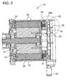
- a motor of one embodiment of the invention is generally designated 11.
- the motor 11 generally comprises a housing 13, a stator 15 mounted within the housing, and a rotor 17 in magnetic coupling relation with the stator.
- the configuration of the motor can vary within the scope of the invention.
- the stator 15 includes teeth 19, and windings 21 of the motor 11 are wound around the teeth of the stator.
- potting material 23 encases at least a portion of the windings 21.
- the motor 11 has a drive end (DE) and a non-drive end (NDE).
- the non-drive end of the motor 11 includes an endshield 25 (more generally, a shield) having a plurality (e.g. 6) of holes 27 (see Fig. 4A ) therethrough. Note that other types and configurations of shield are contemplated including shields that are not disposed at an end of the motor.
- winding leads 29 extend from the windings 21 through the holes 27 in the shield 25 and are electrically, mechanically and thermally connected to a busbar 31. Heat tends to be conducted through the winding leads 29 from the windings 21.
- Electronic components 33 e.g., capacitors and power components
- the heat conducted by the winding leads 29 can damage the electronic components 33.
- the motor 11 includes a cooling system for cooling the motor.
- the system includes coolant ports 37 fluidly connected to a "cooling jacket” or coolant channels 39 in the motor 11.
- the coolant flows through a channel 39A in the endshield 25 and through the cooling jacket 39 in the motor housing 13.
- the endshield 25 and the cooling jacket 39 are fluidly connected.
- the direct coolant contact with the endshield 25 helps to cool the shield and the winding leads 29, reducing the amount of heat transmitted to the busbar and thereby protecting the electronic components 33 from heat damage.
- the cooling system 35 helps to maintain the electronic components 33 below a maximum acceptable temperature. In one embodiment, the maximum acceptable temperature is about 135°C.
- a variety of coolants may be suitable, including for example liquid coolant, gas refrigerants, or even high velocity air.
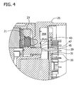
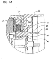
- a thermal connection between the winding leads and the shield is provided. Because the endshield 25 is actively cooled, e.g., in this embodiment, the endshield is thermally connected to the coolant, the winding leads 29 are cooled more effectively. Thus, less heat is conducted to the electronic components 33.
- the endshield 25 includes integral tubes 43 including the aforementioned holes 27 that receive the winding leads 29.
- the tubes 43 increase the surface area for heat transfer between the leads 29 and the endshield 25.
- the potting material 23 may include a post 45 extending up through the tubes 43 between the leads 29 and the tubes of the endshield 25.
- the potting material 23 serves to conduct heat from the leads 29 to the endshield 25.
- the leads 29 are both electrically insulated from the shield 25 and thermally connected to the endshield.
- a thermally conductive filler 47 such as RTV sealant, may be placed between the potting material 23 and the tube 43 of the shield 25.
- the endshield 25 is cast aluminum, and the potting material 23 is cast epoxy, though other materials and methods of manufacture are contemplated within the scope of the invention.
- the windings 21 are placed around the teeth of the stator 15, and the stator is placed in a mold.
- the liquid potting material 23 is poured into the mold and allowed to set. It is formed to create the final shape of the potted assembly, including the posts.
- the motor can have a variety of different rotor/stator constructions and a variety of different housings or even no housing separate from the stator.
- the motor need not include a cooling system, or even be actively cooled within the scope of this invention.
Landscapes
- Engineering & Computer Science (AREA)
- Power Engineering (AREA)
- Microelectronics & Electronic Packaging (AREA)
- Motor Or Generator Cooling System (AREA)
Priority Applications (1)
| Application Number | Priority Date | Filing Date | Title |
|---|---|---|---|
| EP07251988A EP1993191A1 (de) | 2007-05-15 | 2007-05-15 | Kühlung für eine elektrische Maschine |
Applications Claiming Priority (1)
| Application Number | Priority Date | Filing Date | Title |
|---|---|---|---|
| EP07251988A EP1993191A1 (de) | 2007-05-15 | 2007-05-15 | Kühlung für eine elektrische Maschine |
Publications (1)
| Publication Number | Publication Date |
|---|---|
| EP1993191A1 true EP1993191A1 (de) | 2008-11-19 |
Family
ID=38180124
Family Applications (1)
| Application Number | Title | Priority Date | Filing Date |
|---|---|---|---|
| EP07251988A Withdrawn EP1993191A1 (de) | 2007-05-15 | 2007-05-15 | Kühlung für eine elektrische Maschine |
Country Status (1)
| Country | Link |
|---|---|
| EP (1) | EP1993191A1 (de) |
Cited By (4)
| Publication number | Priority date | Publication date | Assignee | Title |
|---|---|---|---|---|
| CN104184261A (zh) * | 2013-05-27 | 2014-12-03 | 株式会社安川电机 | 旋转电机 |
| FR3019405A1 (fr) * | 2014-03-27 | 2015-10-02 | Valeo Equip Electr Moteur | Machine electrique tournante a refroidissement optimise et procede de realisation d'une interface thermique correspondant |
| CN105322718A (zh) * | 2014-06-25 | 2016-02-10 | Em-动力有限责任公司 | 用于电动马达的柔性的冷却连接装置 |
| DE102014220201A1 (de) * | 2014-10-06 | 2016-04-07 | Bühler Motor GmbH | Elektronisch kommutierter Gleichstrommotor, insbesondere für eine Ölpumpe |
Citations (5)
| Publication number | Priority date | Publication date | Assignee | Title |
|---|---|---|---|---|
| EP0327338A2 (de) * | 1988-02-03 | 1989-08-09 | Mitsubishi Denki Kabushiki Kaisha | Fahrzeug-Wechselstromgenerator und Herstellungsverfahren |
| FR2711283A1 (fr) * | 1993-10-13 | 1995-04-21 | Valeo Equip Electr Moteur | Alternateur de véhicule à refroidissement amélioré. |
| US5677616A (en) * | 1995-06-02 | 1997-10-14 | Nippondenso Co., Ltd. | Rectifying and voltage regulating unit of AC generator and method of making the same |
| DE19823769A1 (de) * | 1998-05-28 | 1999-12-02 | Bosch Gmbh Robert | Elektrische Maschine, insbesondere Drehstromgenerator |
| WO2005078900A1 (en) * | 2004-02-06 | 2005-08-25 | Emerson Electric Co. | Cooling system for dynamoelectric machine |
-
2007
- 2007-05-15 EP EP07251988A patent/EP1993191A1/de not_active Withdrawn
Patent Citations (5)
| Publication number | Priority date | Publication date | Assignee | Title |
|---|---|---|---|---|
| EP0327338A2 (de) * | 1988-02-03 | 1989-08-09 | Mitsubishi Denki Kabushiki Kaisha | Fahrzeug-Wechselstromgenerator und Herstellungsverfahren |
| FR2711283A1 (fr) * | 1993-10-13 | 1995-04-21 | Valeo Equip Electr Moteur | Alternateur de véhicule à refroidissement amélioré. |
| US5677616A (en) * | 1995-06-02 | 1997-10-14 | Nippondenso Co., Ltd. | Rectifying and voltage regulating unit of AC generator and method of making the same |
| DE19823769A1 (de) * | 1998-05-28 | 1999-12-02 | Bosch Gmbh Robert | Elektrische Maschine, insbesondere Drehstromgenerator |
| WO2005078900A1 (en) * | 2004-02-06 | 2005-08-25 | Emerson Electric Co. | Cooling system for dynamoelectric machine |
Cited By (6)
| Publication number | Priority date | Publication date | Assignee | Title |
|---|---|---|---|---|
| CN104184261A (zh) * | 2013-05-27 | 2014-12-03 | 株式会社安川电机 | 旋转电机 |
| FR3019405A1 (fr) * | 2014-03-27 | 2015-10-02 | Valeo Equip Electr Moteur | Machine electrique tournante a refroidissement optimise et procede de realisation d'une interface thermique correspondant |
| CN105322718A (zh) * | 2014-06-25 | 2016-02-10 | Em-动力有限责任公司 | 用于电动马达的柔性的冷却连接装置 |
| CN105322718B (zh) * | 2014-06-25 | 2019-02-05 | Em-动力有限责任公司 | 用于电动马达的柔性的冷却连接装置 |
| DE102014220201A1 (de) * | 2014-10-06 | 2016-04-07 | Bühler Motor GmbH | Elektronisch kommutierter Gleichstrommotor, insbesondere für eine Ölpumpe |
| US9948154B2 (en) | 2014-10-06 | 2018-04-17 | Buhler Motor Gmbh | Electronically commutated dc motor, in particular for an oil pump |
Similar Documents
| Publication | Publication Date | Title |
|---|---|---|
| US20070145836A1 (en) | Winding lead cooling for motor with heat-sensitive electronic components | |
| US7545060B2 (en) | Method and apparatus for heat removal from electric motor winding end-turns | |
| US9099900B2 (en) | Electric machine module cooling system and method | |
| CN101517859B (zh) | 半封闭式交流电动机 | |
| US8203240B2 (en) | Liquid cooled rotating electrical machine | |
| CN207098863U (zh) | 封闭式旋转电机以及同步磁阻电机 | |
| US7569955B2 (en) | Electric motor with heat pipes | |
| CN101919322B (zh) | 变换器电动机 | |
| JP5746417B2 (ja) | ポールシュー | |
| CN102428630B (zh) | 包覆模制的液体冷却三堆叠马达 | |
| US20160028284A1 (en) | Electric machine | |
| KR20130141502A (ko) | 전기 기계 고정자를 위한 냉각제 채널 | |
| CN108886301A (zh) | 具有冷却装置的电机 | |
| KR20110103955A (ko) | 전기 기계 및 이의 고정자부의 제조 방법 | |
| EP2605381A2 (de) | Elektromaschinenmodul-Kühlsystem und Verfahren | |
| KR20130079174A (ko) | 캡슐화 처리된 단부 턴을 구비한 전기 기계 | |
| US20170331345A1 (en) | Motor System | |
| US20130002067A1 (en) | Electric Machine Module Cooling System and Method | |
| EP1993191A1 (de) | Kühlung für eine elektrische Maschine | |
| CN105284032B (zh) | 电动机 | |
| JPH05111205A (ja) | 高周波発電機用の一体の水冷回路リング−母線アセンブリ | |
| US20240162786A1 (en) | Internal cooling systems for e-machines | |
| US11218058B2 (en) | Winding separators | |
| EP2421126A1 (de) | Stator mit Kühlanordnung | |
| KR101243291B1 (ko) | 공랭식 고정자코일 냉각장치 |
Legal Events
| Date | Code | Title | Description |
|---|---|---|---|
| PUAI | Public reference made under article 153(3) epc to a published international application that has entered the european phase |
Free format text: ORIGINAL CODE: 0009012 |
|
| AK | Designated contracting states |
Kind code of ref document: A1 Designated state(s): AT BE BG CH CY CZ DE DK EE ES FI FR GB GR HU IE IS IT LI LT LU LV MC MT NL PL PT RO SE SI SK TR |
|
| AX | Request for extension of the european patent |
Extension state: AL BA HR MK RS |
|
| AKX | Designation fees paid | ||
| REG | Reference to a national code |
Ref country code: DE Ref legal event code: 8566 |
|
| STAA | Information on the status of an ep patent application or granted ep patent |
Free format text: STATUS: THE APPLICATION IS DEEMED TO BE WITHDRAWN |
|
| 18D | Application deemed to be withdrawn |
Effective date: 20090520 |