EP1993667B1 - Applicateur portable pour la stimulation au collagène - Google Patents
Applicateur portable pour la stimulation au collagène Download PDFInfo
- Publication number
- EP1993667B1 EP1993667B1 EP06723469A EP06723469A EP1993667B1 EP 1993667 B1 EP1993667 B1 EP 1993667B1 EP 06723469 A EP06723469 A EP 06723469A EP 06723469 A EP06723469 A EP 06723469A EP 1993667 B1 EP1993667 B1 EP 1993667B1
- Authority
- EP
- European Patent Office
- Prior art keywords
- signal
- applicator according
- support body
- core coils
- applicator
- Prior art date
- Legal status (The legal status is an assumption and is not a legal conclusion. Google has not performed a legal analysis and makes no representation as to the accuracy of the status listed.)
- Expired - Lifetime
Links
Images



Classifications
-
- A—HUMAN NECESSITIES
- A61—MEDICAL OR VETERINARY SCIENCE; HYGIENE
- A61N—ELECTROTHERAPY; MAGNETOTHERAPY; RADIATION THERAPY; ULTRASOUND THERAPY
- A61N2/00—Magnetotherapy
- A61N2/02—Magnetotherapy using magnetic fields produced by coils, including single turn loops or electromagnets
Definitions
- the invention relates to a portable applicator for use in pulsatile signal therapy for the treatment of skin changes, for example due to skin aging or burn injuries, and in particular a portable applicator for use in pulsed signal therapy for stimulating collagen regeneration.
- the pulsating magnetic fields are applied to the corresponding body sites in a suitable strength and frequency for a certain period of time so that collagen-containing tissue systems of the body are excited.
- the human skin consists of several layers, the epidermis, the dermis and the subcutis.
- the skin is limited by the general body fascia, which consists of collagen fibers. Depending on the body region, either musculature, bones, cartilage or fat follow after the fascia.
- the dermis is an elastic skin layer, which is composed to a large extent of the structural proteins collagen and elastin. For example, it contains a dense network of collagen fibers filled with elastic connective tissue.
- Cartilage is a supporting tissue consisting of water-rich cartilage cells (chondrocytes) and intercellular substance. The extracellular matrix of cartilage consists of 60 to 80% water.
- the intercellular substance consists of ground substance (proteoglycans and glucoproteins) as well as Fibers (collagens) together.
- Proteoglycans, glucoproteins and collagens are produced by chondrocytes.
- the collagens form a network in which proteoglycans and glucoproteins are embedded and fixed.
- Type I, II, III, V and VI collagen molecules termed “fibrillar collagens” have similar molecular structures.
- Type IX, XII, and XIV collagen molecules called “fibril-associated collagens,” contain multiple triple helix domains that are interrupted by noncollagenous domains.
- Type V collagen molecules have a low alanine content but a high content of basic amino acids. In addition, they join together to form tetramers.
- Type VIII is a strong protease.
- Type IX is found on the surface of type II collagen.
- Collagen molecules of type XI are short triple helices with very long globular extensions.
- Type VII collagen molecules have an N-terminal domain region with three fingers, similar to collagen types XII and XIV.
- EP-A2-0244784 describes an electrotherapeutic magnetic field healing device to achieve a healing effect during everyday activities of a patient.
- the device contains a number of coils that are installed, for example, in a car seat.
- the coils are oriented parallel to the surface structure.
- the document contains no more detailed information.
- a portable applicator for this purpose, which has a carrier body and at least two signal generation arrangements, which are arranged in or on the carrier body.
- the at least two signal generating arrangements are connected in series, and each of the at least two signal generating arrangements comprises at least two core coils connected in parallel.
- an elevated treatment field can be provided precisely at the points where it is needed to stimulate collagen regeneration.
- the body parts to be treated need not be placed directly inside a coil, nor is a "Gegenpad” required, ie there are no two Coils are each provided at opposite locations, with the body part to be treated therebetween.
- the applicator of the present invention thus enables a more effective and targeted application of the magnetic field to the corresponding body parts.
- the portable applicator is advantageously easy to transport, such as in a suitcase or trolley.
- the applicator preferably has additional attachment means, such as e.g. Straps, straps, adhesive tapes, Velcro fasteners, etc., on.
- Each signal generation arrangement of the portable applicator preferably comprises three parallel-connected core coils.
- a parallel connection of three core coils is particularly advantageous since this number provides an optimal field distribution between the parallel-connected core coils, which ensures optimum use of the applicator.
- the coils are aligned with their longitudinal axis perpendicular to the surface structure of the carrier body in order to ensure a large penetration depth of the magnetic field into the skin.
- the core coils generate a pulsating magnetic field with a field strength of less than 25 Gauss (G), preferably 10-20 Gauss. At field strengths of this magnitude, it is ensured that the magnetic field is strong enough to penetrate through the fatty layer to the cartilage. In this way, cartilage cells and (connective) tissue are effectively stimulated by the applied magnetic field, whereby collagen formation is automatically stimulated.
- G Gauss
- the core coils are embedded in a protective body.
- the protective body is applied in the form of a coating directly on the core coils.
- the protective body is designed as a cap covering the core coils.
- the carrier body is surrounded by a sheath, which is preferably constructed of a biocompatible material.
- the sheath i. the body directly touching part of the portable applicator, made of a skin-friendly material.
- the sheath is formed of Neoprene®.
- the sheath is formed of latex.
- the carrier body is preferably an electrically insulating gel in which the signal generation arrangements are embedded.
- the use of a gel makes it possible to achieve optimal adaptability of the shape of the carrier body to the body part to be treated.
- the carrier body can be spread over a surface.
- the carrier body preferably has a shape corresponding to the respective body part to be treated. It is contemplated to design the shape of the carrier body so that it is suitable for the treatment of neck or Vietnamese dialect.
- the carrier body is designed as a face mask. Due to the configuration of the applicator as a face mask, the wrinkled or fold-prone areas of the face of a person to be treated can be exposed directly to the magnetic field, whereby a particularly efficient stimulation of collagen regeneration is achieved.
- the carrier body is designed in several parts.
- the carrier body consists of two mirror-symmetrical parts.
- the plurality of parts of the carrier body are articulated and / or elastically connected to each other.
- an optimal resting of the mask can be ensured, even in different people, each with different facial contours.
- the handleability is improved by the articulated or elastic connection of the carrier body parts.
- the mask can be folded or folded so that it occupies less space during transport or storage.
- a use according to the invention is characterized by the features of claim 11.
- this aspect of the present invention relates to the use of the above-described cosmetic skin treatment applicator.
- a cosmetic treatment includes both wellness and anti-aging treatments as well as the cosmetic treatment of wounds and scars.
- the new formation of collagen type II, IX, XI and X excited helps to improve the external appearance of the skin.
- a device according to the invention is characterized by the features of claim 13.
- a pulsatile signal therapy apparatus comprising the above-described applicator and means for supplying a control signal (controller) to the core coils.
- the applicator and controller are provided as a compact unit of equipment, i. the applicator is fixedly connected to the controller and / or the applicator and the controller are provided as an integral unit in a common housing.
- this device unit can be arranged in a suitcase or trolley.
- the controller is detachable from the applicator. Also in this embodiment, it is contemplated to provide the device for better transportation in a suitcase or trolley.
- control signal is a pulsed DC voltage at a rate of at most 30 pulses per second, more preferably 1 to 12 pulses per second, more preferably 5 to 12 pulses per second, and a rectangular pulse shape with an abruptly rising and abruptly decreasing voltage.
- the voltage is 24 V.
- the controller reduces the pulse width over the operating time and increases the number of pulses over the operating time.
- a portable applicator comprises a carrier body 10 and at least two signal generation arrangements 30, which are arranged in or on the carrier body 10, in particular in the example of FIG Fig. 1 shown.
- the at least two signal generation arrangements 30 are connected in series, and each of the at least two signal generation arrangements 30 comprises at least two core coils 20 connected in parallel.
- At least two signal generation arrangements 30, which in turn each have at least two core coils 20 connected in parallel, can achieve a more effective stimulation of collagen regeneration than with devices which are already known.
- an elevated treatment field ie a more targeted or local and more intensive magnetic field, can be provided precisely at the points where it is needed to stimulate the collagen regeneration.
- the magnetic fields of the individual core coils 20 overlap, wherein the distances between the individual core coils are adapted to the respective use.
- the superimposition reinforces the individual magnetic fields, and it is possible to generate a strong magnetic field in a small space, and with core coils of small dimensions.
- the invention is not limited to the fact that the magnetic fields of the individual core coils 20 overlap.
- the respective core coils 20 can also be arranged so far apart that the magnetic fields are no longer superimposed.
- the core coils 20 are placed farther apart in a large-area treatment of the skin, while they are arranged closer together in a punctual treatment. Surface treatment of the skin may be considered, for example, in the cosmetic treatment of scars.
- a scar can be regarded as a single "cell", for the treatment of which, in particular, a "broad-area” magnetic field, ie a less concentrated magnetic field, is suitable.
- a “broad-area” magnetic field ie a less concentrated magnetic field.
- a punctiform magnetic field that is, a very concentrated magnetic field
- a punctiform magnetic field lends itself to when there are many "cells" in a small area, such as in the area under the eyes.
- exemplary embodiments for a highly targeted and intensive skin treatment are embodiments 2 and 3 according to the invention, which are also described in detail below. It is clarified on the basis of these exemplary embodiments that the core coils 20 can be arranged corresponding to the respective requirements of the body sites to be treated (see, for example, US Pat Fig. 4 . 6 and 7 ).
- the core coils 20 are arranged very close together in the area under the eyes, since very many cells are concentrated in a small space, whereas the core coils 20 are arranged further apart from each other in the forehead area, since there is a lower concentration of cells in this area ,
- the distance in which the core coils are arranged relative to one another can thus be adapted to the structural structure of the skin surface to be treated, and thus to the special treatment requirements. Furthermore, the distance between the core coils is selected according to whether a superposition of the magnetic fields of the respective core coils is desired, and how large this overlay should be. If superposition of the magnetic fields of the individual core coils is desired, the properties of the core coils used, such as the dimensions and strength of the magnetic field, must be taken into account. Preferably, the distance between the individual core coils is between 0.5 times (eg in the area below the eyes) and 3 times (eg in the region of the forehead) the diameter of a core coil. Again One skilled in the art will be able to vary the distances between the individual core coils, depending on the requirement and the type of coils used.
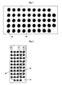
- Fig. 1 is a schematic representation of a first preferred embodiment of the portable applicator according to the invention.
- the applicator is spread flat (surface applicator).
- the surface applicator comprises a carrier body 10 and a plurality of core coils 20.
- a device for supplying a control signal to the core coils is also provided, but is incorporated in US Pat Fig. 1 Not shown.
- the applicator may be provided with conventional attachment means such as straps, straps, adhesive tapes, hook and loop fasteners, etc.
- the in Fig. 1 shown support body 10 is constructed of a flexible circuit board having a rectangular shape.
- the carrier body 10 may be formed of any suitable material and have any suitable shape, for example, depending on the particular body part on which the application is to be performed.
- the flat expandable carrier body 10 may have a rectangular shape with rounded corners, an oval shape, a round shape, or a kidney-shaped shape. The shape can be adapted to the respective body part on which the carrier body 10 is placed or which it encloses, in order to ensure optimum support of the carrier body 10 on the body appropriate body part to ensure.
- the support body is formed of a rigid material, it may be designed in several parts to allow better adaptability to the contour of the corresponding body part. These multiple parts may in turn be articulated or otherwise connected, eg with a strap, Velcro, etc. Possible areas of application of the planar applicator also extend to the neck or Vietnamese style.
- the carrier body 10 With regard to the material of the carrier body 10, both rigid and flexible and / or elastic materials are considered. In addition to the in Fig. 1 also shown are rigid or rigid printed circuit boards, flexible or elastic fabrics / fabrics and sheet-like structures made of rubber, and any material combinations thereof, considered.
- the carrier body 10 is made of Neoprene®.
- Other preferred materials for the support body 10 include latex and plastics, particularly preferably GVK, PP and / or PVC.
- it is considered to form the carrier body of a gel-like mass. That is to say that the signal generation units or treatment coils are preferably embedded in a mask which is filled with an electrically insulating gel and adapted to the respective body contour, similar to those for eye care. In this case, the carrier body of the respective contour / shape of the body part to be treated can be adapted particularly well.
- the signal generating units 20 are thus either attached to the carrier body 10 or embedded in it.
- the signal generating units 20 may additionally be embedded in or surrounded by a protective body (not shown).
- a protective body can cover both one and a plurality of core coils 20 at the same time, and may be formed, for example, in the form of an attachable to the core coils 20 cap.
- the term protective body encompasses all materials which are suitable for protecting the core coils 20, for example also protective lacquers and other coating materials.
- the carrier body 10 may also be covered or encased.
- the sheath (not shown) of the carrier body 10 may be one or more layers.
- the sheath may be constructed of at least three layers wherein an additional layer of material (e.g., fluid, gel, foam, etc.) conforming well to contours of the corresponding body part may be disposed between an inner and an outer cover layer.
- Suitable materials for the sheath of the support body 10 include, but are not limited to: fabrics, fabrics, neoprene®, rubber, plastics such as GVK, PP and / or PVC, as well as any material combinations thereof. Since the sheath comes into direct contact with the skin of the patient, the material of the sheath should be well tolerated by the skin.
- Air coils have no magnetically conductive core that amplifies the magnetic field and have only very small inductances.
- coils with a correspondingly large wire cross section are necessary, which are unsuitable for the present application. Since relatively small coils with a large inductance are desirable for the wellness / anti-aging application, so are coils with a core of a magnetizable material (eg ferrite or Iron powder core) used, which multiplies the inductance of the coil.
- a magnetizable material eg ferrite or Iron powder core
- the design of the core coil 20 is preferably upright / radial.
- Each individual coil may, for example, have the following characteristic values: 10,000 ⁇ H, +/- 10% tolerance at a test frequency of 10 kHz, max. 0.08A DC at 20 ° C.
- the coils should be aligned with their longitudinal axis perpendicular to the surface structure of the carrier body.
- the device for supplying a control signal (not shown) to the core coils 20 is preferably a control device with the following technical data: Input 100-200 VAC, 50-60 Hz, current consumption max. 2.2A; Output 24VDC, max. -30 Hz.
- the external structure of the controller i. its housing, can be configured adapted to the particular needs. For example, if the controller is portable, it may additionally include a carrying handle. In a control device which is intended to be installed in a device unit together with other devices, the housing may have additional means for attachment in the device unit.
- Fig. 2 is a schematic representation of the interconnection of in Fig. 1 surface applicator shown.
- the means for supplying a control signal is in Fig. 2 also not shown.
- a total of forty eight core coils 20 are attached to the carrier plate 10.
- Three core coils 20 in turn form a signal generation arrangement 30, so that a total of sixteen signal generation arrangements 30 are provided in this embodiment.
- the three core coils 20 of a signal generation arrangement 30 are connected in parallel, and the entirety of Signal generating devices 30 are connected in series.
- this particularly preferred embodiment relates to signal generation arrangements 30 of three core coils 20, those skilled in the art will understand that each of the signal generation arrangements 30 may consist of a different number of core coils 20.
- the core coils 30 consist of two or four or more signal generating units.
- FIG. 2 shown schematic representation of the surface applicator is divided into two connection pages. On each of the connection sides, a connection A or B is arranged. In addition, a common terminal C is provided. Although in Fig. 2 As shown, it is not necessary to arrange the same number of signal generation arrangements 30 on each connection side.
- a connecting cable for the electrical connection of the applicator which can be spread over the surface to the control unit can be supplied to the carrier body 10 by means of the preferably present sheathing of the carrier body, the connections A, B, C provided at any desired point.
- the core coils 20 generate a pulsating magnetic field with a field strength of less than 25 Gauss, preferably 10-20 Gauss.
- the strength of the resulting magnetic field is measured on the side of the applicator facing the body, and decreases with increasing distance from the applicator.
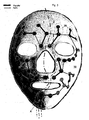
- FIG. 3 shown embodiment of the applicator according to the invention is specifically intended for a facial treatment. Same and similar parts as those in the Fig. 1 and 2 Embodiment 1 shown are denoted by the same reference numerals. In addition, will merely the differences between the two embodiments. With regard to the correspondence of the two embodiments, in structure and in function, reference is made to the above explanations to the embodiment 1 of the present invention.
- a carrier body 10 is divided by a dividing line I in a right half of the face 1 and a left half of the face 2.
- eight signal generating arrangements 30 connected in series, each comprising three core coils 20 connected in parallel, are arranged on each side 1, 2 of the face mask. That is, on each side 1, 2 of the face mask 24 core coils 20 are arranged, which are arranged on the face mask a total of 48 core coils 20.
- the core coils 20 are provided on the carrier body 10 for targeted stimulation of wrinkled or fold-prone regions of the face.
- the arrangement of the core coils 20 on the carrier body 10 takes place such that the core coils 20, with the mask applied, lie directly over the wrinkled or fold-prone areas of the face of the person to be treated.
- the two face halves 1, 2 are different in size in the embodiment shown, but they can also be the same size in their total area (see, eg Fig. 4 ).
- the face mask is integrally formed. Possible materials for the carrier body as well as a possible protective body or a casing have already been described with reference to the embodiment 1 according to the invention.
- the in Fig. 3 described face mask As well as those to be described below Embodiments of other face masks made of colored glass fiber reinforced plastic (GVK).
- the production can be done in half-shell technique, wherein the cavity between the half-shells, with the glued and interconnected core coils 20, with one-component polyurethane (PU) foam can be foamed to stabilize the mold / half-shells.
- Preferred production processes for the masks according to the invention are thermoforming or injection molding processes.
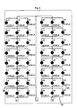
- a dividing line II divides the face mask into a right half of the face 1 and a left half of the face 2.
- both face halves 1, 2 are the same size, ie they have the same surface area.
- the two face halves 1, 2 can also be different in size.
- a plurality of core coils 20 are arranged on each face half 1, 2.
- the core coils 20 are arranged symmetrically on the support body 10 with respect to the parting line II.
- each signal generating arrangement 30 consisting of three core coils 20, mirror-symmetrically positioned to the nuclear coil separation line II.
- the arrangement of the individual core coils 20 can also be adapted to individual needs, so that, for example, an asymmetrical arrangement, or an arrangement with a different number of core coils 20 from each face half 1, 2, would be conceivable.
- the mask consists of two parts, wherein the number of parts is not limited to two.
- the two mask parts (or the two halves of the face 1, 2) can be hinged together to ensure optimum contact with the mask, with good manageability.
- the term "hinged connection” as used herein encompasses all types of connection by which one can effect turning, flipping, folding or pivoting of the plurality of parts relative to each other, either in one or more directions.
- connection options such as joints, hinges, pivots, etc. are taken into consideration.
- it may also be considered to provide not only hinged connections between the individual parts, but also / or elastic connections, eg, belts, belts, or other elastic means or materials in the interface region of the two face halves 1, 2.
- Fig. 3 and 4 shown face masks of the embodiment 2 according to the invention each comprise three terminals A, B and C, to provide a connection with a control device (not shown).
- the terminal A is provided for the core coils 20 of the right face half 1 of the face mask
- the terminal B is provided for the core coils 20 of the left face half 2
- the terminal C is a common terminal.
- the face mask according to the invention comprises on each side 1, 2 of the mask eight series-connected signal generating arrangements 30, each with three parallel core coils 20.
- the field distribution between the core coils 20 is optimal.
- all three core coils 20 also have a signal generation arrangement 30, the same inductance, so that each of the three parallel-connected core coils 20 has the same voltage.
- all arranged on the support body 10 core coils 20 have the same inductance.
- FIG. 6 and 7 different views of an embodiment 3 of the applicator according to the invention are shown.
- the embodiment 3 is also provided specifically for a facial treatment.
- the face mask of embodiment 3 provides an extended treatment field, as described in greater detail below.
- Same and similar parts as those in the Fig. 3 . 4 and 5 Embodiment 2 shown are designated by the same reference numerals.
- only the differences of the two embodiments will be discussed. With regard to the correspondence of the two embodiments, in structure and in function, reference is made to the above explanations to the embodiment 2 of the present invention.
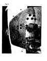
- a side view of the face mask according to Embodiment 3 is shown.
- the face mask according to Embodiment 3 is a plan view showing both face halves 1, 2.
- the face mask of embodiment 3 can also have one or more parts. If a multi-part shape of the face mask is selected (see Fig. 7 ), the various individual parts in turn can be connected to each other articulated and / or elastic (not shown). By means of the multi-part design of Facial mask, and the articulated and / or elastic connection of the individual parts, an optimal fit of the mask, with good manageability, can be ensured.
- the carrier body 10 of the right and left face halves 1, 2 each form a plurality of parts and made of different materials.
- the outer portion of the respective face half 1, 2, on which the additional 12 core coils 20 are arranged could be formed of a different material than the inner portion of the respective face half 1, 2, on which the remaining 48 core coils 20 are arranged.
- the embodiment 3 in addition to the 48 core coils core coils 20 already used in the embodiment 2, further 24 core coils 20 are provided.
- the additional 20 are - viewed from the center of the mask - outside of the Fig. 6 and 7 shown dashed lines.
- 4 signal generation arrangements 30 are arranged on each face half 1, 2 on a carrier body 10.
- the signal generation arrangements 30 each comprise three core coils 20.
- Fig. 8 is a schematic representation of the interconnection of in Fig. 7 illustrated third embodiment.
- the face mask with the extended treatment field is divided into three attachment sectors.
- terminals A and B are provided for a part of the signal generating devices 30, respectively.
- This part of the signal generating devices 30 corresponds to the number of signal generating devices 30 of the face mask of Embodiment 2, that is, the ports A and B are provided for the first 48 core coils 20 in total.
- an additional terminal D is provided for the other 24 core coils 20, ie 12 core coils 20 on each half of the face 1, 2 for the extended treatment field.
- a common terminal C is provided. The connection of the connections with a control unit is not shown.
- cosmetic skin treatment means both wellness and anti-aging treatments, as well as the cosmetic treatment of wounds and hubs.
- wellness treatment includes, inter alia, a cosmetic skin treatment to improve skin feel and to produce a radiant complexion.
- anti-aging treatment refers to a cosmetic skin treatment for reducing the depth of wrinkles and increasing the firmness of the skin. In general, the cosmetic anti-aging treatment thus results in a smoother and firmer appearance of the skin. Furthermore, also considering cosmetic treatments of wounds, scars and skin discoloration with the applicator according to the invention.
- skin discoloration is understood as meaning naturally occurring skin discolorations, such as, for example, age spots, as well as skin discolorations caused by trauma, for example due to hematomas or ecchymosis, or by a surgical or other procedure.
- the cosmetic treatment is suitable for both younger and older people. In particular, persons of average age tend to have fewer muscles, whereby maximum energy can be transmitted to the body sites to be treated.
- electromagnetic signals are used for cosmetic skin treatment.
- the electromagnetic signals are generated by a pulsating, pulse-modulated direct current, the frequency being between 1 and 30 Hz and the field strength is less than 25 Gauss, in particular between 10 and 20 Gauss.
- the cosmetic skin treatment with the portable applicator according to the invention is intended in particular to stimulate the formation of new collagen type II, IX, XI and X.
- a device for the pulsatile signal therapy comprises an applicator, as described in detail above, and a device for supplying a control signal (control device) to the signal generation units.
- the applicator and the controller are provided as a compact unit of equipment.
- the applicator is firmly connected to the control unit, for example screwed together, and / or the applicator and the control unit are provided as an integral unit in a common housing.
- the unit may also be provided in a suitcase or trolley to be transported easily.
- the controller is detachable from the applicator. Also in this embodiment, it is contemplated to provide the device for better transportation in a suitcase or trolley.
- the controller supplies the core coils 20 with a control signal, wherein the control signal is a pulsed DC voltage at a rate of a maximum of 30 pulses per second, preferably 1 to 12 pulses per second, more preferably 5 to 12 pulses per second, and a rectangular pulse shape an abruptly rising and abruptly decreasing voltage.
- the pulse width is reduced over the operating time, while the number of pulses is increased over the operating time.
- the pulse width is the respective pulse duration and the number of pulses is the number of pulses per unit of time, the data being given per port side, respectively.
- a cosmetic treatment lasts about one hour per session, with a total treatment time of 9 to 12 sessions.
- the control signal is output over a period of 1 h, with the highest pulse width and the lowest number of pulses being output in the first five minutes, a smaller pulse width and a higher number of pulses from the sixth to the tenth minute, and of the Eleventh to sixtieth minute will give the smallest pulse width and the highest number of pulses.
- the pulse width from the first to the fifth minute is 40-25 ms, particularly preferably 35-30 ms, from the sixth to the tenth minute 30-20 ms, particularly preferably 26-22 ms, and from the eleventh to the sixtieth minute 20-10 ms , especially 17-13ms.
- the number of pulses is from the first to the fifth minute 5 to 8, in particular 6, from the sixth to the tenth minute 8 to 10, in particular 9, and from the tenth to the sixtieth minute 10-12, in particular 11.
- the duty cycle also called duty cycle, indicates the ratio of the length of the switched-on state (pulse duration) to the period duration in the case of a square-wave signal. The resulting value multiplied by 100% gives the duty cycle in percent.
- the duty cycle from the first to the fifth minute is 15-21%, especially 17-20%, from the sixth to the tenth minute 20-25%, especially 21-23%, and from the tenth to the sixtieth 14-20% minute, in particular 15-17%.
- a therapeutic skin treatment may include the treatment of wounds and scars for therapeutic purposes, such as promoting the healing of wounds or the formation of smaller or "smoother" scars.
- Therapeutic skin treatment may include any type of skin treatment for therapeutic purposes in which stimulation of collagen regeneration has a positive effect on the appearance of the skin or the healing process.
- the portable applicator or device according to the present invention are also suitable for a number of medical purposes.
Landscapes
- Health & Medical Sciences (AREA)
- Engineering & Computer Science (AREA)
- Biomedical Technology (AREA)
- Nuclear Medicine, Radiotherapy & Molecular Imaging (AREA)
- Radiology & Medical Imaging (AREA)
- Life Sciences & Earth Sciences (AREA)
- Animal Behavior & Ethology (AREA)
- General Health & Medical Sciences (AREA)
- Public Health (AREA)
- Veterinary Medicine (AREA)
- Magnetic Treatment Devices (AREA)
- Electrotherapy Devices (AREA)
Claims (16)
- Applicateur portable pour thérapie par signaux pulsés, comprenant :un corps support (10) ; au moins deux dispositifs de génération de signaux (30) qui sont disposés dans ou au niveau du corps support (10), où les dispositifs de génération de signaux (30), au moins au nombre de deux,sont montés en série, et chacun des dispositifs de génération de signaux (30), au moins au nombre de deux, comporte au moins deux bobines à noyau (20) qui sont montées en parallèle, les bobines à noyau étant orientées par leur axe longitudinal perpendiculairement à la structure de surface du corps support.
- Applicateur portable selon la revendication 1, dans lequel chaque dispositif de génération de signaux (30) comporte trois bobines à noyau (20) montées en parallèle.
- Applicateur portable selon l'une des revendications précédentes, dans lequel les bobines à noyau (20) génèrent un champ magnétique pulsé présentant une intensité de champ inférieure à 25 G.
- Applicateur portable selon l'une des revendications précédentes, dans lequel les bobines à noyau (20) sont insérées dans un corps protecteur.
- Applicateur portable selon l'une des revendications précédentes, dans lequel le corps support (10) est entouré d'une enveloppe.
- Applicateur portable selon la revendication 5, dans lequel le corps support (10) est un gel électriquement isolant dans lequel sont insérés les dispositifs de génération de signaux (30).
- Applicateur portable selon l'une des revendications précédentes, dans lequel le corps support (10) peut s'étaler en nappe.
- Applicateur portable selon l'une des revendications 1 à 6, dans lequel le corps support (10) est exécuté en tant que masque pour visage.
- Applicateur portable selon la revendication 7 ou 8, dans lequel le corps support (10) est exécuté en plusieurs pièces.
- Applicateur portable selon la revendication 9, dans lequel les différentes pièces du corps support (10) sont reliées entre elles par articulation et/ou de façon élastique.
- Utilisation d'un applicateur selon l'une des revendications 1 à 10 pour un traitement cosmétique de la peau.
- Utilisation selon la revendication 11, dans laquelle on stimule la néoformation de collagène de type II, IX, XI et X.
- Dispositif de thérapie par signaux pulsés, comportant un applicateur selon l'une des revendications 1 à 10 et un dispositif permettant d'amener un signal de commande aux bobines à noyau (20).
- Dispositif selon la revendication 13, dans lequel le signal de commande est une tension continue pulsée selon une fréquence de 30 pulsations par seconde au maximum, de préférence de 1 à 12 pulsations par seconde, de façon particulièrement préférée de 5 à 12 pulsations par seconde, et une forme de pulsation rectangulaire avec une tension qui augmente de façon abrupte et chute de façon abrupte.
- Dispositif selon la revendication 14, dans lequel l'appareil de commande réduit la largeur d'impulsion sur la durée de fonctionnement et augmente le nombre d'impulsions sur la durée de fonctionnement.
- Dispositif selon l'une des revendications 13 et 14, dans lequel l'appareil de commande peut être détaché de l'applicateur.
Applications Claiming Priority (1)
| Application Number | Priority Date | Filing Date | Title |
|---|---|---|---|
| PCT/EP2006/002421 WO2007104340A1 (fr) | 2006-03-16 | 2006-03-16 | Applicateur portable pour la stimulation au collagène |
Publications (2)
| Publication Number | Publication Date |
|---|---|
| EP1993667A1 EP1993667A1 (fr) | 2008-11-26 |
| EP1993667B1 true EP1993667B1 (fr) | 2011-06-22 |
Family
ID=37400970
Family Applications (1)
| Application Number | Title | Priority Date | Filing Date |
|---|---|---|---|
| EP06723469A Expired - Lifetime EP1993667B1 (fr) | 2006-03-16 | 2006-03-16 | Applicateur portable pour la stimulation au collagène |
Country Status (11)
| Country | Link |
|---|---|
| US (1) | US20090270945A1 (fr) |
| EP (1) | EP1993667B1 (fr) |
| JP (1) | JP2009529387A (fr) |
| CN (1) | CN101437574A (fr) |
| AT (1) | ATE513581T1 (fr) |
| AU (1) | AU2006339921A1 (fr) |
| BR (1) | BRPI0621512A2 (fr) |
| CA (1) | CA2645144A1 (fr) |
| MX (1) | MX2008011824A (fr) |
| RU (1) | RU2403923C2 (fr) |
| WO (1) | WO2007104340A1 (fr) |
Families Citing this family (27)
| Publication number | Priority date | Publication date | Assignee | Title |
|---|---|---|---|---|
| ES2823288T3 (es) | 2008-06-29 | 2021-05-06 | Venus Concept Ltd | Aparato estético útil para aumentar el rejuvenecimiento de la piel |
| US9981143B2 (en) | 2008-06-29 | 2018-05-29 | Venus Concept Ltd. | Esthetic apparatus useful for increasing skin rejuvenation and methods thereof |
| DE102009060543B4 (de) * | 2009-12-23 | 2014-02-06 | Axel Muntermann | Verfahren zur kosmetischen Hautglättung |
| GB2486400B (en) * | 2010-11-20 | 2016-02-10 | Pulse Medical Technologies Ltd | Device for generating magnetic fields |
| DE102012013534B3 (de) | 2012-07-05 | 2013-09-19 | Tobias Sokolowski | Vorrichtung für repetitive Nervenstimulation zum Abbau von Fettgewebe mittels induktiver Magnetfelder |
| JP5605927B1 (ja) * | 2013-06-08 | 2014-10-15 | 株式会社ホーコーエン | 抗シワ用、コラーゲン収縮用、ヒアルロン酸増加用、細胞増殖用の美顔器・美容器 |
| US10105548B2 (en) * | 2014-12-03 | 2018-10-23 | Agas Yalee Concept Ltd. | Device for facial treatment based on light emission and induced magnetic field, and a system including same |
| US11491342B2 (en) | 2015-07-01 | 2022-11-08 | Btl Medical Solutions A.S. | Magnetic stimulation methods and devices for therapeutic treatments |
| US10695575B1 (en) | 2016-05-10 | 2020-06-30 | Btl Medical Technologies S.R.O. | Aesthetic method of biological structure treatment by magnetic field |
| US20180001107A1 (en) | 2016-07-01 | 2018-01-04 | Btl Holdings Limited | Aesthetic method of biological structure treatment by magnetic field |
| US11247039B2 (en) | 2016-05-03 | 2022-02-15 | Btl Healthcare Technologies A.S. | Device including RF source of energy and vacuum system |
| US11464993B2 (en) | 2016-05-03 | 2022-10-11 | Btl Healthcare Technologies A.S. | Device including RF source of energy and vacuum system |
| US11534619B2 (en) | 2016-05-10 | 2022-12-27 | Btl Medical Solutions A.S. | Aesthetic method of biological structure treatment by magnetic field |
| US10583287B2 (en) | 2016-05-23 | 2020-03-10 | Btl Medical Technologies S.R.O. | Systems and methods for tissue treatment |
| US10556122B1 (en) | 2016-07-01 | 2020-02-11 | Btl Medical Technologies S.R.O. | Aesthetic method of biological structure treatment by magnetic field |
| US11141219B1 (en) | 2016-08-16 | 2021-10-12 | BTL Healthcare Technologies, a.s. | Self-operating belt |
| US11541247B2 (en) * | 2018-01-04 | 2023-01-03 | George D. Hathaway | Magnetic stimulation probe |
| CN109011139A (zh) * | 2018-08-20 | 2018-12-18 | 广州无添加主义化妆品有限公司 | 微电流美容仪以及护肤仪器 |
| US12558146B2 (en) | 2019-04-11 | 2026-02-24 | Btl Medical Solutions A.S. | Methods and devices for aesthetic treatment of biological structures by radiofrequency and magnetic energy |
| PL4417249T3 (pl) | 2019-04-11 | 2026-04-20 | Btl Medical Solutions A.S. | Urządzenia do zabiegów na strukturach biologicznych za pomocą częstotliwości radiowej |
| US12156689B2 (en) | 2019-04-11 | 2024-12-03 | Btl Medical Solutions A.S. | Methods and devices for aesthetic treatment of biological structures by radiofrequency and magnetic energy |
| US12611545B2 (en) | 2020-05-04 | 2026-04-28 | Btl Healthcare Technologies A.S. | Device and method for unattended treatment of a patient |
| ES2993637T3 (en) | 2020-05-04 | 2025-01-03 | Btl Healthcare Technologies As | Device for unattended treatment of a patient |
| US11878167B2 (en) | 2020-05-04 | 2024-01-23 | Btl Healthcare Technologies A.S. | Device and method for unattended treatment of a patient |
| CA3260012A1 (fr) | 2021-10-13 | 2023-04-20 | Btl Medical Solutions A.S. | Dispositifs de traitement esthétique de structures biologiques par énergie radiofréquence et magnétique |
| US11896816B2 (en) | 2021-11-03 | 2024-02-13 | Btl Healthcare Technologies A.S. | Device and method for unattended treatment of a patient |
| US20260097227A1 (en) | 2024-10-08 | 2026-04-09 | Btl Medical Solutions A.S. | Devices and methods for application of a magnetic field to the nervous system |
Family Cites Families (9)
| Publication number | Priority date | Publication date | Assignee | Title |
|---|---|---|---|---|
| US4934383A (en) * | 1982-04-23 | 1990-06-19 | George Glumac | Electrode |
| EP0244784A3 (fr) * | 1986-05-09 | 1987-12-16 | Moshe Dr. Rosenthal | Dispositif électrothérapeutique |
| JPS6419453A (en) * | 1987-07-15 | 1989-01-23 | Fujitsu Ltd | Adapter controller |
| US5691325A (en) * | 1994-01-14 | 1997-11-25 | Sandyk; Reuven | Method for ameliorating age-related disease conditions |
| AU2229599A (en) * | 1998-01-15 | 1999-08-02 | Amethyst Technologies, Inc. | Improved pulsed electromagnetic energy treatment apparatus and method |
| US6463336B1 (en) * | 1999-04-01 | 2002-10-08 | Mmtc, Inc | Active bandage suitable for applying pulsed radio-frequencies or microwaves to the skin for medical purposes |
| ES2532134T3 (es) * | 2003-06-06 | 2015-03-24 | Telea Electronic Engineering S.R.L. | Dispositivo cosmético destinado al tratamiento del envejecimiento de la piel |
| US7914523B2 (en) * | 2004-02-06 | 2011-03-29 | Clinique Dr Daniel Barolet Inc. | Method for the treatment of mammalian tissues |
| FR2866240B1 (fr) * | 2004-02-16 | 2006-06-23 | Oreal | Kit de traitement comportant une structure composite a appliquer sur la peau et un excitateur electrique |
-
2006
- 2006-03-16 AT AT06723469T patent/ATE513581T1/de active
- 2006-03-16 RU RU2008140931/14A patent/RU2403923C2/ru not_active IP Right Cessation
- 2006-03-16 MX MX2008011824A patent/MX2008011824A/es active IP Right Grant
- 2006-03-16 CN CNA2006800545172A patent/CN101437574A/zh active Pending
- 2006-03-16 EP EP06723469A patent/EP1993667B1/fr not_active Expired - Lifetime
- 2006-03-16 JP JP2008558649A patent/JP2009529387A/ja active Pending
- 2006-03-16 AU AU2006339921A patent/AU2006339921A1/en not_active Abandoned
- 2006-03-16 WO PCT/EP2006/002421 patent/WO2007104340A1/fr not_active Ceased
- 2006-03-16 BR BRPI0621512-2A patent/BRPI0621512A2/pt not_active IP Right Cessation
- 2006-03-16 CA CA002645144A patent/CA2645144A1/fr not_active Abandoned
- 2006-03-16 US US12/225,165 patent/US20090270945A1/en not_active Abandoned
Also Published As
| Publication number | Publication date |
|---|---|
| BRPI0621512A2 (pt) | 2011-12-13 |
| RU2008140931A (ru) | 2010-04-27 |
| ATE513581T1 (de) | 2011-07-15 |
| AU2006339921A1 (en) | 2007-09-20 |
| MX2008011824A (es) | 2009-02-06 |
| RU2403923C2 (ru) | 2010-11-20 |
| US20090270945A1 (en) | 2009-10-29 |
| JP2009529387A (ja) | 2009-08-20 |
| CN101437574A (zh) | 2009-05-20 |
| CA2645144A1 (fr) | 2007-09-20 |
| EP1993667A1 (fr) | 2008-11-26 |
| WO2007104340A1 (fr) | 2007-09-20 |
Similar Documents
| Publication | Publication Date | Title |
|---|---|---|
| EP1993667A1 (fr) | Applicateur portable pour la stimulation au collagène | |
| DE2314573C2 (de) | Gerät zur Förderung von Heilungsprozessen | |
| DE69332033T2 (de) | Magnetotherapeutische vorrichtung | |
| EP2523726B1 (fr) | Stimulation magnétique au moyen d'une forme d'impulsion librement sélectionnable | |
| DE69030922T2 (de) | Elektrotherapeutisches gerät | |
| DE3788759T2 (de) | Therapeutische Vorrichtung mit Anwendung statischer Elektrizität. | |
| DE69304035T2 (de) | Medizinische vorrichtung | |
| DE69735761T2 (de) | Vorrichtung zur therapie mittels auf bestimmte krankheiten bezogenen niederfrequenz-signalen | |
| DE202007012438U1 (de) | Membranmaske für Akupunktur und Massage | |
| EP2113284B1 (fr) | Dispositif de stimulation d'un processus de guérison | |
| EP3145581B1 (fr) | Dispositif multicanaux de fourniture de courant continu utilisable à des fins thérapeutiques | |
| DE3340974C2 (de) | Elektrotherapiegerät | |
| DE202016008810U1 (de) | Magnetische Stimulationsvorrichtungen für therapeutische Behandlungen | |
| DE10237519A1 (de) | Magnetfeldtherapie | |
| DE4229693A1 (de) | Elektrotherapeutisches Gerät | |
| EP2021068B1 (fr) | Électrode de surface | |
| DE3437837A1 (de) | Geraet und verfahren zur elektrotherapeutischen selbstbehandlung des schmerzes und der schlaflosigkeit | |
| WO2015188811A1 (fr) | Dispositif et procédé de traitement du visage | |
| DE2552523A1 (de) | Elektrische vorrichtung zur regeneration und zum aufbau von kalkhaltigen geweben und knorpel | |
| DE69228745T2 (de) | Elektrisches System mit mehreren Signalen zur transdermalen Medikamentenverabreichung | |
| DE60025176T2 (de) | System zur schweissregulierung | |
| AT18188U1 (de) | Elektronische Vorrichtung zur Behandlung körperlicher ästhetischer Makel | |
| DE3716816C2 (fr) | ||
| DE2844980A1 (de) | Verfahren zum schutz vor iontophoretischen verbrennungen und zugehoerige vorrichtung | |
| AT371342B (de) | Elektrodenanordnung zur lokalen einleitung von gleichstrom in die haut eines lebenden koerpers, insbesondere zur iontophoretischen behandlung |
Legal Events
| Date | Code | Title | Description |
|---|---|---|---|
| PUAI | Public reference made under article 153(3) epc to a published international application that has entered the european phase |
Free format text: ORIGINAL CODE: 0009012 |
|
| 17P | Request for examination filed |
Effective date: 20080916 |
|
| AK | Designated contracting states |
Kind code of ref document: A1 Designated state(s): AT BE BG CH CY CZ DE DK EE ES FI FR GB GR HU IE IS IT LI LT LU LV MC NL PL PT RO SE SI SK TR |
|
| REG | Reference to a national code |
Ref country code: HK Ref legal event code: DE Ref document number: 1126153 Country of ref document: HK |
|
| GRAP | Despatch of communication of intention to grant a patent |
Free format text: ORIGINAL CODE: EPIDOSNIGR1 |
|
| DAX | Request for extension of the european patent (deleted) | ||
| GRAS | Grant fee paid |
Free format text: ORIGINAL CODE: EPIDOSNIGR3 |
|
| GRAA | (expected) grant |
Free format text: ORIGINAL CODE: 0009210 |
|
| AK | Designated contracting states |
Kind code of ref document: B1 Designated state(s): AT BE BG CH CY CZ DE DK EE ES FI FR GB GR HU IE IS IT LI LT LU LV MC NL PL PT RO SE SI SK TR |
|
| REG | Reference to a national code |
Ref country code: GB Ref legal event code: FG4D Free format text: NOT ENGLISH |
|
| REG | Reference to a national code |
Ref country code: CH Ref legal event code: EP |
|
| REG | Reference to a national code |
Ref country code: IE Ref legal event code: FG4D Free format text: LANGUAGE OF EP DOCUMENT: GERMAN |
|
| REG | Reference to a national code |
Ref country code: DE Ref legal event code: R096 Ref document number: 502006009707 Country of ref document: DE Effective date: 20110811 |
|
| REG | Reference to a national code |
Ref country code: NL Ref legal event code: VDEP Effective date: 20110622 |
|
| PG25 | Lapsed in a contracting state [announced via postgrant information from national office to epo] |
Ref country code: LT Free format text: LAPSE BECAUSE OF FAILURE TO SUBMIT A TRANSLATION OF THE DESCRIPTION OR TO PAY THE FEE WITHIN THE PRESCRIBED TIME-LIMIT Effective date: 20110622 Ref country code: SE Free format text: LAPSE BECAUSE OF FAILURE TO SUBMIT A TRANSLATION OF THE DESCRIPTION OR TO PAY THE FEE WITHIN THE PRESCRIBED TIME-LIMIT Effective date: 20110622 |
|
| PG25 | Lapsed in a contracting state [announced via postgrant information from national office to epo] |
Ref country code: SI Free format text: LAPSE BECAUSE OF FAILURE TO SUBMIT A TRANSLATION OF THE DESCRIPTION OR TO PAY THE FEE WITHIN THE PRESCRIBED TIME-LIMIT Effective date: 20110622 Ref country code: FI Free format text: LAPSE BECAUSE OF FAILURE TO SUBMIT A TRANSLATION OF THE DESCRIPTION OR TO PAY THE FEE WITHIN THE PRESCRIBED TIME-LIMIT Effective date: 20110622 Ref country code: LV Free format text: LAPSE BECAUSE OF FAILURE TO SUBMIT A TRANSLATION OF THE DESCRIPTION OR TO PAY THE FEE WITHIN THE PRESCRIBED TIME-LIMIT Effective date: 20110622 Ref country code: CY Free format text: LAPSE BECAUSE OF FAILURE TO SUBMIT A TRANSLATION OF THE DESCRIPTION OR TO PAY THE FEE WITHIN THE PRESCRIBED TIME-LIMIT Effective date: 20110622 Ref country code: GR Free format text: LAPSE BECAUSE OF FAILURE TO SUBMIT A TRANSLATION OF THE DESCRIPTION OR TO PAY THE FEE WITHIN THE PRESCRIBED TIME-LIMIT Effective date: 20110923 |
|
| PG25 | Lapsed in a contracting state [announced via postgrant information from national office to epo] |
Ref country code: NL Free format text: LAPSE BECAUSE OF FAILURE TO SUBMIT A TRANSLATION OF THE DESCRIPTION OR TO PAY THE FEE WITHIN THE PRESCRIBED TIME-LIMIT Effective date: 20110622 |
|
| REG | Reference to a national code |
Ref country code: IE Ref legal event code: FD4D |
|
| PG25 | Lapsed in a contracting state [announced via postgrant information from national office to epo] |
Ref country code: IE Free format text: LAPSE BECAUSE OF FAILURE TO SUBMIT A TRANSLATION OF THE DESCRIPTION OR TO PAY THE FEE WITHIN THE PRESCRIBED TIME-LIMIT Effective date: 20110622 Ref country code: CZ Free format text: LAPSE BECAUSE OF FAILURE TO SUBMIT A TRANSLATION OF THE DESCRIPTION OR TO PAY THE FEE WITHIN THE PRESCRIBED TIME-LIMIT Effective date: 20110622 Ref country code: IS Free format text: LAPSE BECAUSE OF FAILURE TO SUBMIT A TRANSLATION OF THE DESCRIPTION OR TO PAY THE FEE WITHIN THE PRESCRIBED TIME-LIMIT Effective date: 20111022 Ref country code: EE Free format text: LAPSE BECAUSE OF FAILURE TO SUBMIT A TRANSLATION OF THE DESCRIPTION OR TO PAY THE FEE WITHIN THE PRESCRIBED TIME-LIMIT Effective date: 20110622 Ref country code: PT Free format text: LAPSE BECAUSE OF FAILURE TO SUBMIT A TRANSLATION OF THE DESCRIPTION OR TO PAY THE FEE WITHIN THE PRESCRIBED TIME-LIMIT Effective date: 20111024 |
|
| PG25 | Lapsed in a contracting state [announced via postgrant information from national office to epo] |
Ref country code: RO Free format text: LAPSE BECAUSE OF FAILURE TO SUBMIT A TRANSLATION OF THE DESCRIPTION OR TO PAY THE FEE WITHIN THE PRESCRIBED TIME-LIMIT Effective date: 20110622 Ref country code: SK Free format text: LAPSE BECAUSE OF FAILURE TO SUBMIT A TRANSLATION OF THE DESCRIPTION OR TO PAY THE FEE WITHIN THE PRESCRIBED TIME-LIMIT Effective date: 20110622 Ref country code: PL Free format text: LAPSE BECAUSE OF FAILURE TO SUBMIT A TRANSLATION OF THE DESCRIPTION OR TO PAY THE FEE WITHIN THE PRESCRIBED TIME-LIMIT Effective date: 20110622 |
|
| PLBE | No opposition filed within time limit |
Free format text: ORIGINAL CODE: 0009261 |
|
| STAA | Information on the status of an ep patent application or granted ep patent |
Free format text: STATUS: NO OPPOSITION FILED WITHIN TIME LIMIT |
|
| 26N | No opposition filed |
Effective date: 20120323 |
|
| PG25 | Lapsed in a contracting state [announced via postgrant information from national office to epo] |
Ref country code: IT Free format text: LAPSE BECAUSE OF FAILURE TO SUBMIT A TRANSLATION OF THE DESCRIPTION OR TO PAY THE FEE WITHIN THE PRESCRIBED TIME-LIMIT Effective date: 20110622 |
|
| PG25 | Lapsed in a contracting state [announced via postgrant information from national office to epo] |
Ref country code: DK Free format text: LAPSE BECAUSE OF FAILURE TO SUBMIT A TRANSLATION OF THE DESCRIPTION OR TO PAY THE FEE WITHIN THE PRESCRIBED TIME-LIMIT Effective date: 20110622 |
|
| REG | Reference to a national code |
Ref country code: DE Ref legal event code: R097 Ref document number: 502006009707 Country of ref document: DE Effective date: 20120323 |
|
| BERE | Be: lapsed |
Owner name: BINDER MARKOLL, ERNESTINE Effective date: 20120331 |
|
| PG25 | Lapsed in a contracting state [announced via postgrant information from national office to epo] |
Ref country code: MC Free format text: LAPSE BECAUSE OF NON-PAYMENT OF DUE FEES Effective date: 20120331 |
|
| REG | Reference to a national code |
Ref country code: CH Ref legal event code: PL |
|
| GBPC | Gb: european patent ceased through non-payment of renewal fee |
Effective date: 20120316 |
|
| REG | Reference to a national code |
Ref country code: FR Ref legal event code: ST Effective date: 20121130 |
|
| PG25 | Lapsed in a contracting state [announced via postgrant information from national office to epo] |
Ref country code: CH Free format text: LAPSE BECAUSE OF NON-PAYMENT OF DUE FEES Effective date: 20120331 Ref country code: GB Free format text: LAPSE BECAUSE OF NON-PAYMENT OF DUE FEES Effective date: 20120316 Ref country code: BE Free format text: LAPSE BECAUSE OF NON-PAYMENT OF DUE FEES Effective date: 20120331 Ref country code: LI Free format text: LAPSE BECAUSE OF NON-PAYMENT OF DUE FEES Effective date: 20120331 Ref country code: FR Free format text: LAPSE BECAUSE OF NON-PAYMENT OF DUE FEES Effective date: 20120402 |
|
| PG25 | Lapsed in a contracting state [announced via postgrant information from national office to epo] |
Ref country code: ES Free format text: LAPSE BECAUSE OF FAILURE TO SUBMIT A TRANSLATION OF THE DESCRIPTION OR TO PAY THE FEE WITHIN THE PRESCRIBED TIME-LIMIT Effective date: 20111003 |
|
| REG | Reference to a national code |
Ref country code: AT Ref legal event code: MM01 Ref document number: 513581 Country of ref document: AT Kind code of ref document: T Effective date: 20120316 |
|
| PG25 | Lapsed in a contracting state [announced via postgrant information from national office to epo] |
Ref country code: BG Free format text: LAPSE BECAUSE OF FAILURE TO SUBMIT A TRANSLATION OF THE DESCRIPTION OR TO PAY THE FEE WITHIN THE PRESCRIBED TIME-LIMIT Effective date: 20110922 |
|
| PG25 | Lapsed in a contracting state [announced via postgrant information from national office to epo] |
Ref country code: AT Free format text: LAPSE BECAUSE OF NON-PAYMENT OF DUE FEES Effective date: 20120316 |
|
| PG25 | Lapsed in a contracting state [announced via postgrant information from national office to epo] |
Ref country code: TR Free format text: LAPSE BECAUSE OF FAILURE TO SUBMIT A TRANSLATION OF THE DESCRIPTION OR TO PAY THE FEE WITHIN THE PRESCRIBED TIME-LIMIT Effective date: 20110622 |
|
| PG25 | Lapsed in a contracting state [announced via postgrant information from national office to epo] |
Ref country code: LU Free format text: LAPSE BECAUSE OF NON-PAYMENT OF DUE FEES Effective date: 20120316 |
|
| PG25 | Lapsed in a contracting state [announced via postgrant information from national office to epo] |
Ref country code: HU Free format text: LAPSE BECAUSE OF FAILURE TO SUBMIT A TRANSLATION OF THE DESCRIPTION OR TO PAY THE FEE WITHIN THE PRESCRIBED TIME-LIMIT Effective date: 20060316 |
|
| REG | Reference to a national code |
Ref country code: HK Ref legal event code: WD Ref document number: 1126153 Country of ref document: HK |
|
| PGFP | Annual fee paid to national office [announced via postgrant information from national office to epo] |
Ref country code: DE Payment date: 20180329 Year of fee payment: 13 |
|
| REG | Reference to a national code |
Ref country code: DE Ref legal event code: R119 Ref document number: 502006009707 Country of ref document: DE |
|
| PG25 | Lapsed in a contracting state [announced via postgrant information from national office to epo] |
Ref country code: DE Free format text: LAPSE BECAUSE OF NON-PAYMENT OF DUE FEES Effective date: 20191001 |