EP1993706B1 - Psa-druckmessung und steuersystem - Google Patents
Psa-druckmessung und steuersystem Download PDFInfo
- Publication number
- EP1993706B1 EP1993706B1 EP07757990.2A EP07757990A EP1993706B1 EP 1993706 B1 EP1993706 B1 EP 1993706B1 EP 07757990 A EP07757990 A EP 07757990A EP 1993706 B1 EP1993706 B1 EP 1993706B1
- Authority
- EP
- European Patent Office
- Prior art keywords
- pressure
- channel
- vessels
- psa
- measured
- Prior art date
- Legal status (The legal status is an assumption and is not a legal conclusion. Google has not performed a legal analysis and makes no representation as to the accuracy of the status listed.)
- Not-in-force
Links
Images


Classifications
-
- B—PERFORMING OPERATIONS; TRANSPORTING
- B01—PHYSICAL OR CHEMICAL PROCESSES OR APPARATUS IN GENERAL
- B01D—SEPARATION
- B01D53/00—Separation of gases or vapours; Recovering vapours of volatile solvents from gases; Chemical or biological purification of waste gases, e.g. engine exhaust gases, smoke, fumes, flue gases, aerosols
- B01D53/02—Separation of gases or vapours; Recovering vapours of volatile solvents from gases; Chemical or biological purification of waste gases, e.g. engine exhaust gases, smoke, fumes, flue gases, aerosols by adsorption, e.g. preparative gas chromatography
- B01D53/04—Separation of gases or vapours; Recovering vapours of volatile solvents from gases; Chemical or biological purification of waste gases, e.g. engine exhaust gases, smoke, fumes, flue gases, aerosols by adsorption, e.g. preparative gas chromatography with stationary adsorbents
- B01D53/047—Pressure swing adsorption
-
- B—PERFORMING OPERATIONS; TRANSPORTING
- B01—PHYSICAL OR CHEMICAL PROCESSES OR APPARATUS IN GENERAL
- B01D—SEPARATION
- B01D2256/00—Main component in the product gas stream after treatment
- B01D2256/16—Hydrogen
-
- B—PERFORMING OPERATIONS; TRANSPORTING
- B01—PHYSICAL OR CHEMICAL PROCESSES OR APPARATUS IN GENERAL
- B01D—SEPARATION
- B01D2259/00—Type of treatment
- B01D2259/40—Further details for adsorption processes and devices
- B01D2259/40001—Methods relating to additional, e.g. intermediate, treatment of process gas
-
- B—PERFORMING OPERATIONS; TRANSPORTING
- B01—PHYSICAL OR CHEMICAL PROCESSES OR APPARATUS IN GENERAL
- B01D—SEPARATION
- B01D2259/00—Type of treatment
- B01D2259/40—Further details for adsorption processes and devices
- B01D2259/40007—Controlling pressure or temperature swing adsorption
- B01D2259/40009—Controlling pressure or temperature swing adsorption using sensors or gas analysers
-
- B—PERFORMING OPERATIONS; TRANSPORTING
- B01—PHYSICAL OR CHEMICAL PROCESSES OR APPARATUS IN GENERAL
- B01D—SEPARATION
- B01D2259/00—Type of treatment
- B01D2259/40—Further details for adsorption processes and devices
- B01D2259/40011—Methods relating to the process cycle in pressure or temperature swing adsorption
- B01D2259/40035—Equalization
- B01D2259/40039—Equalization with three sub-steps
-
- B—PERFORMING OPERATIONS; TRANSPORTING
- B01—PHYSICAL OR CHEMICAL PROCESSES OR APPARATUS IN GENERAL
- B01D—SEPARATION
- B01D2259/00—Type of treatment
- B01D2259/40—Further details for adsorption processes and devices
- B01D2259/40011—Methods relating to the process cycle in pressure or temperature swing adsorption
- B01D2259/40043—Purging
- B01D2259/4005—Nature of purge gas
- B01D2259/40052—Recycled product or process gas
-
- B—PERFORMING OPERATIONS; TRANSPORTING
- B01—PHYSICAL OR CHEMICAL PROCESSES OR APPARATUS IN GENERAL
- B01D—SEPARATION
- B01D2259/00—Type of treatment
- B01D2259/40—Further details for adsorption processes and devices
- B01D2259/40011—Methods relating to the process cycle in pressure or temperature swing adsorption
- B01D2259/40058—Number of sequence steps, including sub-steps, per cycle
- B01D2259/40075—More than ten
-
- B—PERFORMING OPERATIONS; TRANSPORTING
- B01—PHYSICAL OR CHEMICAL PROCESSES OR APPARATUS IN GENERAL
- B01D—SEPARATION
- B01D2259/00—Type of treatment
- B01D2259/40—Further details for adsorption processes and devices
- B01D2259/406—Further details for adsorption processes and devices using more than four beds
-
- B—PERFORMING OPERATIONS; TRANSPORTING
- B01—PHYSICAL OR CHEMICAL PROCESSES OR APPARATUS IN GENERAL
- B01D—SEPARATION
- B01D2259/00—Type of treatment
- B01D2259/40—Further details for adsorption processes and devices
- B01D2259/406—Further details for adsorption processes and devices using more than four beds
- B01D2259/4063—Further details for adsorption processes and devices using more than four beds using seven beds
-
- B—PERFORMING OPERATIONS; TRANSPORTING
- B01—PHYSICAL OR CHEMICAL PROCESSES OR APPARATUS IN GENERAL
- B01D—SEPARATION
- B01D2259/00—Type of treatment
- B01D2259/40—Further details for adsorption processes and devices
- B01D2259/406—Further details for adsorption processes and devices using more than four beds
- B01D2259/4066—Further details for adsorption processes and devices using more than four beds using nine beds
-
- B—PERFORMING OPERATIONS; TRANSPORTING
- B01—PHYSICAL OR CHEMICAL PROCESSES OR APPARATUS IN GENERAL
- B01D—SEPARATION
- B01D2259/00—Type of treatment
- B01D2259/40—Further details for adsorption processes and devices
- B01D2259/406—Further details for adsorption processes and devices using more than four beds
- B01D2259/4067—Further details for adsorption processes and devices using more than four beds using ten beds
-
- B—PERFORMING OPERATIONS; TRANSPORTING
- B01—PHYSICAL OR CHEMICAL PROCESSES OR APPARATUS IN GENERAL
- B01D—SEPARATION
- B01D2259/00—Type of treatment
- B01D2259/40—Further details for adsorption processes and devices
- B01D2259/414—Further details for adsorption processes and devices using different types of adsorbents
- B01D2259/4141—Further details for adsorption processes and devices using different types of adsorbents within a single bed
- B01D2259/4145—Further details for adsorption processes and devices using different types of adsorbents within a single bed arranged in series
-
- B—PERFORMING OPERATIONS; TRANSPORTING
- B01—PHYSICAL OR CHEMICAL PROCESSES OR APPARATUS IN GENERAL
- B01D—SEPARATION
- B01D53/00—Separation of gases or vapours; Recovering vapours of volatile solvents from gases; Chemical or biological purification of waste gases, e.g. engine exhaust gases, smoke, fumes, flue gases, aerosols
- B01D53/02—Separation of gases or vapours; Recovering vapours of volatile solvents from gases; Chemical or biological purification of waste gases, e.g. engine exhaust gases, smoke, fumes, flue gases, aerosols by adsorption, e.g. preparative gas chromatography
- B01D53/04—Separation of gases or vapours; Recovering vapours of volatile solvents from gases; Chemical or biological purification of waste gases, e.g. engine exhaust gases, smoke, fumes, flue gases, aerosols by adsorption, e.g. preparative gas chromatography with stationary adsorbents
- B01D53/0407—Constructional details of adsorbing systems
- B01D53/0446—Means for feeding or distributing gases
-
- B—PERFORMING OPERATIONS; TRANSPORTING
- B01—PHYSICAL OR CHEMICAL PROCESSES OR APPARATUS IN GENERAL
- B01D—SEPARATION
- B01D53/00—Separation of gases or vapours; Recovering vapours of volatile solvents from gases; Chemical or biological purification of waste gases, e.g. engine exhaust gases, smoke, fumes, flue gases, aerosols
- B01D53/02—Separation of gases or vapours; Recovering vapours of volatile solvents from gases; Chemical or biological purification of waste gases, e.g. engine exhaust gases, smoke, fumes, flue gases, aerosols by adsorption, e.g. preparative gas chromatography
- B01D53/04—Separation of gases or vapours; Recovering vapours of volatile solvents from gases; Chemical or biological purification of waste gases, e.g. engine exhaust gases, smoke, fumes, flue gases, aerosols by adsorption, e.g. preparative gas chromatography with stationary adsorbents
- B01D53/047—Pressure swing adsorption
- B01D53/053—Pressure swing adsorption with storage or buffer vessel
Definitions
- the present invention generally relates to pressure swing adsorption systems. More specifically, the present invention relates to a monitoring and control system for pressure swing adsorption systems.
- PSA Pressure swing adsorption
- a PSA apparatus usually includes multiple pressure vessels filled with a suitable adsorbent/adsorbents, with each vessel subsequently connected to two or more on-off valves that sequentially admit and expel gases at different pressures in order to affect the gas separation.
- the PSA cycle is defined by adjusting the time the vessel is open to the product channel relative to the time required to regenerate the adsorbent within each vessel. Given the cyclic nature of a PSA system, multiple vessels operating out of phase with each other is required to maintain constant product delivery. The regeneration stages often involve the exchange of gas between different vessels to perform pressure equalization and purge.
- An important aspect of multiple vessel PSA systems is the implementation of pressure equalization to conserve pressure energy.
- Pressure equalization is performed when gas from a first pressure vessel, at a high pressure, is directed through an on-off valve into a section of pipe (referred to here as the "equalization channel"), fills the equalization channel and is then directed into a second vessel, at a lower pressure, through a second on-off valve. During this pressure equalization stage all remaining on-off valves that connect other vessels to the equalization channel are closed.
- the first vessel, which is providing gas decreases in pressure
- the second vessel which is receiving gas
- the PSA system described in U.S. Patent No. 6,699,307 to Lomax et al. discloses a seven vessel PSA system with three pressure equalizations.
- a vessel at high pressure, p1 is opened to the equalization channel at the same time a vessel at a lower intermediate pressure, p3, opens to the equalization channel.
- the second pressure equalization stage opens the vessel that decreased in pressure to p2 to the equalization channel at the same time another vessel at a lower intermediate pressure, p4, opens to the equalization channel.
- the third pressure equalization stage opens the vessel that decreased in pressure to p3 to the equalization channel at the same time another vessel at a lower intermediate pressure, p6, opens to the equalization channel.
- the capacity of the adsorbent to retain the impurities in the adsorbed phase decreases according to the equilibrium isotherm and the composition front of each impurity continues to move towards the discharge end where gas is being withdrawn. It is a desirable condition of pressure equalization to prevent the breakthrough of impurities into the equalization channel by providing enough adsorbent mass to take up the propagation of these composition fronts.
- Purge is another important aspect of multiple vessel PSA systems to maintain purity of the product gas. If the purge is insufficient, then the impurities desorbed during the depressurization stage are not swept out of the void space, consequently polluting the product on the next production stage. However, if the purge is too great, then the volume of valuable product gas passed back through the vessel is in excess of that required to clean the void space of desorbed impurities at the desired purity level. Over purge results in an undesirable drop in product recovery.
- the vessel providing purge is progressively decreasing in pressure from some intermediate pressure, p4, to a final pressure, p5, where p4 > p5.
- the purge stage requires the ratio of purge-to-feed gas to be sufficient to maintain product purity, which requires p5 to be manipulated in order to attain the required volume of gas passed out of the providing vessel.
- breakthrough of gas impurities during pressure equalization is undesirable, a small amount of breakthrough can happen during purge as pressure further decreases to achieve the desired purge-to-feed ratio.
- a time-varying composition that starts relatively clean and progressively increases in impurity levels is passed into a pipe connecting these vessels (referred to here as the "purge channel").
- This gas which has been passed into the purge channel, is expanded across a flow constriction device and then directed into the top of a second vessel that has undergone depressurization and is at the lowest pressure of the cycle.
- the receive purge stage subsequently involves the sweeping of these impurities from the void space into the waste gas channel of the PSA system using gas directed from the provide purge vessel.
- the provide purge stream enriched in the lightly adsorbed component, further assists desorption of the impurities by reducing their concentration surrounding the adsorbent in the void space.
- the gas remaining in the purge channel at the end of the previous purge coupling is heavier in impurities than it was when the provide purge vessel first opened to the purge channel. Therefore, the section of the purge channel between the vessel providing and receiving purge must be flushed by pushing this initially impure gas into the receiving vessel until the flow of gas discharged from the provide purge vessel reaches the receiving vessel.
- the inventors have determined that if the distance between vessels providing and receiving purge is not held uniform, then the time-varying composition received into the receive purge vessel will also vary. The inventors have determined that his will result in one or several vessels in the system being out of balance with the others in terms of final axial composition through the vessel at the end of purge, potentially resulting in off-specification gas being sent to the product channel on the next production stage.
- Document EP 0 086 436 discloses a PSA system and method according to the preamble of claims 1 and 13.
- the present invention advantageously provides a pressure swing adsorption system as claimed in claim 1, in order to determine the performance of the cycle and monitor proper operation of the system.
- the present invention advantageously provides a system in which a controller can be used to monitor the PSA cycle performed within a module of the PSA system using only the at least one pressures measured by the at least one pressure measuring device, regardless of the number of vessels used in the module of the PSA system.
- the present invention further advanteageously provides a method of monitoring a PSA system,as defined in the set of claims.
- the present invention allows for the monitoring of the performance of the PSA cycle within a module using only the measured pressure within the at least one parallel channel, regardless of the number of vessels used in the module of the PSA system.
- the present invention further provides for controlling a discharge from a waste surge tank connected to the waste channel by using a measured pressure within the purge channel.
- the present invention also allows for determining a total number of vessels of the plurality of vessels used to perform the PSA cycle such that at least four vessels of the plurality of vessels are open to the feed channel during each stage of the PSA cycle.
- the present invention also allows for all stages of the PSA cycle to be configured to minimize a distance between a vessel of the plurality of vessels that is providing purge gas and a vessel of the plurality of vessels that is receiving the purge gas from the first vessel.
- a first aspect of the present invention provides that, from a control standpoint, it is critical to verify that each stage of the cycle has been properly performed and that the correct sequencing of opening and closing on-off valves to the equalization, purge and product channels has occurred.
- accurate and real-time knowledge of the pressure in each of the vessels in the PSA system can be used to:
- the use of one or more pressure measuring devices for each vessel can be used to achieve the desired goals, it disadvantageously increases cost and complexity.
- the inventors have determined that, with the vessels connected through parallel channels, such as the equalization, purge and product channels previously identified, only one pressure measuring device is needed for each parallel channel, i, in order to achieve the desired goals for any number of vessels, N, connected to the parallel channel(s), i.
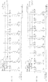
- three pressure measuring devices M1, M2, and M3 can be provided in the three parallel channels 130, 140, and 150 in the top head, as is depicted in FIG. 1A .
- the number of pressure measuring devices used in this configuration is three, which is advantageously less than half the number that would be required if one or more pressure measuring devices was provided for each vessel (i.e. seven vessels and seven pressure transducers) as in the related art.
- the invention can be applied to cycles that include any number of equalizations (e.g., one, two, three, etc.), and any number of vessels.
- the invention can be applied to a simple two equalization cycle in which only one or two sensors may be required to effectively monitor and control the system.
- the control system can advantageously be used in conjunction with a communication means, such as an Ethernet connection, to facilitate the remote monitoring of the operation of the PSA.
- the data received via the communication means can then be used to remotely identify the root cause of any observed failure mode.
- Such a remote monitoring operation can be used together with or independent of any local human machine interface, which would provide detailed fault codes based upon the information from the pressure sensors.
- each of the pressure measuring devices i, fluctuates between two well-defined pressure values, it is possible to use simple pressure switches in lieu of continuous pressure measuring device, such as pressure transducers.
- the use of simply pressure switches advantageously reduces the cost of the pressure measuring devices and allows for a simple, digital control system using the data from the pressure measuring devices, i, in combination with knowledge of the duration of the stages of the PSA cycle.
- Vessels performing purge should be as close as is practically possible to each other in the flowsheet.
- the present disclosure teaches that a logical cycle arrangement should be implemented to avoid a select number of vessels being a significant distance apart from the majority of purge couplings when the system contains a large number of vessels.
- the current disclosure proposes a PSA cycle for N vessels that is arranged as follows:
- the above aspect of the present invention provides improvements that are several fold in the control and operation of a multiple vessel PSA system.
- Table 1 compares these improvements in terms of the total number of pressure vessels required in the system that need to be filled with adsorbent and the number of pressure sensors that are required per number of vessels in the system.
- the associated complexity and cost associated with control and monitoring of the PSA system is reduced with the use of pressure sensors, i, for any number of vessels, N, in the system.
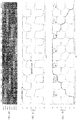
- the system monitors a continuously-varying pressure signal for each one of the vessels, examples of which can be seen in FIGS. 1D , 2D , 3D and 4D (note that the pressure trace for vessel 1 is in bold, and the other vessels have the same shape pressure trace, but which are staggered in time), for comparison with the present invention.
- FIGS. 1D , 2D , 3D and 4D note that the pressure trace for vessel 1 is in bold, and the other vessels have the same shape pressure trace, but which are staggered in time
- each of the pressure measuring devices, i, in the parallel channels records a pressure pulse for each vessel in its turn, examples of which can be seen in FIGS. 1C , 2C , 3C and 4C .
- the pressure measuring device M1 in the product channel 130 records a dip in pressure at each instance of the final pressurization stage.
- this dip in pressure will not be apparent at the appropriate time.
- the pressure as measured by the pressure measuring device M2 in the equalization channel 140 will cycle between a pressure, p2, achieved at the end of the first pressurization and a lower pressure, p3, achieved at the end of the second equalization.
- the pressure measuring device M3 in the purge channel 150 which is used to execute the third pressure equalization and purge stages, will record pressures that vary between the final equalization pressure, p4, and a pressure close to the lowest in the system, p6, due to throttling devices (not shown) in the purge channel 150.
- a control system for use with the pressure measuring devices can be used to monitor the pressures and correlate the pressures achieved in each of the three pressure measuring devices and identify suspected failures to notify an operator of the failure for maintenance, and possible reconfiguration until maintenance can be performed.
- the control system can even narrow down the possible failure points to valves associated only with the expected pressure change of the vessels in question.
- diagnostics can allow for possible reconfiguration of the system, for example, by switching the cycle arrangement so that the faulty valve/vessel is excluded from the cycle so that system can continue performing a PSA cycle until maintenance can be performed on the faulty component.
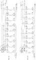
- FIGS. 1A-1C , 2A-2C , 3A-3C , and 4A-4C depict piping and instrumentation schematic diagrams for each PSA system layout with pressure measuring devices M1, M2 and M3 shown on the product channel 130, the equalization channel 140, and the purge channel 150, respectively.
- FIGS. 1B , 2B , 3B , and 4B show the resulting cycle arrangement for the respective PSA systems, and FIGS.
- FIGS. 1C , 2C , 3C , and 4C are graphs of pressure traces recorded from these respective arrangements. More specifically, FIGS. 1C , 2C , 3C , and 4C are graphs of pressure traces according to the present invention in which pressure measurement devices are provided in the product channel, equalization channel, and the purge channel of the PSA systems, shown in correspondence with their respective PSA cycle arrangement.
- FIGS. 1D , 2D , 3D , and 4D are graphs of pressure traces installed in the PSA systems using the related art method of including a pressure transducer in each vessel of the PSA system.
- the pressure trace for vessel 1 is in bold, and the other vessels have the same shape pressure trace as vessel 1 in their respective figure, but the traces of the other vessels are staggered in time as seen in the figures.
- These related art pressure traces are shown as a comparison to highlight the improvement in diagnostic ability and simplicity provided by the present invention.
- the pressure measuring devices of the present invention each cycle between their own relatively narrow, fixed pressure ranges (e.g., the product channel pressure measuring device M1 cycles generally between p2 and p1, the equalization channel pressure measuring device M2 cycles generally between p3 and p2, and the purge channel pressure measuring device M3 cycles generally between p6 and p4,) while each of the pressure transducers of the related art cycle all the way between p6 and p1. (Note that in the figures p6 ⁇ p5 ⁇ p4 ⁇ p3 ⁇ p2 ⁇ p1.)
- Valve tables associated with the four configurations depicted in FIGS. 1A, 2A , 3A, and 4A are shown in Tables 2-5, respectively, which indicate the on-off valves that are in an open state at various stages during the PSA cycles shown in FIGS. 1B , 2B , 3B , and 4B , respectively.
- Table 2 On-off valve table for seven vessel system in FIG. 1A using PSA cycle in FIG. 1B with three pressure equalizations. Any valve not listed above in a stage is closed during that stage.
- the present invention can be implemented in a variety of different PSA cycle configurations, for example, any variations in the number of pressure equalizations, initiating a period of feed or product repressurization during the "Final Press" stage, or any other variant around the purge coupling stages known to those skilled in the art can be utilized.
- Another advantage of the current aspect of the invention is the ability to have more vessels open to the feed channel for a modest increase in the total number of vessels within the system.
- the diameter of each vessel needs to be increased to handle the greater throughput of gas entering the feed channel.
- traditional methods used to hold the adsorbent down within the vessel in order to prevent fluidization become difficult and subsequent pellet attrition during PSA operation can occur.
- a novel scaling procedure disclosed in U.S. Patent No. 6,918,953 to Lomax et al. indicates that PSA capacity can be increased by adding additional PSA modules to the system.
- the concept behind this modular design is that a single PSA module that contains a specified number of vessels (such as a seven vessel PSA module) can process a certain volume of gas at the upper operating limit for a particular purity.
- the diameter of each vessel within a single PSA module is small enough to ensure vessel fluidization and channeling, which can arise in larger diameter vessels as a result of uneven adsorbent loading and settling, does not occur.
- Stepping up in throughput beyond the single PSA module requires the addition of more PSA modules, thereby increasing the volume of adsorbent available to invoke the desired PSA separation without changing the operating conditions present within each vessel.
- a two fold increase in the volume of gas that can be treated by a single PSA module requires the addition of a second PSA module.
- the addition of the second module means twice the volume of feed gas is split between twice the number of vessels (e.g., an increase from seven vessels to 14 vessels) open at any one time during the cycle so the specific conditions present within any one vessel do not change.
- each PSA module has two vessels open to the feed gas at any one point during the cycle, while the other five vessels are undergoing various stages of regeneration, such as pressure equalization, purge, or blowdown.
- applying the modular design means that doubling PSA capacity requires an additional seven vessel PSA module to be added to the system, thereby doubling the adsorbent inventory, number of pressure vessels, and associated fittings in the PSA system.
- the addition of the second module also introduces an additional level of complexity by adding thirty-five valves along with their associated pneumatic lines.
- FIG. 3B In contrast to the above scaling by adding additional modules, the present invention teaches that if, for example, an individual seven vessel PSA module were to be extended to a single nine vessel PSA module (e.g., by extending the top and bottom header sections to allow for two additional vessels), then four vessels are now advantageously open to the feed stream at any one point during the cycle, as can be seen by reviewing FIG. 3B .
- FIG. 3B and Table 4 indicate that valves 61, 71, 81, and 91 are open, thereby connecting vessels 6, 7, 8, and 9, respectively, to the feed channel 110 (see FIG. 3A ).
- the present invention has maintained the same volume of gas being processed per vessel, without introducing an entire second PSA module having seven additional vessels and thirty-five additional valves as required by the related art teaching.
- the present invention has reduced the adsorbent inventory by 36% by decreasing the total number of vessels from fourteen to nine.
- the total number of pressure sensors in the present invention is only three, while the related art system would require fourteen sensors.
- the reduction in the total number of pressure vessels also reduces the manufacturing and assembly costs in addition to the number of pressure vessels that require ASME approval.
- the above scaling rule of the present invention has the advantage of reducing complexity by reducing the number of on-off valves in the system, reducing the volume of adsorbent in the system, reducing the number of pressure vessels in the system, and reducing the number of external fittings required in the system, as compared to related art systems.
- the added ability of the present invention to include vessels into the manifold arrangement using the purge coupling procedure, in addition the present invention's ability to monitoring pressure pulses in each channel, rather than monitoring individual vessel pressure profiles as in the related art, allows the present invention to minimize the potential for imbalance in the system caused by differing purge channel distances between vessels or a valve failure.
- the purge channel pressure measuring device M3 (e.g. pressure transducer) shows the minimum pressure achieved during the depressurizing and purging of each PSA vessel. Whether the PSA module or modules are connected to a simple header, or to a buffer tank, it is desirable that the minimum pressure achieved in the depressurization of each vessel should be equal. Otherwise, the degree to which the adsorbed impurity species are desorbed and purged will vary. By using the minimum pressure achieved in the purge header transducer as a proxy for the pressure in the attached header and/or buffer tank, the use of a separate pressure transducer can be eliminated.
- the pressure in this header can be modulated through the use of a proportioning valve that meters the discharge from the header.
- a proportioning valve that meters the discharge from the header.
- Such a valve can be modulated to yield a constant average, maximum, or minimum pressure in the purge header, thus resulting in a stable oscillation.
- This metering valve is advantageously provided with a mechanical pressure regulating valve upstream of the inlet of the metering valve, such that the pressure at the metering valve inlet is essentially constant. This allows the variations in the instantaneous flowrate through the valve to be minimized, while the metering valve modulation maintains the average flowrate through the valve at a constant value by its response to the pressure input signal.
- One advantage in applying this control strategy in conjunction with the pressure measuring technique of the present invention arises when the PSA system 300 is used as a means of controlling a particular component of a hydrogen generating system.
- a reduction in complexity arises within the hydrogen generating system when the pressure measured within the purge channel (e.g., using purge channel pressure measuring device M3) is coupled to a proportional integral derivative (PID) controller C via wire 126 that regulates a volume of gas released from a waste gas tank 122 connected to the waste gas channel 120.
- PID proportional integral derivative
- the waste gas tank 122 is sized such that a relatively steady flow of gas can be withdrawn from the PSA system 300 to eliminate the pulsing nature of flow occurring at discrete time intervals associated with blowdown and purge, while, at the same time, minimizing any back-pressure imposed on the PSA system 300 when the receive purge vessel is open to the waste gas tank 122 via the waste gas channel 120.
- gas leaving the tank 122 is recycled to a burner 128 via line 124 to be used as fuel to heat a reactor 200 of the hydrogen generating system.
- the purpose of the PID controller C is to regulate the volume of gas withdrawn from the waste gas tank 122 such that the vessel undergoing the receive purge step (i.e. "Receive PG") remains at the desired low pressure.
- a transducer shown in phantom lines and labeled as 123 in FIG. 5
- an average of the pressure recorded by that transducer during blowdown and purge is used as the PID controlled variable by which adjustments are made to control a proportional valve 125 in line 124.
- the present invention advantageously allows for the elimination of the transducer 123 (thus depicted in phantom lines) and control of the proportional valve 125 using the PID controller C based on the lowest pressure achieved in the purge channel 150 as measured by pressure measuring device M3.
- the elimination of the transducer 123 results in a reduction in complexity of the hydrogen generating system.
- the reduction of the total number of pressure transducers in the hydrogen generating system by one reduces complexity without affecting operation or controllability of the hydrogen generating system.
- An additional advantage of the pressure measuring technique of the present invention arises when the pressure measurement in the product channel 130 (e.g., using the product channel pressure measuring device (M1)) is integrated with other components of the hydrogen generating system.
- an additional pressure transducer (shown in phantom lines and labeled as 112 in FIG. 6 ) is located after the reactor system 200 and is used to monitor pressure drop over the reactor 200 based on a difference in pressures between a location upstream of the reactor system 200 measured using a pressure transducer 114, and the pressure downstream of the reactor system 200 measured using pressure transducer 112. If a reactor tube was to become blocked (i.e.
- pressure transducer 112 located after the reactor is exposed to a hot and wet environment. During normal operation this gas is at a temperature close to 300°C, which can lead to high thermal stresses on sensitive internal components of the pressure transducer. After shutdown, water can become entrapped against the diaphragm of a pressure transducer that is exposed to the process gas. If ambient temperatures drop below freezing, this water will freeze and expand forming ice that can damage sensitive components connected to the diaphragm within the pressure transducer.
- the present invention provides a unique solution to these problems with the related art systems. Given that the majority of pressure drop occurs over the reactor and that the associated pressure drop through the condenser and PSA vessel is minor by comparison, the present invention allows for the elimination of pressure transducer 112 (thus depicted in phantom lines) by performing the calculation for reactor pressure drop based on the average of the high pressure measured in the product channel 130 of the PSA header. This configuration eliminates the need for a pressure transducer in-line after the reactor. This configuration results in an improvement in operational reliability and a reduction in hydrogen generating system complexity by using the product channel pressure transducer M1 for monitoring reactor pressure drop.
- a further advantage of the disclosed pressure measuring technique arises when the PSA system is to be started up or shut down using a pre-defined valve opening sequence.
- the product channel pressure transducer M1 can be used to verify the PSA system 300 goes through the desired rate of pressure increase with time for a select number of vessels that open to the product channel 130. If this rate of increase is too fast or too slow as compared to the desired rate of pressure increase, then a valve failure is likely to have occurred. Similarly, if a select number of vessels need to be equalized at some intermediate pressure following the product backfill stage, then the equalization channel pressure transducer M2 can be used to verify the required on-off valves opened and the desired pressure level is achieved.
- the sequence of stepping down vessel pressure to that of the waste gas channel 120 can be verified through the sequence of opening vessels to the equalization channel 140. Once all vessels have equalized in pressure to the waste gas channel 120, then purge can be initiated through the product channel 130 to remove impurities from the void space around adsorbent in each vessel to shut the PSA system 300 down in a clean state in readiness for the next start-up.
Landscapes
- Chemical & Material Sciences (AREA)
- Engineering & Computer Science (AREA)
- Analytical Chemistry (AREA)
- General Chemical & Material Sciences (AREA)
- Oil, Petroleum & Natural Gas (AREA)
- Chemical Kinetics & Catalysis (AREA)
- Separation Of Gases By Adsorption (AREA)
- Hydrogen, Water And Hydrids (AREA)
Claims (23)
- Ein Druckwechseladsorptions-, PSA-System, aufweisend:eine Vielzahl von Behältern (1-7) mit einer oder mehreren Schichten aus Adsorptionsmaterial darin;einen Zufuhrgaskanal (110), der mit der Vielzahl von Behältern über eine jeweilige erste Leitung mit einem ersten Ventil verbunden ist;einen Abfallkanal (120), der mit der Vielzahl von Behältern über eine jeweilige zweite Leitung mit einem zweiten Ventil verbunden ist;einen Produktkanal (130), der mit der Vielzahl von Behältern über eine jeweilige dritte Leitung mit einem dritten Ventil verbunden ist;einen Parallelkanal (140), der mit der Vielzahl von Behältern über eine jeweilige vierte Leitung mit einem vierten Ventil verbunden ist;eine erste Druckmessvorrichtung (M2), die konfiguriert ist, um einen Druck innerhalb des Parallelkanals zu messen; undeine Steuerung, die konfiguriert ist, um den von der ersten Druckmessvorrichtung während eines innerhalb des PSA-Systems durchgeführten PSA-Zyklus gemessenen Druck zu überwachen,dadurch gekennzeichnet, dass es ferner aufweist:eine zweite Druckmessvorrichtung (M1), die konfiguriert ist, um einen Druck innerhalb des Produktkanals (130) zu messen,wobei die Steuerung konfiguriert ist, um den von der zweiten Druckmessvorrichtung während des innerhalb des PSA-Systems durchgeführten PSA-Zyklus gemessenen Druck zu überwachen,einen Spülkanal (150), der mit der Vielzahl von Behältern über eine jeweilige fünfte Leitung mit einem fünften Ventil verbunden ist; undeine dritte Druckmessvorrichtung (M3), die konfiguriert ist, um einen Druck innerhalb des Spülkanals zu messen,wobei der Parallelkanal ein Ausgleichskanal ist,wobei die Steuerung konfiguriert ist, um den von der dritten Druckmessvorrichtung während des innerhalb des PSA-Systems durchgeführten PSA-Zyklus gemessenen Druck zu überwachen, undwobei die Steuerung konfiguriert ist, um den innerhalb des PSA-Systems durchgeführten PSA-Zyklus zu überwachen, lediglich unter Verwendung (i) der von der ersten Druckmessvorrichtung (M2) gemessenen Drücke, (ii) der von der ersten Druckmessvorrichtung (M2) und der zweiten Druckmessvorrichtung (M1) gemessenen Drücke, (iii) der von der ersten Druckmessvorrichtung (M2) und der dritten Druckmessvorrichtung (M3) gemessenen Drücke, oder (iv) der von der ersten Druckmessvorrichtung (M2), der zweiten Druckmessvorrichtung (M1) und der dritten Druckmessvorrichtung (M3) gemessenen Drücke.
- Das PSA-System nach Anspruch 1, ferner mit einem mit dem Abfallkanal verbundenen Abfallausgleichsbehälter.
- Das PSA-System nach Anspruch 2, wobei die Steuerung konfiguriert ist, um eine Entladung des Abfallausgleichsbehälters unter Verwendung des innerhalb des Spülkanals von der dritten Druckmessvorrichtung gemessenen Drucks zu steuern.
- Das PSA-System nach Anspruch 3, ferner mit einer Druckmessvorrichtung, die konfiguriert ist, um einen Druck innerhalb des Abfallausgleichsbehälters zu messen, wobei die Steuerung konfiguriert ist, um eine Entladung des Abfallausgleichsbehälters unter Verwendung des innerhalb des Abfallausgleichsbehälters gemessenen Drucks zu steuern.
- Das PSA-System nach Anspruch 1, wobei die Vielzahl von Behältern vier Behälter umfasst.
- Das PSA-System nach Anspruch 1, wobei die Vielzahl von Behältern sieben oder mehr Behälter umfasst.
- Das PSA-System nach Anspruch 1, wobei die erste Druckmessvorrichtung ein Druckschalter ist.
- Das PSA-System nach Anspruch 1, wobei die erste Druckmessvorrichtung ein Druckwandler ist.
- Ein Verfahren zum Überwachen eines Druckwechseladsorptions-(PSA)-Systems, das eine Vielzahl von Behältern (1-7) mit einer oder mehreren Schichten von Adsorptionsmaterial darin, einen Zufuhrgaskanal (110), der mit der Vielzahl von Behältern über eine jeweilige erste Leitung mit einem ersten Ventil verbunden ist, einen Abfallkanal (120), der mit der Vielzahl von Behältern über eine jeweilige zweite Leitung mit einem zweiten Ventil verbunden ist, einen Produktkanal (130), der mit der Vielzahl von Behältern über eine jeweilige dritte Leitung mit einem dritten Ventil verbunden ist, und einen Parallelkanal (140), der mit der Vielzahl von Behältern über eine jeweilige vierte Leitung mit einem vierten Ventil verbunden ist, umfasst, wobei das Verfahren aufweist:Durchführen eines PSA-Zyklus unter Verwendung der Vielzahl von Behältern;Messen eines Drucks innerhalb zumindest des Parallelkanals während des PSA-Zyklus; undÜberwachen der Leistung des PSA-Zyklus unter Verwendung des gemessenen Drucks innerhalb des Parallelkanals,dadurch gekennzeichnet, dass es ferner aufweist:Messen eines Drucks innerhalb des Produktkanals während des PSA-Zyklus, wobei das Überwachen der Leistung des PSA-Zyklus eine Verwendung des gemessenen Drucks innerhalb des Produktkanals umfasst,Messen eines Drucks innerhalb eines Spülkanals des PSA-Systems während des PSA-Zyklus, wobei der Spülkanal mit der Vielzahl von Behältern über eine jeweilige fünfte Leitung mit einem fünften Ventil verbunden ist,wobei der Parallelkanal ein Ausgleichskanal ist,wobei das Überwachen der Leistung des PSA-Zyklus eine Verwendung des gemessenen Drucks innerhalb des Spülkanals, des gemessenen Drucks innerhalb des Ausgleichskanals und des gemessenen Drucks innerhalb des Produktkanals umfasst, undwobei das Überwachen der Leistung des PSA-Zyklus lediglich unter Verwendung (i) der gemessenen Drücke innerhalb des Ausgleichskanals (140), (ii) der gemessenen Drücke innerhalb des Ausgleichskanals (140) und der gemessenen Drücke innerhalb des Produktkanals (130), (iii) der gemessenen Drücke innerhalb des Ausgleichskanals (140) und der gemessenen Drücke innerhalb des Spülkanals (150) oder (iv) der gemessenen Drücke innerhalb des Ausgleichskanals (140), der gemessenen Drücke innerhalb des Produktkanals (130) und der gemessenen Drücke innerhalb des Spülkanals (150) durchgeführt wird.
- Das Verfahren nach Anspruch 9, wobei der PSA-Zyklus einen oder mehrere Druckausgleiche umfasst.
- Das Verfahren nach Anspruch 9, ferner mit einem Steuern einer Entladung aus einem mit dem Abfallkanal verbundenen Abfallausgleichsbehälter unter Verwendung des gemessenen Drucks innerhalb des Spülkanals.
- Das Verfahren nach Anspruch 9, ferner mit einem Steuern einer Entladung aus einem mit dem Abfallkanal verbundenen Abfallausgleichsbehälter unter Verwendung eines innerhalb des Ausgleichsbehälters gemessenen Drucks.
- Das Verfahren nach Anspruch 9, wobei die Vielzahl von Behältern vier Behälter umfasst.
- Das Verfahren nach Anspruch 9, wobei die Vielzahl von Behältern sieben oder mehr Behälter umfasst.
- Das Verfahren nach Anspruch 9, wobei ein Druckschalter verwendet wird, um eine Druckmessung innerhalb des Parallelkanals durchzuführen.
- Das Verfahren nach Anspruch 9, wobei ein Druckwandler verwendet wird, um eine Druckmessung innerhalb des Parallelkanals durchzuführen.
- Das Verfahren nach Anspruch 9, wobei eine Gesamtzahl an Behältern aus der Vielzahl von Behältern, die zur Durchführung des PSA-Zyklus verwendet werden, so bestimmt wird, dass zumindest vier Behälter aus der Vielzahl von Behältern während jedes PSA-Zyklus zu dem Zufuhrkanal hin offen sind.
- Das Verfahren nach Anspruch 9, wobei ein Überwachen der Leistung des PSA-Zyklus ein Überwachen umfasst, ob der gemessene Druck innerhalb des Parallelkanals innerhalb eines vorbestimmten Bereichs liegt.
- Das Verfahren nach Anspruch 18, wobei, falls der gemessene Druck innerhalb des Parallelkanals außerhalb des vorbestimmten Bereichs liegt, eine Fehlfunktionsbestimmung erreicht wird.
- Das Verfahren nach Anspruch 9, wobei alle Stufen des PSA-Zyklus konfiguriert sind, um einen Abstand zwischen einem Behälter aus der Vielzahl von Behältern, der Spülgas bereitstellt, und einem Behälter aus der Vielzahl von Behältern, der das Spülgas aus dem ersten Behälter empfängt, zu minimieren.
- Das Verfahren nach Anspruch 20, wobei die Vielzahl von Behältern linear ausgerichtet und gleichmäßig voneinander beabstandet sind, und wobei alle Stufen des PSA-Zyklus so konfiguriert sind, dass der bereitstellende Spülgasbehälter und der empfangende Spülgasbehälter in jeder Stufe des PSA-Zyklus nicht mehr als einen weiteren Behälter dazwischen haben.
- Das Verfahren nach Anspruch 9, wobei beim Anfahren des PSA-Systems ein Druck in dem Produktkanal gemessen wird und eine tatsächliche Druckanstiegsrate des in dem Produktkanal gemessenen Drucks verwendet wird, um zu verifizieren, dass das PSA-System eine gewünschte Druckanstiegsrate mit der Zeit für eine ausgewählte Anzahl von Behältern aus der Vielzahl von Behältern durchläuft, die den Produktkanal während einer Stufe öffnen.
- Das Verfahren nach Anspruch 22, wobei, falls die tatsächliche Anstiegsrate nicht gleich zu der gewünschten Anstiegsrate ist, eine Fehlfunktionsbestimmung erreicht wird.
Applications Claiming Priority (2)
| Application Number | Priority Date | Filing Date | Title |
|---|---|---|---|
| US77891206P | 2006-03-06 | 2006-03-06 | |
| PCT/US2007/063395 WO2007103926A2 (en) | 2006-03-06 | 2007-03-06 | Psa pressure measurement and control system |
Publications (3)
| Publication Number | Publication Date |
|---|---|
| EP1993706A2 EP1993706A2 (de) | 2008-11-26 |
| EP1993706A4 EP1993706A4 (de) | 2010-07-21 |
| EP1993706B1 true EP1993706B1 (de) | 2020-07-29 |
Family
ID=38475804
Family Applications (1)
| Application Number | Title | Priority Date | Filing Date |
|---|---|---|---|
| EP07757990.2A Not-in-force EP1993706B1 (de) | 2006-03-06 | 2007-03-06 | Psa-druckmessung und steuersystem |
Country Status (13)
| Country | Link |
|---|---|
| US (1) | US7674319B2 (de) |
| EP (1) | EP1993706B1 (de) |
| JP (1) | JP5575399B2 (de) |
| KR (1) | KR101312883B1 (de) |
| CN (1) | CN101394912B (de) |
| AU (1) | AU2007223118B2 (de) |
| CA (1) | CA2643128C (de) |
| DK (1) | DK1993706T3 (de) |
| ES (1) | ES2833073T3 (de) |
| HU (1) | HUE052918T2 (de) |
| PL (1) | PL1993706T3 (de) |
| PT (1) | PT1993706T (de) |
| WO (1) | WO2007103926A2 (de) |
Families Citing this family (53)
| Publication number | Priority date | Publication date | Assignee | Title |
|---|---|---|---|---|
| CA2702758C (en) | 2007-11-12 | 2016-08-30 | Exxonmobil Upstream Research Company | Methods of generating and utilizing utility gas |
| US7722698B2 (en) | 2008-02-21 | 2010-05-25 | Delphi Technologies, Inc. | Method of determining the purity of oxygen present in an oxygen-enriched gas produced from an oxygen delivery system |
| US8075676B2 (en) | 2008-02-22 | 2011-12-13 | Oxus America, Inc. | Damping apparatus for scroll compressors for oxygen-generating systems |
| MY158840A (en) * | 2008-04-30 | 2016-11-15 | Exxonmobil Upstream Res Co | Method and apparatus for removal of oil from utility gas stream |
| WO2011139813A1 (en) | 2010-05-05 | 2011-11-10 | Lummus Technology Inc. | Staged blowdown of adsorbent bed |
| US8449649B2 (en) * | 2010-05-11 | 2013-05-28 | Idatech, Llc | Systems and methods for starting up pressure swing adsorption assemblies and hydrogen-producing fuel processing systems including the same |
| US9067168B2 (en) | 2010-05-28 | 2015-06-30 | Exxonmobil Upstream Research Company | Integrated adsorber head and valve design and swing adsorption methods related thereto |
| US8241401B2 (en) | 2010-11-02 | 2012-08-14 | Mitsubishi Polycrystalline Silicon America Corporation (MIPSA) | Apparatus and method for producing purified hydrogen gas by a pressure swing adsorption processes |
| TWI495501B (zh) | 2010-11-15 | 2015-08-11 | Exxonmobil Upstream Res Co | 動力分餾器及用於氣體混合物之分餾的循環法 |
| MY163007A (en) | 2011-03-01 | 2017-07-31 | Exxonmobil Upstream Res Co | Methods of removing contaminants from hydrocarbon stream by swing adsorption and related apparatus and systems |
| AU2012259377B2 (en) | 2011-03-01 | 2016-12-01 | Exxonmobil Upstream Research Company | Methods of removing contaminants from a hydrocarbon stream by swing adsorption and related apparatus and systems |
| AU2012223486A1 (en) | 2011-03-01 | 2013-08-15 | Exxonmobil Upstream Research Company | Apparatus and systems having a rotary valve assembly and swing adsorption processes related thereto |
| US9352269B2 (en) | 2011-03-01 | 2016-05-31 | Exxonmobil Upstream Research Company | Apparatus and systems having a rotary valve assembly and swing adsorption processes related thereto |
| WO2012118757A1 (en) | 2011-03-01 | 2012-09-07 | Exxonmobil Upstream Research Company | Apparatus and systems having a reciprocating valve head assembly and swing adsorption processes related thereto |
| EA201391255A1 (ru) | 2011-03-01 | 2014-02-28 | Эксонмобил Апстрим Рисерч Компани | Устройства и системы, имеющие компактную конфигурацию многочисленных слоев для цикловой адсорбции, и связанные с этим способы |
| US9358493B2 (en) | 2011-03-01 | 2016-06-07 | Exxonmobil Upstream Research Company | Apparatus and systems having an encased adsorbent contactor and swing adsorption processes related thereto |
| EP2524726A1 (de) * | 2011-05-18 | 2012-11-21 | Total S.A. | Energiearmes zyklisches PSA-Verfahren |
| CN104136905B (zh) * | 2012-02-22 | 2016-03-16 | 野猫发现技术公司 | 用于利用一体式气体组分测量装置进行气体吸附测量和气体混合的设备 |
| US9034078B2 (en) | 2012-09-05 | 2015-05-19 | Exxonmobil Upstream Research Company | Apparatus and systems having an adsorbent contactor and swing adsorption processes related thereto |
| EP2746884B1 (de) | 2012-12-24 | 2015-04-15 | Air Products And Chemicals, Inc. | Vorrichtung und Verfahren zur Überwachung und Steuerung zyklischer Verarbeitungseinheiten in einer stationären Anlagenumgebung |
| US9034084B2 (en) | 2013-03-27 | 2015-05-19 | Lummus Technology Inc. | Apparatus for distributing flow |
| JP6604950B2 (ja) * | 2013-12-20 | 2019-11-13 | コーニンクレッカ フィリップス エヌ ヴェ | 急速診断を備える酸素分離器 |
| CA3063636C (en) | 2014-07-25 | 2022-03-01 | Exxonmobil Upstream Research Company | Cyclical swing absorption process and system |
| SG10201912669TA (en) | 2014-11-11 | 2020-02-27 | Exxonmobil Upstream Res Co | High capacity structures and monoliths via paste imprinting |
| EP3229938A1 (de) | 2014-12-10 | 2017-10-18 | ExxonMobil Research and Engineering Company | Polymerfasern mit integriertem adsorbens in gepacktem bett und gewebeschütz sowie verfahren und vorrichtungen mit verwendung davon |
| EP3237091B1 (de) | 2014-12-23 | 2021-08-04 | ExxonMobil Upstream Research Company | Strukturierte adsorbierende betten und verfahren zur deren herstellung |
| SG11201707069QA (en) | 2015-05-15 | 2017-11-29 | Exxonmobil Upstream Res Co | Apparatus and system for swing adsorption processes related thereto comprising mid-bed purge systems |
| CA2979870C (en) | 2015-05-15 | 2019-12-03 | Exxonmobil Upstream Research Company | Apparatus and system for swing adsorption processes related thereto |
| US10124286B2 (en) | 2015-09-02 | 2018-11-13 | Exxonmobil Upstream Research Company | Apparatus and system for swing adsorption processes related thereto |
| CN107847851B (zh) | 2015-09-02 | 2021-05-18 | 埃克森美孚上游研究公司 | 使用脱甲烷塔顶部流作为清扫气体的变化吸附方法和系统 |
| EA201891029A1 (ru) | 2015-10-27 | 2018-10-31 | Эксонмобил Апстрим Рисерч Компани | Устройство и система для процессов короткоцикловой адсорбции, имеющие множество клапанов |
| US10322365B2 (en) | 2015-10-27 | 2019-06-18 | Exxonmobil Upstream Reseach Company | Apparatus and system for swing adsorption processes related thereto |
| KR102119378B1 (ko) | 2015-10-27 | 2020-06-08 | 엑손모빌 업스트림 리서치 캄파니 | 능동 제어식 공급물 포핏 밸브 및 수동 제어식 생성물 밸브를 갖는 관련 스윙 흡착 공정용 장치 및 시스템 |
| EP3377194A1 (de) | 2015-11-16 | 2018-09-26 | Exxonmobil Upstream Research Company | Adsorptionsmaterialien und verfahren zur adsorption von kohlenstoffdioxid |
| RU2714063C1 (ru) | 2016-03-18 | 2020-02-11 | Эксонмобил Апстрим Рисерч Компани | Устройство и система для осуществления процессов короткоцикловой адсорбции |
| AU2017274289B2 (en) | 2016-05-31 | 2020-02-27 | Exxonmobil Upstream Research Company | Apparatus and system for swing adsorption processes |
| WO2017209860A1 (en) | 2016-05-31 | 2017-12-07 | Exxonmobil Upstream Research Company | Apparatus and system for swing adsorption processes |
| US10434458B2 (en) | 2016-08-31 | 2019-10-08 | Exxonmobil Upstream Research Company | Apparatus and system for swing adsorption processes related thereto |
| WO2018044501A1 (en) | 2016-09-01 | 2018-03-08 | Exxonmobil Upstream Research Company | Swing adsorption processes for removing water using 3a zeolite structures |
| US10328382B2 (en) | 2016-09-29 | 2019-06-25 | Exxonmobil Upstream Research Company | Apparatus and system for testing swing adsorption processes |
| AU2017379685B2 (en) | 2016-12-21 | 2020-03-12 | Exxonmobil Upstream Research Company | Self-supporting structures having foam-geometry structure and active materials |
| JP7021227B2 (ja) | 2016-12-21 | 2022-02-16 | エクソンモービル アップストリーム リサーチ カンパニー | 活性材料を有する自己支持構造 |
| WO2019147516A1 (en) | 2018-01-24 | 2019-08-01 | Exxonmobil Upstream Research Company | Apparatus and system for temperature swing adsorption |
| EP3758828A1 (de) | 2018-02-28 | 2021-01-06 | ExxonMobil Upstream Research Company | Vorrichtung und system für wechseladsorptionsprozesse |
| US11318410B2 (en) | 2018-12-21 | 2022-05-03 | Exxonmobil Upstream Research Company | Flow modulation systems, apparatus, and methods for cyclical swing adsorption |
| WO2020222932A1 (en) | 2019-04-30 | 2020-11-05 | Exxonmobil Upstream Research Company | Rapid cycle adsorbent bed |
| FR3096278B1 (fr) * | 2019-05-23 | 2021-09-10 | Air Liquide | Procédé de réglage d’une unité de production d’oxygène par comparaison des pressions différentielles caractéristiques des différents adsorbeurs |
| WO2021071755A1 (en) | 2019-10-07 | 2021-04-15 | Exxonmobil Upstream Research Company | Adsorption processes and systems utilizing step lift control of hydraulically actuated poppet valves |
| EP4045173A1 (de) | 2019-10-16 | 2022-08-24 | Exxonmobil Upstream Research Company (EMHC-N1-4A-607) | Verfahren zur entwässerung mit kationischem zeolith rho |
| FR3109100B1 (fr) * | 2020-04-09 | 2022-11-18 | Air Liquide | Procédé de gestion d’une unité de traitement d’un gaz par adsorption à modulation de pression |
| KR102144444B1 (ko) | 2020-06-25 | 2020-08-13 | 주식회사 한울엔지니어링 | 뉴럴 네트워크 기반 압력변동흡착장치 내 비정상 작동 감지 시스템 및 그 감지 방법 |
| WO2023049994A1 (en) | 2021-09-28 | 2023-04-06 | Iogen Corporation | Method and system for upgrading biogas using psa |
| JP2025171125A (ja) * | 2024-05-08 | 2025-11-20 | 大陽日酸株式会社 | ガス分離方法及びガス分離装置 |
Family Cites Families (17)
| Publication number | Priority date | Publication date | Assignee | Title |
|---|---|---|---|---|
| US3944400A (en) * | 1973-11-23 | 1976-03-16 | Petrocarbon Developments Limited | Method and apparatus for separating gases |
| US3986849A (en) | 1975-11-07 | 1976-10-19 | Union Carbide Corporation | Selective adsorption process |
| US4140495A (en) * | 1977-05-27 | 1979-02-20 | Union Carbide Corporation | Turndown control for pressure swing adsorption |
| DE2823211A1 (de) * | 1978-05-27 | 1979-12-06 | Bayer Antwerpen Nv | Verfahren zum betrieb einer druck- wechsel-adsorptionsanlage |
| DE2930782A1 (de) | 1979-07-28 | 1981-02-12 | Linde Ag | Verfahren zur adsorptiven reinigung oder zerlegung von gasgemischen |
| DE2951626C2 (de) * | 1979-12-21 | 1986-10-09 | Drägerwerk AG, 2400 Lübeck | Vorrichtung zum Zerlegen eines Gas-Gemisches |
| DE3205505A1 (de) * | 1982-02-16 | 1983-08-25 | Linde Ag, 6200 Wiesbaden | Verfahren zum betrieb einer zyklisch arbeitenden druckwechsel-adsorptionsanlage |
| US5051115A (en) * | 1986-05-21 | 1991-09-24 | Linde Aktiengesellschaft | Pressure swing adsorption process |
| US4761165A (en) * | 1987-09-01 | 1988-08-02 | Union Carbide Corporation | Pressure swing adsorption control method and apparatus |
| US5258056A (en) * | 1991-09-27 | 1993-11-02 | The Boc Group, Inc. | PSA system with product turndown and purity control |
| JPH05228322A (ja) * | 1992-02-19 | 1993-09-07 | Tokico Ltd | 気体分離装置 |
| US6394089B1 (en) * | 2000-01-18 | 2002-05-28 | Northrop Grumman Corporation | Patient ventilator oxygen concentration system |
| JP4531291B2 (ja) * | 2001-05-31 | 2010-08-25 | 東京瓦斯株式会社 | 水素精製用4塔式圧力スイング吸着装置の安定運転方法 |
| US6565628B2 (en) | 2001-07-23 | 2003-05-20 | Air Products And Chemicals, Inc. | Pressure swing adsorption process with reduced pressure equalization time |
| US6699307B1 (en) | 2002-10-11 | 2004-03-02 | H2Gen Innovations, Inc. | High recovery PSA cycles and apparatus with reduced complexity |
| JP2004218871A (ja) * | 2003-01-10 | 2004-08-05 | Hitachi Ltd | 深冷空気分離プラント |
| US6918953B2 (en) | 2003-07-09 | 2005-07-19 | H2Gen Innovations, Inc. | Modular pressure swing adsorption process and apparatus |
-
2007
- 2007-03-06 WO PCT/US2007/063395 patent/WO2007103926A2/en not_active Ceased
- 2007-03-06 AU AU2007223118A patent/AU2007223118B2/en not_active Ceased
- 2007-03-06 EP EP07757990.2A patent/EP1993706B1/de not_active Not-in-force
- 2007-03-06 ES ES07757990T patent/ES2833073T3/es active Active
- 2007-03-06 PL PL07757990.2T patent/PL1993706T3/pl unknown
- 2007-03-06 CA CA2643128A patent/CA2643128C/en active Active
- 2007-03-06 DK DK07757990.2T patent/DK1993706T3/da active
- 2007-03-06 KR KR1020087024422A patent/KR101312883B1/ko not_active Expired - Fee Related
- 2007-03-06 JP JP2008558504A patent/JP5575399B2/ja not_active Expired - Fee Related
- 2007-03-06 PT PT77579902T patent/PT1993706T/pt unknown
- 2007-03-06 HU HUE07757990A patent/HUE052918T2/hu unknown
- 2007-03-06 US US11/682,699 patent/US7674319B2/en active Active
- 2007-03-06 CN CN2007800079276A patent/CN101394912B/zh not_active Expired - Fee Related
Non-Patent Citations (1)
| Title |
|---|
| None * |
Also Published As
| Publication number | Publication date |
|---|---|
| ES2833073T3 (es) | 2021-06-14 |
| CA2643128A1 (en) | 2007-09-13 |
| US7674319B2 (en) | 2010-03-09 |
| CN101394912A (zh) | 2009-03-25 |
| DK1993706T3 (da) | 2020-11-02 |
| JP5575399B2 (ja) | 2014-08-20 |
| US20070204748A1 (en) | 2007-09-06 |
| KR101312883B1 (ko) | 2013-09-30 |
| CN101394912B (zh) | 2012-03-28 |
| EP1993706A4 (de) | 2010-07-21 |
| PT1993706T (pt) | 2020-11-23 |
| PL1993706T3 (pl) | 2021-03-22 |
| WO2007103926A2 (en) | 2007-09-13 |
| AU2007223118A1 (en) | 2007-09-13 |
| JP2009529410A (ja) | 2009-08-20 |
| WO2007103926A3 (en) | 2008-01-24 |
| KR20090004916A (ko) | 2009-01-12 |
| CA2643128C (en) | 2014-09-23 |
| HUE052918T2 (hu) | 2021-05-28 |
| AU2007223118B2 (en) | 2011-11-03 |
| EP1993706A2 (de) | 2008-11-26 |
Similar Documents
| Publication | Publication Date | Title |
|---|---|---|
| CA2643128C (en) | Psa pressure measurement and control system | |
| EP1880753B1 (de) | Druckwechseladsorptionsverfahren mit Lagerungen mit mehreren parallelen Behältern | |
| JP2009529410A5 (de) | ||
| US8828118B2 (en) | Staged blowdown of adsorbent bed | |
| AU2006204976A1 (en) | Methods and apparatus for improved control of PSA flow variations | |
| EP2411119A1 (de) | Steuerungsverfahren und steuerungsgerät für cyclische adsorption | |
| US7491260B2 (en) | Valve operation diagnostic method for pressure swing adsorption systems | |
| US6238458B1 (en) | Process for treatment of a gaseous mixture by pressure swing adsorption, with variable production flow rate | |
| CN113874097A (zh) | 用于调节针对每个吸附器具有不同设定点的氧气生产单元的方法 | |
| US4475930A (en) | Pressure swing adsorption system using product gas as replacement for purge gas | |
| CN111974162B (zh) | 用于通过比较不同吸附器的压差特征调节制氧单元的方法 | |
| JP4878326B2 (ja) | ガス製造装置 | |
| CN119139889A (zh) | 除氚系统和除氚方法 |
Legal Events
| Date | Code | Title | Description |
|---|---|---|---|
| PUAI | Public reference made under article 153(3) epc to a published international application that has entered the european phase |
Free format text: ORIGINAL CODE: 0009012 |
|
| 17P | Request for examination filed |
Effective date: 20080905 |
|
| AK | Designated contracting states |
Kind code of ref document: A2 Designated state(s): AT BE BG CH CY CZ DE DK EE ES FI FR GB GR HU IE IS IT LI LT LU LV MC MT NL PL PT RO SE SI SK TR |
|
| RAP1 | Party data changed (applicant data changed or rights of an application transferred) |
Owner name: LUMMUS TECHNOLOGY INC. |
|
| A4 | Supplementary search report drawn up and despatched |
Effective date: 20100617 |
|
| 17Q | First examination report despatched |
Effective date: 20100705 |
|
| DAX | Request for extension of the european patent (deleted) | ||
| STAA | Information on the status of an ep patent application or granted ep patent |
Free format text: STATUS: EXAMINATION IS IN PROGRESS |
|
| RIC1 | Information provided on ipc code assigned before grant |
Ipc: B01D 53/053 20060101ALN20200116BHEP Ipc: B01D 53/04 20060101ALN20200116BHEP Ipc: B01D 53/047 20060101AFI20200116BHEP |
|
| GRAP | Despatch of communication of intention to grant a patent |
Free format text: ORIGINAL CODE: EPIDOSNIGR1 |
|
| STAA | Information on the status of an ep patent application or granted ep patent |
Free format text: STATUS: GRANT OF PATENT IS INTENDED |
|
| INTG | Intention to grant announced |
Effective date: 20200224 |
|
| GRAS | Grant fee paid |
Free format text: ORIGINAL CODE: EPIDOSNIGR3 |
|
| GRAA | (expected) grant |
Free format text: ORIGINAL CODE: 0009210 |
|
| STAA | Information on the status of an ep patent application or granted ep patent |
Free format text: STATUS: THE PATENT HAS BEEN GRANTED |
|
| AK | Designated contracting states |
Kind code of ref document: B1 Designated state(s): AT BE BG CH CY CZ DE DK EE ES FI FR GB GR HU IE IS IT LI LT LU LV MC MT NL PL PT RO SE SI SK TR |
|
| REG | Reference to a national code |
Ref country code: GB Ref legal event code: FG4D |
|
| REG | Reference to a national code |
Ref country code: CH Ref legal event code: EP |
|
| REG | Reference to a national code |
Ref country code: AT Ref legal event code: REF Ref document number: 1295124 Country of ref document: AT Kind code of ref document: T Effective date: 20200815 |
|
| REG | Reference to a national code |
Ref country code: IE Ref legal event code: FG4D |
|
| REG | Reference to a national code |
Ref country code: DE Ref legal event code: R096 Ref document number: 602007060495 Country of ref document: DE |
|
| REG | Reference to a national code |
Ref country code: DK Ref legal event code: T3 Effective date: 20201029 |
|
| REG | Reference to a national code |
Ref country code: FI Ref legal event code: FGE |
|
| REG | Reference to a national code |
Ref country code: CH Ref legal event code: NV Representative=s name: SERVOPATENT GMBH, CH |
|
| REG | Reference to a national code |
Ref country code: NL Ref legal event code: FP |
|
| REG | Reference to a national code |
Ref country code: PT Ref legal event code: SC4A Ref document number: 1993706 Country of ref document: PT Date of ref document: 20201123 Kind code of ref document: T Free format text: AVAILABILITY OF NATIONAL TRANSLATION Effective date: 20201116 |
|
| REG | Reference to a national code |
Ref country code: SE Ref legal event code: TRGR |
|
| REG | Reference to a national code |
Ref country code: RO Ref legal event code: EPE |
|
| REG | Reference to a national code |
Ref country code: LT Ref legal event code: MG4D |
|
| REG | Reference to a national code |
Ref country code: GR Ref legal event code: EP Ref document number: 20200403009 Country of ref document: GR Effective date: 20201215 |
|
| PG25 | Lapsed in a contracting state [announced via postgrant information from national office to epo] |
Ref country code: BG Free format text: LAPSE BECAUSE OF FAILURE TO SUBMIT A TRANSLATION OF THE DESCRIPTION OR TO PAY THE FEE WITHIN THE PRESCRIBED TIME-LIMIT Effective date: 20201029 Ref country code: LT Free format text: LAPSE BECAUSE OF FAILURE TO SUBMIT A TRANSLATION OF THE DESCRIPTION OR TO PAY THE FEE WITHIN THE PRESCRIBED TIME-LIMIT Effective date: 20200729 |
|
| REG | Reference to a national code |
Ref country code: AT Ref legal event code: UEP Ref document number: 1295124 Country of ref document: AT Kind code of ref document: T Effective date: 20200729 |
|
| PG25 | Lapsed in a contracting state [announced via postgrant information from national office to epo] |
Ref country code: LV Free format text: LAPSE BECAUSE OF FAILURE TO SUBMIT A TRANSLATION OF THE DESCRIPTION OR TO PAY THE FEE WITHIN THE PRESCRIBED TIME-LIMIT Effective date: 20200729 |
|
| PG25 | Lapsed in a contracting state [announced via postgrant information from national office to epo] |
Ref country code: EE Free format text: LAPSE BECAUSE OF FAILURE TO SUBMIT A TRANSLATION OF THE DESCRIPTION OR TO PAY THE FEE WITHIN THE PRESCRIBED TIME-LIMIT Effective date: 20200729 Ref country code: IT Free format text: LAPSE BECAUSE OF FAILURE TO SUBMIT A TRANSLATION OF THE DESCRIPTION OR TO PAY THE FEE WITHIN THE PRESCRIBED TIME-LIMIT Effective date: 20200729 |
|
| PGFP | Annual fee paid to national office [announced via postgrant information from national office to epo] |
Ref country code: GR Payment date: 20210211 Year of fee payment: 15 Ref country code: FR Payment date: 20210210 Year of fee payment: 15 Ref country code: FI Payment date: 20210309 Year of fee payment: 15 |
|
| REG | Reference to a national code |
Ref country code: DE Ref legal event code: R097 Ref document number: 602007060495 Country of ref document: DE |
|
| REG | Reference to a national code |
Ref country code: HU Ref legal event code: AG4A Ref document number: E052918 Country of ref document: HU |
|
| PGFP | Annual fee paid to national office [announced via postgrant information from national office to epo] |
Ref country code: TR Payment date: 20210305 Year of fee payment: 15 Ref country code: IS Payment date: 20210208 Year of fee payment: 15 Ref country code: DE Payment date: 20210224 Year of fee payment: 15 Ref country code: DK Payment date: 20210310 Year of fee payment: 15 Ref country code: BE Payment date: 20210217 Year of fee payment: 15 |
|
| PLBE | No opposition filed within time limit |
Free format text: ORIGINAL CODE: 0009261 |
|
| STAA | Information on the status of an ep patent application or granted ep patent |
Free format text: STATUS: NO OPPOSITION FILED WITHIN TIME LIMIT |
|
| REG | Reference to a national code |
Ref country code: ES Ref legal event code: FG2A Ref document number: 2833073 Country of ref document: ES Kind code of ref document: T3 Effective date: 20210614 |
|
| PG25 | Lapsed in a contracting state [announced via postgrant information from national office to epo] |
Ref country code: SK Free format text: LAPSE BECAUSE OF FAILURE TO SUBMIT A TRANSLATION OF THE DESCRIPTION OR TO PAY THE FEE WITHIN THE PRESCRIBED TIME-LIMIT Effective date: 20200729 |
|
| 26N | No opposition filed |
Effective date: 20210430 |
|
| PG25 | Lapsed in a contracting state [announced via postgrant information from national office to epo] |
Ref country code: SI Free format text: LAPSE BECAUSE OF FAILURE TO SUBMIT A TRANSLATION OF THE DESCRIPTION OR TO PAY THE FEE WITHIN THE PRESCRIBED TIME-LIMIT Effective date: 20200729 |
|
| PG25 | Lapsed in a contracting state [announced via postgrant information from national office to epo] |
Ref country code: MC Free format text: LAPSE BECAUSE OF FAILURE TO SUBMIT A TRANSLATION OF THE DESCRIPTION OR TO PAY THE FEE WITHIN THE PRESCRIBED TIME-LIMIT Effective date: 20200729 |
|
| REG | Reference to a national code |
Ref country code: CH Ref legal event code: PL |
|
| PG25 | Lapsed in a contracting state [announced via postgrant information from national office to epo] |
Ref country code: CH Free format text: LAPSE BECAUSE OF NON-PAYMENT OF DUE FEES Effective date: 20210331 Ref country code: LU Free format text: LAPSE BECAUSE OF NON-PAYMENT OF DUE FEES Effective date: 20210306 Ref country code: IE Free format text: LAPSE BECAUSE OF NON-PAYMENT OF DUE FEES Effective date: 20210306 Ref country code: LI Free format text: LAPSE BECAUSE OF NON-PAYMENT OF DUE FEES Effective date: 20210331 |
|
| PGFP | Annual fee paid to national office [announced via postgrant information from national office to epo] |
Ref country code: HU Payment date: 20220129 Year of fee payment: 16 Ref country code: GB Payment date: 20220113 Year of fee payment: 16 Ref country code: AT Payment date: 20220225 Year of fee payment: 16 |
|
| REG | Reference to a national code |
Ref country code: ES Ref legal event code: FD2A Effective date: 20220523 |
|
| PGFP | Annual fee paid to national office [announced via postgrant information from national office to epo] |
Ref country code: SE Payment date: 20220110 Year of fee payment: 16 Ref country code: RO Payment date: 20220215 Year of fee payment: 16 Ref country code: PT Payment date: 20220307 Year of fee payment: 16 Ref country code: NL Payment date: 20220118 Year of fee payment: 16 |
|
| PG25 | Lapsed in a contracting state [announced via postgrant information from national office to epo] |
Ref country code: ES Free format text: LAPSE BECAUSE OF NON-PAYMENT OF DUE FEES Effective date: 20210307 |
|
| REG | Reference to a national code |
Ref country code: DE Ref legal event code: R119 Ref document number: 602007060495 Country of ref document: DE |
|
| REG | Reference to a national code |
Ref country code: FI Ref legal event code: MAE |
|
| REG | Reference to a national code |
Ref country code: DK Ref legal event code: EBP Effective date: 20220331 |
|
| PG25 | Lapsed in a contracting state [announced via postgrant information from national office to epo] |
Ref country code: FI Free format text: LAPSE BECAUSE OF NON-PAYMENT OF DUE FEES Effective date: 20220306 |
|
| REG | Reference to a national code |
Ref country code: BE Ref legal event code: MM Effective date: 20220331 |
|
| PG25 | Lapsed in a contracting state [announced via postgrant information from national office to epo] |
Ref country code: FR Free format text: LAPSE BECAUSE OF NON-PAYMENT OF DUE FEES Effective date: 20220331 Ref country code: DE Free format text: LAPSE BECAUSE OF NON-PAYMENT OF DUE FEES Effective date: 20221001 |
|
| PG25 | Lapsed in a contracting state [announced via postgrant information from national office to epo] |
Ref country code: GR Free format text: LAPSE BECAUSE OF NON-PAYMENT OF DUE FEES Effective date: 20221006 Ref country code: BE Free format text: LAPSE BECAUSE OF NON-PAYMENT OF DUE FEES Effective date: 20220331 |
|
| PG25 | Lapsed in a contracting state [announced via postgrant information from national office to epo] |
Ref country code: DK Free format text: LAPSE BECAUSE OF NON-PAYMENT OF DUE FEES Effective date: 20220331 |
|
| PGFP | Annual fee paid to national office [announced via postgrant information from national office to epo] |
Ref country code: CZ Payment date: 20230215 Year of fee payment: 17 |
|
| PG25 | Lapsed in a contracting state [announced via postgrant information from national office to epo] |
Ref country code: CY Free format text: LAPSE BECAUSE OF FAILURE TO SUBMIT A TRANSLATION OF THE DESCRIPTION OR TO PAY THE FEE WITHIN THE PRESCRIBED TIME-LIMIT Effective date: 20200729 |
|
| PGFP | Annual fee paid to national office [announced via postgrant information from national office to epo] |
Ref country code: PL Payment date: 20230109 Year of fee payment: 17 |
|
| PG25 | Lapsed in a contracting state [announced via postgrant information from national office to epo] |
Ref country code: RO Free format text: LAPSE BECAUSE OF NON-PAYMENT OF DUE FEES Effective date: 20230306 Ref country code: PT Free format text: LAPSE BECAUSE OF NON-PAYMENT OF DUE FEES Effective date: 20230906 |
|
| REG | Reference to a national code |
Ref country code: SE Ref legal event code: EUG |
|
| REG | Reference to a national code |
Ref country code: NL Ref legal event code: MM Effective date: 20230401 |
|
| REG | Reference to a national code |
Ref country code: AT Ref legal event code: MM01 Ref document number: 1295124 Country of ref document: AT Kind code of ref document: T Effective date: 20230306 |
|
| GBPC | Gb: european patent ceased through non-payment of renewal fee |
Effective date: 20230306 |
|
| PG25 | Lapsed in a contracting state [announced via postgrant information from national office to epo] |
Ref country code: NL Free format text: LAPSE BECAUSE OF NON-PAYMENT OF DUE FEES Effective date: 20230401 |
|
| PG25 | Lapsed in a contracting state [announced via postgrant information from national office to epo] |
Ref country code: GB Free format text: LAPSE BECAUSE OF NON-PAYMENT OF DUE FEES Effective date: 20230306 |
|
| PG25 | Lapsed in a contracting state [announced via postgrant information from national office to epo] |
Ref country code: SE Free format text: LAPSE BECAUSE OF NON-PAYMENT OF DUE FEES Effective date: 20230307 Ref country code: HU Free format text: LAPSE BECAUSE OF NON-PAYMENT OF DUE FEES Effective date: 20230307 Ref country code: GB Free format text: LAPSE BECAUSE OF NON-PAYMENT OF DUE FEES Effective date: 20230306 Ref country code: AT Free format text: LAPSE BECAUSE OF NON-PAYMENT OF DUE FEES Effective date: 20230306 |
|
| PG25 | Lapsed in a contracting state [announced via postgrant information from national office to epo] |
Ref country code: TR Free format text: LAPSE BECAUSE OF NON-PAYMENT OF DUE FEES Effective date: 20220306 Ref country code: MT Free format text: LAPSE BECAUSE OF FAILURE TO SUBMIT A TRANSLATION OF THE DESCRIPTION OR TO PAY THE FEE WITHIN THE PRESCRIBED TIME-LIMIT Effective date: 20200729 |
|
| PG25 | Lapsed in a contracting state [announced via postgrant information from national office to epo] |
Ref country code: CZ Free format text: LAPSE BECAUSE OF NON-PAYMENT OF DUE FEES Effective date: 20240306 |
|
| PG25 | Lapsed in a contracting state [announced via postgrant information from national office to epo] |
Ref country code: CZ Free format text: LAPSE BECAUSE OF NON-PAYMENT OF DUE FEES Effective date: 20240306 |
|
| PG25 | Lapsed in a contracting state [announced via postgrant information from national office to epo] |
Ref country code: PL Free format text: LAPSE BECAUSE OF NON-PAYMENT OF DUE FEES Effective date: 20240306 |
|
| PG25 | Lapsed in a contracting state [announced via postgrant information from national office to epo] |
Ref country code: IS Free format text: LAPSE BECAUSE OF NON-PAYMENT OF DUE FEES Effective date: 20221005 |