EP1993941B1 - Moyen de transport - Google Patents
Moyen de transport Download PDFInfo
- Publication number
- EP1993941B1 EP1993941B1 EP07702913.0A EP07702913A EP1993941B1 EP 1993941 B1 EP1993941 B1 EP 1993941B1 EP 07702913 A EP07702913 A EP 07702913A EP 1993941 B1 EP1993941 B1 EP 1993941B1
- Authority
- EP
- European Patent Office
- Prior art keywords
- lever
- conveying means
- roller
- means according
- toggle
- Prior art date
- Legal status (The legal status is an assumption and is not a legal conclusion. Google has not performed a legal analysis and makes no representation as to the accuracy of the status listed.)
- Not-in-force
Links
- 238000013461 design Methods 0.000 description 2
- 230000000694 effects Effects 0.000 description 2
- 230000007704 transition Effects 0.000 description 2
- 230000001154 acute effect Effects 0.000 description 1
- 238000013459 approach Methods 0.000 description 1
- 238000000071 blow moulding Methods 0.000 description 1
- 238000004891 communication Methods 0.000 description 1
- 238000010276 construction Methods 0.000 description 1
- 230000003247 decreasing effect Effects 0.000 description 1
- 230000001419 dependent effect Effects 0.000 description 1
- 238000011161 development Methods 0.000 description 1
- 230000018109 developmental process Effects 0.000 description 1
- 210000003414 extremity Anatomy 0.000 description 1
- 210000003127 knee Anatomy 0.000 description 1
- 238000002372 labelling Methods 0.000 description 1
- 238000012986 modification Methods 0.000 description 1
- 230000004048 modification Effects 0.000 description 1
- 238000004806 packaging method and process Methods 0.000 description 1
- 238000010008 shearing Methods 0.000 description 1
- 230000006641 stabilisation Effects 0.000 description 1
- 238000011105 stabilization Methods 0.000 description 1
- 210000003813 thumb Anatomy 0.000 description 1
Images


Classifications
-
- B—PERFORMING OPERATIONS; TRANSPORTING
- B65—CONVEYING; PACKING; STORING; HANDLING THIN OR FILAMENTARY MATERIAL
- B65G—TRANSPORT OR STORAGE DEVICES, e.g. CONVEYORS FOR LOADING OR TIPPING, SHOP CONVEYOR SYSTEMS OR PNEUMATIC TUBE CONVEYORS
- B65G21/00—Supporting or protective framework or housings for endless load-carriers or traction elements of belt or chain conveyors
- B65G21/16—Supporting or protective framework or housings for endless load-carriers or traction elements of belt or chain conveyors for conveyors having endless load-carriers movable in curved paths
- B65G21/18—Supporting or protective framework or housings for endless load-carriers or traction elements of belt or chain conveyors for conveyors having endless load-carriers movable in curved paths in three-dimensionally curved paths
-
- B—PERFORMING OPERATIONS; TRANSPORTING
- B65—CONVEYING; PACKING; STORING; HANDLING THIN OR FILAMENTARY MATERIAL
- B65G—TRANSPORT OR STORAGE DEVICES, e.g. CONVEYORS FOR LOADING OR TIPPING, SHOP CONVEYOR SYSTEMS OR PNEUMATIC TUBE CONVEYORS
- B65G17/00—Conveyors having an endless traction element, e.g. a chain, transmitting movement to a continuous or substantially-continuous load-carrying surface or to a series of individual load-carriers; Endless-chain conveyors in which the chains form the load-carrying surface
- B65G17/20—Conveyors having an endless traction element, e.g. a chain, transmitting movement to a continuous or substantially-continuous load-carrying surface or to a series of individual load-carriers; Endless-chain conveyors in which the chains form the load-carrying surface comprising load-carriers suspended from overhead traction chains
-
- B—PERFORMING OPERATIONS; TRANSPORTING
- B65—CONVEYING; PACKING; STORING; HANDLING THIN OR FILAMENTARY MATERIAL
- B65G—TRANSPORT OR STORAGE DEVICES, e.g. CONVEYORS FOR LOADING OR TIPPING, SHOP CONVEYOR SYSTEMS OR PNEUMATIC TUBE CONVEYORS
- B65G47/00—Article or material-handling devices associated with conveyors; Methods employing such devices
- B65G47/34—Devices for discharging articles or materials from conveyor
- B65G47/46—Devices for discharging articles or materials from conveyor and distributing, e.g. automatically, to desired points
- B65G47/51—Devices for discharging articles or materials from conveyor and distributing, e.g. automatically, to desired points according to unprogrammed signals, e.g. influenced by supply situation at destination
- B65G47/5104—Devices for discharging articles or materials from conveyor and distributing, e.g. automatically, to desired points according to unprogrammed signals, e.g. influenced by supply situation at destination for articles
- B65G47/5109—Devices for discharging articles or materials from conveyor and distributing, e.g. automatically, to desired points according to unprogrammed signals, e.g. influenced by supply situation at destination for articles first In - First Out systems: FIFO
- B65G47/5113—Devices for discharging articles or materials from conveyor and distributing, e.g. automatically, to desired points according to unprogrammed signals, e.g. influenced by supply situation at destination for articles first In - First Out systems: FIFO using endless conveyors
- B65G47/5118—Devices for discharging articles or materials from conveyor and distributing, e.g. automatically, to desired points according to unprogrammed signals, e.g. influenced by supply situation at destination for articles first In - First Out systems: FIFO using endless conveyors with variable accumulation capacity
- B65G47/5122—Devices for discharging articles or materials from conveyor and distributing, e.g. automatically, to desired points according to unprogrammed signals, e.g. influenced by supply situation at destination for articles first In - First Out systems: FIFO using endless conveyors with variable accumulation capacity by displacement of the conveyor-guiding means, e.g. of the loose pulley-type
-
- B—PERFORMING OPERATIONS; TRANSPORTING
- B65—CONVEYING; PACKING; STORING; HANDLING THIN OR FILAMENTARY MATERIAL
- B65G—TRANSPORT OR STORAGE DEVICES, e.g. CONVEYORS FOR LOADING OR TIPPING, SHOP CONVEYOR SYSTEMS OR PNEUMATIC TUBE CONVEYORS
- B65G2201/00—Indexing codes relating to handling devices, e.g. conveyors, characterised by the type of product or load being conveyed or handled
- B65G2201/02—Articles
- B65G2201/0235—Containers
- B65G2201/0244—Bottles
- B65G2201/0247—Suspended bottles
-
- B—PERFORMING OPERATIONS; TRANSPORTING
- B65—CONVEYING; PACKING; STORING; HANDLING THIN OR FILAMENTARY MATERIAL
- B65G—TRANSPORT OR STORAGE DEVICES, e.g. CONVEYORS FOR LOADING OR TIPPING, SHOP CONVEYOR SYSTEMS OR PNEUMATIC TUBE CONVEYORS
- B65G2207/00—Indexing codes relating to constructional details, configuration and additional features of a handling device, e.g. Conveyors
- B65G2207/24—Helical or spiral conveying path
Definitions
- the invention relates to a conveyor of the type described in the preambles of claim 1 and of claim 10.
- a subsidy of this kind is from the US Pat. No. 1,810,419 known.
- Another, out WO 2005/073113 known conveyor chain is used in a conveyor for the dynamic storage of objects.
- a conveyor designed as a conveyor chain is guided in a guide endlessly between an input station and a starting station.
- the conveyor chain acts in one area as a conveying strand and in another area as an empty strand, wherein the length of the conveying strand and the empty strand is variable and can be adapted to the amount of objects to be conveyed or stored.
- To vary the length of the conveyor run and the slack side a slide is provided which runs on mutually parallel areas of the guide.
- the carriage contains in each case an arcuate deflection for the conveying strand and for the empty strand, so that by moving the carriage along the guide regions, the proportion of the conveyor chain, which acts as a conveying strand, compared to the proportion of the empty strand can be increased or decreased.
- the conveyor chain is supported by rollers on the guide.
- at least a portion of the rollers be temporarily out of position Effect can be set to release the rollers from the guide and to guide the carriage or bring back from the carriage on the guide.
- at least one roller is designed to be pivotable, wherein the pivoting is done by means of a pivoting mechanism.
- a pawl which is biased by a torsion spring.
- the pawl cooperates with a transverse pin, which is arranged parallel to the axis of rotation and connected to the roller.
- the pawl is adapted to lock the roller in its engaged position with the guide when the pawl is engaged with the cross pin.
- the pawl is connected to an actuating thumb which is movable by a control surface associated with the carriage so that the pawl is moved against the force of the spring from its engagement with the cross pin and thus releases the roller for pivoting.
- the pivoted position of the roller is then defined by an arcuate cam groove on the carriage.
- the roller is pivoted back through the cam groove, whereupon the pawl is moved again with the cross pin in engagement, and locks the roller.
- the pawl must thus strike each pass of the carriage both in the conveying strand and in the slack side to the cross pin, which on the one hand causes unnecessary noise and on the other hand leads to increased wear.
- two cams are required, one for the pawls and one for the roller pivot.
- the invention is therefore based on the object to provide a conveyor chain of the type mentioned with an improved and simplified pivoting mechanism.
- the pivoting mechanism can be significantly simplified.
- the toggle can be connected directly to the roller lever of the roller, and must therefore not strike a pivot pin or other components for pivoting the roller.
- only one cam is required for the toggle.
- a knee lever continues to offer the decisive advantage that the lever members of the toggle lever only have to be locked in a certain relative position to each other for locking a specific position of the roller. This can be done by spring elements of various kinds, self-locking, magnetic elements or the like.
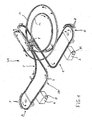
- the invention is described below with reference to a conveyor F with a dynamic memory V1, but can be used wherever it is necessary or advisable to pivot a roller of a conveyor controlled.
- the conveyor F is preferably arranged for conveying articles G, such as bottles of the containers, between different work stations, such as a stretch blow molding machine and a labeling machine or between a filling and closing machine and a packaging machine or the like, and essentially contains a single, endless conveying means 1 in the form of a roller chain, ie a provided with rollers limb or conveyor chain, for transporting Objects G.
- the conveyor 1 is guided by a stationary guide 2 such that it passes an input station E and an output station A.
- the conveyor 1 is driven in the region of the input station by a first drive device 3 with a motor M and in the region of the output station A by a second drive device 4 with a motor M.
- A is followed by a first, freely feasible area, in the illustrated embodiment, a langovaler area OV of the guide 2 at.
- the dynamic memory V1 further includes helical portions 2a, 2b of the guide 2, which are parallel and at a uniform distance from each other. On these areas 2a, 2b, a carriage 5 is movable, which in Fig. 2 is shown in more detail.
- the length of the conveying strand of the conveyor 1 between the input station E and the output station A can be adapted to the amount of objects to be conveyed to extend or shorten the originallyertrum compared to the Leerlauftrum between the output station A and the input station E.
- the carriage contains 5, as Fig. 2 shows a first 180 ° deflection 5a and a second 180 ° deflection 5b, which is opposite to the deflection 5a.
- Each deflection 5a, 5b connects opposite points of the parallel regions 2a, 2b of the guide 2 with one another in such a way that the conveying means can reach the region 2b from the region 2a.
- the first deflection 5a is associated with the delivery run and the second deflection 5b with the idle run.
- the carriage 5 is moved along the parallel portions 2a, 2b by a speed difference of the drive stations 3 and 4.
- the carriage 5 is moved by the conveyor 1 due to a corresponding difference in speed of the drive stations 3 and 4 in the direction of the input station E and the output station A.
- the carriage 5 of the input station E and the output station A is moved by a corresponding difference in speed of the drive stations 3 and 4, the carriage 5 of the input station E and the output station A.
- the conveyor 1 is supported, as Fig. 2 , right side, shows, on rollers 7 on the guide 2 from.
- the guide 2 may have any suitable shape, and may include, for example, two or more parallel rods, profiles of different cross sections or the like. It can continue, as in particular in Fig. 1 torsion points can be provided to pivot the objects G to be conveyed into a horizontal position and back again.
- the conveying means consists of a plurality of chain-link-like structures 8, which are connected in series one behind the other hinged together and each carrying rollers 7 and a holding device 9 for objects G.
- the chain links 8 need not be independently movable, so they can also have a construction that would lead to an unstable position of the rollers on the guide, if the individual chain links 8 would not support each other.
- Such a chain link 8 is for example in the 3 and 4 shown in more detail.
- the fork-like chain link 8 includes a carrier 10, at both ends of bearing elements 11 a, 11 b are provided for articulating a plurality of chain links 8 to the endless conveyor 1.
- the bearing means 11a, 11b contain an all-round pivotable joint, such as a spherical bearing, so that the conveyor 1 is space-consuming.
- the rollers 7 are further attached to the predetermined by the guide 2 points and in the predetermined by the guide 2 alignment.
- the rollers 7 of 3 and 4 are for example for parallel, superimposed bars ( Fig. 7 ) or a roof-shaped running profile of the guide 2 or the like. Formed.
- four rollers 7 are provided, which are rotatably mounted in pairs on a roller lever 12a and 12b designed as a double lever.
- the roller levers 12a, 12b project from the carrier 10 on both sides, resulting in a substantially T-shaped arrangement of the roller levers 12a, 12b relative to the carrier 10.
- At least one of the roller levers in the illustrated embodiment the roller lever 12a, is rotatably mounted on the support 10 via an axis of rotation 12 'such that it can assume an angle deviating from 90 ° with the support 10.
- the other roller lever 12b is fixed in a 90 ° position to the carrier 10 at this.
- the roller levers 12 may be connected at different angles or otherwise to the carrier 10.
- the pivoting mechanism 13 includes a toggle 14 which includes first and second lever members 14a, 14b pivotally connected together by a hinge 15.
- the first lever member 14a is connected to the pivotable roller lever 12a via a joint 6 in such a way that upon movement of the lever member 14a of the roller lever 12a about its axis 12 'is pivotable.
- the first lever member 14a engages the roller lever 12a at a distance from the axis 12 '.
- the second lever member 14b is pivotally supported on the carrier 10 about an axis 16 formed by a bearing pin or the like.
- a first stop 17a and a second stop 17b and a pivot point 18 in the form of a fixing pin or the like are fixedly connected to the second lever member 14b and pivotable with this about the bearing pin 16.
- the pivot point 18 is used to attach a spring element, here a tension spring 19th , which is fixed with its other end to a pivot point 20 on the carrier 10.
- the articulation point 18 has a distance from the axis of rotation 16 and is arranged such that a rectilinear connection between the articulation points 18 and 20 in the two end positions according to FIG 3 and 4 does not pass through the axis of rotation 16.
- an actuating element 21 in the form of an actuating pin or the like protruding above the carrier 10 is furthermore firmly connected.
- the toggle lever 14 and the arrangement of the articulation points 18, 20 of the tension spring 19 is formed so that the two roller levers 12a, 12b are in a parallel, rectified position when the two lever members 14a, 14b are in relative position with each other under a large, blunt, but preferably take different angles from 180 ° ( Fig. 3 ).
- the parallel position of the roller lever 12a, 12b is fixed by the stop 17b abutting on a carrier-fixed counterpart, which is locked by the spring 19 located on one side of its dead center.
- the spring 19 thus ensures a bistable locking of the toggle lever 14 in the two the stops 17a, 17b defined end positions on both sides of the extended position.
- scissor position of the two roller levers 12a, 12b is defined by a relative position of the lever members 14a, 14b at a smaller, obtuse or acute angle, which is fixed by the fact that the stop 17a bears against a carrier-resistant counterpart.
- the first lever member 14b takes the second lever member 14a, while the pivot point 18 of the spring 19 moves over the dead center in its second locking position in which the in Fig. 4 shown position of the roller lever 12a, 12b is locked.
- the pivoting of the lever member 14b and thus the roller lever 12a on the carrier 10 is effected in that the actuating element 21 with a control surface 22 (FIG. Fig. 2 ), which is arranged there on the carriage 5, where it is necessary to solve at least part of the rollers, for example, the outer rollers at the transition between the parallel areas 2a, 2b and the deflections 5a, 5b of the guide 2 and again with the guide 2 into engagement.
- the control surface 22 is preferably formed as a curved ramp. It should be noted, however, that the design Of course, the control surfaces and their arrangement and orientation must be adapted to the nature of the chain link 8.
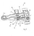
- Fig. 5 shows a further embodiment of a chain link 28, which corresponds to the chain link 8 except for the details described below.
- the chain link 28 includes a toggle 14, the first lever member 14a is pivotally connected to the pivotable roller lever 12a by means of a hinge 6 and the second lever member 14b is in communication with an actuating element 21.
- the actuator 21 actuates a pivot pin 29 to which the second lever member 14b is attached.
- the pivot mechanism 33 of the chain link 28 in turn includes a spring element, which is here, however, designed as a torsion spring, preferably as two torsion springs 30a, 30b.
- Each of the torsion springs 30a, 30b acts with its one end on the toggle lever 14 in a relative position of the two lever members 14a, 14b, which corresponds to the parallel position of the roller levers 12a, 12b.
- the other end of the torsion spring 30a, 30b is supported by a carrier. If the actuating element 21 engages with a suitable control surface 22, then the pivot pin 29 together with the toggle lever 14 is rotated against the force of the torsion spring 30a, 30b into a relative position which corresponds to the shearing position of the roller levers 12a, 12b.
- the Fig. 6 and 7 show embodiments of chain links 38 and 48, respectively, by different Holding devices are adapted to the transport of different objects G.
- the chain link 38 includes an elastic gripper 39, with which a bottle or container-shaped object G, for example, below a neck region or projecting support ring 35 can be taken.
- the gripper 39 is connected via a gripper carrier 36 with the carrier 10 of the chain link 38.
- Fig. 7 shows another chain link 48, which is equipped with a holding device in the form of a base plate 49, on the objects G are standing or lying transportable. Also, the base plate 49 is fixedly connected via a plate carrier 45 with the carrier 10 of the chain link 48.
- the attachment means for the articles may take any suitable form.
- spring elements for locking the position of the pivotable roller lever and / or as actuators for pivoting the roller lever magnets can be used.
- the roller lever can also be designed as a one-sided lever and be provided with one or a set of rollers.
- the actuator does not necessarily on one of the lever members, but can, for example, also attack the joint.
- the invention is not only applicable to conveyor chains, but can also be used in other subsidies, for example in independently movable car.
- the stops for defining the end position of the toggle lever can also on the pivoting roller lever to be appropriate.
- the lever member mounted on the chain link can also rotate in the manner of a crank in one direction.
Landscapes
- Engineering & Computer Science (AREA)
- Mechanical Engineering (AREA)
- Rollers For Roller Conveyors For Transfer (AREA)
- Chain Conveyers (AREA)
- Control Of Conveyors (AREA)
- Pusher Or Impeller Conveyors (AREA)
Claims (12)
- Dispositif de transport (1) de récipients comportant des galets de roulement (7) susceptibles de s'appuyer sur un élément de guidage (2), au moins un galet de roulement (7) étant monté sur un levier à galet (12a) susceptible de pivoter entre une première position et une seconde position à l'aide d'un mécanisme de pivotement (13, 33) et pouvant être bloqué dans une position, le mécanisme de pivotement (13, 33) comportant un levier à genouillère (14) comportant un premier et un second élément de levier (14a, 14b) reliés entre eux par l'intermédiaire d'une articulation (15), qui est relié à un élément d'actionnement (21), le second élément de levier (14b) du levier à genouillère (14) étant relié solidairement à l'élément d'actionnement (21),
caractérisé en ce que
l'élément d'actionnement (21) comporte une surface de commande qui est réalisée pour venir en prise avec une autre surface de commande (22) située à l'extérieur du dispositif de transport (1). - Dispositif de transport conforme à la revendication 1
caractérisé en ce que
les éléments de levier (14a, 14b) du levier à genouillère (14) peuvent être bloqués dans au moins une position relative. - Dispositif de transport conforme à l'une des revendications 1 et 2,
caractérisé en ce que
le levier à genouillère (14) comporte au moins un élément élastique (19, 30) de préférence précontraint permettant de bloquer les éléments de levier (14a, 14b) dans au moins une position relative. - Dispositif de transport conforme à la revendication 3,
caractérisé en ce que
l'élément élastique (30) comporte un ressort de torsion. - Dispositif de transport conforme à l'une des revendications 1 à 3,
caractérisé en ce que
le levier à genouillère (14) comporte au moins un élément élastique (19) permettant de bloquer les éléments de levier (14a, 14b) dans deux positions relatives. - Dispositif de transport conforme à la revendication 5,
caractérisé en ce que
l'un des éléments de levier (14b) est monté rotatif autour d'un axe de rotation (16) situé à distance de l'articulation (15), et l'élément élastique (19) comporte un ressort de traction qui vient en prise sur l'élément de levier (14b) au niveau d'un point d'articulation (18) qui est situé à une distance de l'axe de rotation (16) telle que lors du pivotement du levier à galet (12a) entre sa première et sa seconde position le point d'articulation (18) se déplace en passant par une position de point mort. - Dispositif de transport conforme à l'une des revendications 1 à 3,
caractérisé en ce que
le levier à genouillère (14) comporte au moins un élément magnétique permettant de bloquer les éléments de levier (14a, 14b) dans au moins une position relative. - Dispositif de transport conforme à l'une des revendications 1 à 7,
caractérisé en ce que
le levier à galet (12a, 12b) est réalisé sous la forme d'un double levier aux extrémités libres duquel est respectivement monté un galet de roulement (7). - Dispositif de transport conforme à l'une des revendications 1 à 8, réalisé sous la forme d'une chaine transporteuse comportant plusieurs éléments de chaine (8, 28, 38, 48),
caractérisé en ce que
l'élément de chaine comprend le mécanisme de pivotement (13, 33) et deux doubles leviers (12a, 12b) aux extrémités libres desquels est respectivement monté au moins un galet de roulement (7), un seul de ces doubles leviers (12a) pouvant être déplacé par pivotement par le mécanisme de pivotement (13, 33). - Dispositif de transport (1) de récipients comportant des galets de roulement (7) pouvant s'appuyer sur un élément de guidage (2), au moins un galet de roulement (7) étant monté sur un levier à galet (12a) susceptible de pivoter entre une première position et une seconde position à l'aide d'un mécanisme de pivotement (13, 33) et pouvant être bloqué dans une position, le mécanisme de pivotement (13, 33) comportant un levier à genouillère (14) comprenant un premier et un second élément de levier (14a 14b) reliés entre eux par une articulation (15), qui est relié à un élément d'actionnement (21), le second élément de levier (14b) du levier à genouillère (14) étant relié solidairement à l'élément d'actionnement (21),
caractérisé en ce que
le levier à genouillère (14) comprend au moins un élément élastique (19) pour permettre de bloquer les éléments de levier (14a, 14b) dans deux positions relatives, ou, le levier à genouillère (14) comprend au moins un élément magnétique permettant de bloquer les éléments de levier (14a, 14b) dans au moins une position relative. - Installation de transport (F) comportant un élément de guidage (2) d'un dispositif de transport,
caractérisée en ce qu'
elle comporte un dispositif de transport conforme à l'une des revendications 1 à 10. - Installation de transport conforme à la revendication 11,
caractérisée en ce qu'
à l'élément de guidage (2) du dispositif d'alimentation est associée une rampe de commande comportant une surface de commande (22) qui vient en prise avec l'élément d'actionnement (21).
Applications Claiming Priority (2)
| Application Number | Priority Date | Filing Date | Title |
|---|---|---|---|
| DE102006012148A DE102006012148A1 (de) | 2006-03-16 | 2006-03-16 | Fördermittel |
| PCT/EP2007/000485 WO2007104377A1 (fr) | 2006-03-16 | 2007-01-20 | Moyen de transport |
Publications (2)
| Publication Number | Publication Date |
|---|---|
| EP1993941A1 EP1993941A1 (fr) | 2008-11-26 |
| EP1993941B1 true EP1993941B1 (fr) | 2014-05-14 |
Family
ID=37908237
Family Applications (1)
| Application Number | Title | Priority Date | Filing Date |
|---|---|---|---|
| EP07702913.0A Not-in-force EP1993941B1 (fr) | 2006-03-16 | 2007-01-20 | Moyen de transport |
Country Status (6)
| Country | Link |
|---|---|
| US (1) | US8162129B2 (fr) |
| EP (1) | EP1993941B1 (fr) |
| JP (1) | JP4972654B2 (fr) |
| CN (1) | CN101309843B (fr) |
| DE (1) | DE102006012148A1 (fr) |
| WO (1) | WO2007104377A1 (fr) |
Families Citing this family (17)
| Publication number | Priority date | Publication date | Assignee | Title |
|---|---|---|---|---|
| JP5160789B2 (ja) | 2004-02-02 | 2013-03-13 | クロネス・アクチェンゲゼルシャフト | 物品の動的蓄積装置 |
| DE102006012148A1 (de) | 2006-03-16 | 2007-09-20 | Krones Ag | Fördermittel |
| DE102008004775A1 (de) * | 2008-01-16 | 2009-07-23 | Krones Ag | Vorrichtung zum Transportieren von Gegenständen |
| DE202008009280U1 (de) | 2008-07-10 | 2008-09-11 | Beumer Gmbh & Co. Kg | Fördervorrichtung mit entgegen der Verfahrrichtung antreibbarer Abschiebeeinrichtung |
| NL1035783C2 (nl) | 2008-08-04 | 2010-02-05 | Jan Willem Takens | Buffertransporteur voor het transporteren en bufferen van producten. |
| NL2001875C2 (nl) * | 2008-08-06 | 2010-02-09 | Specialty Conveyor Bv | Buffertransporteur voor het transporteren en bufferen van producten. |
| DE102009009044A1 (de) * | 2009-02-16 | 2010-08-26 | Beumer Gmbh & Co. Kg | Sortierförderer |
| DE102010049281B4 (de) | 2010-10-22 | 2014-05-08 | Beumer Gmbh & Co. Kg | Schwerkraftrutsche |
| DE202011106265U1 (de) | 2011-10-04 | 2011-12-23 | Beumer Gmbh & Co. Kg | Fördervorrichtung |
| EP2644538B1 (fr) * | 2012-03-27 | 2015-02-25 | Specialty Conveyor B.V. | Transporteur |
| US9856087B2 (en) | 2013-04-16 | 2018-01-02 | Illinois Tool Works Inc. | Conveyor belt and platform for conveyor belt |
| DE102013014193A1 (de) * | 2013-08-22 | 2015-02-26 | Tünkers Maschinenbau Gmbh | Förderbahn zum Fördern stückiger Bauteile |
| WO2016032999A1 (fr) * | 2014-08-25 | 2016-03-03 | Westerngeco Llc | Stockage de dispositifs capteurs |
| DE102016102474A1 (de) | 2016-02-12 | 2017-08-17 | Hauni Maschinenbau Gmbh | Vorrichtung zum Fördern eines Massenstroms stabförmiger Artikel und Verwendung derselben |
| IT201600091512A1 (it) * | 2016-09-12 | 2018-03-12 | Marchesini Group Spa | Sistema di trasporto |
| IT201800007365A1 (it) * | 2018-07-20 | 2020-01-20 | Sistema di trasporto per il trasporto di prodotti | |
| US10913610B2 (en) * | 2019-04-12 | 2021-02-09 | Sst Systems, Inc. | Conveyor roller turn |
Family Cites Families (106)
| Publication number | Priority date | Publication date | Assignee | Title |
|---|---|---|---|---|
| US1810419A (en) * | 1930-04-21 | 1931-06-16 | Jeffrey Mfg Co | Trolley conveyer |
| US2788140A (en) | 1954-09-13 | 1957-04-09 | John L Becker | Helical parking ramp |
| FR1237106A (fr) * | 1954-11-23 | 1960-07-29 | Perfectionnements aux téléfériques à mouvement continu, système monocâble (ou bicâble), avec dispositif d'accouplement automatique au câble tracteur | |
| BE639376A (fr) | 1962-11-01 | |||
| DE1802401B2 (de) | 1968-01-31 | 1971-09-09 | Gelenkkette fuer foerderanlagen mit aufeinanderfolgenden u foermig gebogenen zueinander um 90 grad gedrehten ketten gliedern | |
| GB1301843A (fr) | 1969-02-28 | 1973-01-04 | ||
| US3664487A (en) | 1969-05-23 | 1972-05-23 | Carl H Ballenger | Endless helical conveyer and belt |
| US4036356A (en) * | 1972-11-10 | 1977-07-19 | Walter Reist | Product handling equipment for an imbricated product formation |
| CH579503A5 (fr) * | 1974-07-09 | 1976-09-15 | Kernen Hans | |
| CH588647A5 (fr) | 1975-07-28 | 1977-06-15 | Ferag Ag | |
| US4018325A (en) | 1975-10-09 | 1977-04-19 | The Pillsbury Company | Automatic package accumulator |
| DE2610833A1 (de) | 1976-03-15 | 1977-09-22 | Seitz Werke Gmbh | Foerdertisch fuer gegenstaende, insbesondere fuer flaschen o.dgl. behaelter |
| DE2618905C3 (de) | 1976-04-29 | 1980-09-25 | Maschinenfabrik Alfred Schmermund Gmbh & Co, 5820 Gevelsberg | Zwischenspeicher in Form eines Übergabe-Förderers |
| SE403686B (sv) * | 1977-01-14 | 1978-08-28 | Philips Svenska Ab | Avmagnetiseringsanordning |
| US6497321B2 (en) | 2001-03-09 | 2002-12-24 | Hartness International, Inc. | Apparatus for diverting a stream of articles |
| US4269299A (en) | 1979-04-16 | 1981-05-26 | Cir-S.P.A.-Divisione Sasib | Reservoir for rod-like articles |
| US4399909A (en) | 1980-11-26 | 1983-08-23 | Roman Gorelik | Chain for a trolley conveyor system |
| IT1188972B (it) * | 1980-12-12 | 1988-01-28 | Gd Spa | Dispositivo di trasferimento per articoli a forma di barretta |
| FR2499033A1 (fr) | 1981-02-03 | 1982-08-06 | Nantaise Biscuiterie | Procede et dispositif pour regulariser le transfert de produits solides identiques |
| US4413724A (en) | 1981-05-18 | 1983-11-08 | Mapatent, N.V. | Horizontal accumulator |
| US4513858A (en) | 1981-05-18 | 1985-04-30 | Mapatent, N.V. | Horizontal accumulator |
| FR2524436B1 (fr) | 1982-04-02 | 1985-09-27 | Nantaise Biscuiterie | Dispositif regulateur de transfert de produits solides identiques entre des machines amont et aval de vitesses differentes |
| IT1156583B (it) | 1982-04-13 | 1987-02-04 | Gd Spa | Apparecchiatura per il trasferimento di prodotti singoli o condizionati in gruppi da una prima ad una seconda macchina operatrice |
| US4468277A (en) | 1983-07-05 | 1984-08-28 | Owens-Illinois, Inc. | Fixed jaw means for holding and rotating containers traveling around a turret periphery |
| GB2143788B (en) | 1983-07-20 | 1986-08-28 | British American Tobacco Co | Rod-like article conveying and storage system |
| JPS61197376A (ja) * | 1985-02-23 | 1986-09-01 | Toyoda Autom Loom Works Ltd | ボビン搬送体のボビンピツチ変更装置 |
| JPS61197376U (fr) | 1985-05-30 | 1986-12-09 | ||
| SU1458295A1 (ru) | 1986-10-01 | 1989-02-15 | Издательство "Известия" Советов Народных Депутатов Ссср | Узел соединени обойм пространственного конвейера |
| US4838410A (en) | 1987-06-11 | 1989-06-13 | Refac International, Limited | Chain and chain track for rotating conveyor bucket |
| NL8702159A (nl) * | 1987-09-10 | 1989-04-03 | Johannes Gerhardus Christianus | Sorteerinrichting met langs een transportbaan beweegbare transportorganen voor de te sorteren voorwerpen. |
| RU2027648C1 (ru) | 1988-10-20 | 1995-01-27 | Радуцкий Григорий Аврамович | Пространственный конвейер |
| DE8900172U1 (de) * | 1989-01-09 | 1990-05-10 | Veit Transpo GmbH, 8910 Landsberg | Hängefördereinrichtung |
| US4989718A (en) | 1989-08-23 | 1991-02-05 | Hartness International, Inc. | Surge control method and apparatus |
| US5022609A (en) * | 1990-01-10 | 1991-06-11 | Lockheed Corporation | Landing gear |
| US5076422A (en) | 1990-08-29 | 1991-12-31 | Tekno Incorporated | Side-flexing chain with wheels |
| DE4125573A1 (de) * | 1990-11-13 | 1992-05-14 | Hermann Kronseder | Vorrichtung zum ein- oder auspacken von behaeltern |
| FR2674512B1 (fr) | 1991-03-27 | 1995-10-27 | Sgie Ind Sa | Convoyeur avec accumulation. |
| US5253742A (en) * | 1992-05-07 | 1993-10-19 | Dooley Richard Anthony | Conveyor hangers with articulated linkages |
| US5191959A (en) | 1992-06-10 | 1993-03-09 | Alvey Inc. | Sorting conveyor with vertical switching system |
| DE4224609A1 (de) | 1992-07-25 | 1994-01-27 | Hauni Werke Koerber & Co Kg | Fördervorrichtung für Zigaretten |
| US5413213A (en) | 1992-07-25 | 1995-05-09 | Korber Ag | Apparatus for transporting mass flows of articles |
| DE4324120A1 (de) | 1993-07-19 | 1995-01-26 | Hauni Werke Koerber & Co Kg | Förderkette |
| DE4332342A1 (de) * | 1993-09-23 | 1995-03-30 | Kronseder Maschf Krones | Verfahren und Packmaschine zum Entnehmen von Gefäßen aus Transportbehältern |
| US5645159A (en) | 1994-03-30 | 1997-07-08 | Lauener Engineering, Ltd. | Method and apparatus for continuously casting metal |
| US6325204B1 (en) | 1994-03-30 | 2001-12-04 | Nichols Aluminum-Golden, Inc. | Method and drive apparatus for continuously casting metal in a continuous block caster |
| CH689773A5 (de) | 1995-02-16 | 1999-10-29 | Ferag Ag | Vorrichtung zum Vergleichmaessigen des Abstandes zwischen aufeinanderfolgenden flaechigen Produkten. |
| FR2731176B1 (fr) | 1995-03-02 | 1997-04-30 | Sidel Sa | Installation de fabrication de recipients par soufflage de preformes en matiere plastique |
| FR2732002B1 (fr) | 1995-03-23 | 1997-06-06 | Sidel Sa | Installation d'embouteillage en ligne |
| US5620084A (en) | 1995-03-30 | 1997-04-15 | Jervis B. Webb Company | Chain propelled belt conveyor |
| CH690646A5 (de) | 1995-05-09 | 2000-11-30 | Ferag Ag | Vorrichtung zum Fördern von Gegenständen. |
| US6105338A (en) * | 1995-11-02 | 2000-08-22 | R.A. Jones & Co. Inc. | Case packer |
| FR2745804B1 (fr) | 1996-03-08 | 1998-04-17 | Schneider Electric Sa | Dispositif de transfert et de stockage temporaire |
| EP0912426B1 (fr) * | 1996-05-13 | 2000-08-09 | IPT Weinfelden AG | Procede de transport suspendu de recipients et dispositif approprie pour mettre ledit procede en oeuvre |
| IT1289906B1 (it) | 1997-01-16 | 1998-10-19 | S B R S R L | Pinza di afferraggio di contenitori quali in particolare bottiglie |
| FR2766803A1 (fr) | 1997-07-31 | 1999-02-05 | Diaz Jose Arriaza | Accumulateur |
| US6260688B1 (en) | 1999-01-22 | 2001-07-17 | Hartness International | Apparatus for controlling the flow of articles |
| US6152291A (en) | 1998-03-09 | 2000-11-28 | Hartness International | Apparatus for controlling the flow of articles |
| DE19816239A1 (de) | 1998-04-11 | 1999-10-14 | Krones Ag | Vorrichtung zum Einbringen und/oder Ausbringen von Behältern in bzw. aus einem Behandlungsraum |
| DE19824846A1 (de) | 1998-06-04 | 1999-12-09 | Khs Masch & Anlagenbau Ag | Anlage zum Abfüllen von flüssigem Füllgut |
| US6168004B1 (en) | 1998-11-05 | 2001-01-02 | Kalish Canada, Inc. | Container distribution apparatus |
| US6209716B1 (en) | 1998-11-05 | 2001-04-03 | The Laitram Corporation | Knuckle drive link conveyor belt systems with removable load conveying surface members |
| US6119848A (en) | 1999-01-22 | 2000-09-19 | Hartness International | Conveyor motor drive unit and conveyor system |
| DE19922873A1 (de) | 1999-05-19 | 2000-11-23 | Krones Ag | Vorrichtung zum Einbringen und/oder Ausbringen von Behältern |
| DE19928325A1 (de) | 1999-06-21 | 2000-12-28 | Krones Ag | Abfüllvorrichtung für Flaschen |
| US6241074B1 (en) | 1999-07-30 | 2001-06-05 | Hartness International, Inc. | Guide device for transferring articles between conveyors |
| US6182812B1 (en) | 1999-07-30 | 2001-02-06 | Hartness International | Device for transferring articles between oppositely running conveyors |
| DE29913237U1 (de) | 1999-08-04 | 2000-12-21 | Autefa Maschinenfabrik GmbH, 86316 Friedberg | Pufferanordnung für Flaschen in einer Flaschenbehandlungsanlage |
| FR2800361B1 (fr) | 1999-10-29 | 2001-12-07 | Serac Group | Installation de transfert de recipients comportant un organe de deviation |
| US6230874B1 (en) | 1999-12-07 | 2001-05-15 | Hartness International | Apparatus for controlling the flow of articles |
| FR2802191B1 (fr) | 1999-12-13 | 2002-03-01 | Sidel Sa | Dispositif de convoyage d'entites discretes comportant un bras de transfert perfectionne et installation de soufflage de recipients munie d'un tel dispositif |
| FR2807413B1 (fr) | 2000-04-07 | 2002-08-02 | Sogem Agro | Dispositif accumulateur en u, du type a bandes sans fin |
| US6334528B1 (en) | 2000-06-16 | 2002-01-01 | The Laitram Corporation | Variable-width spacer |
| US6394260B1 (en) | 2000-07-17 | 2002-05-28 | Pflow Industries, Inc. | Conveyor system including roller-guided carriage assemblies |
| US6698581B2 (en) | 2000-08-29 | 2004-03-02 | Hartness International | Article guide for an apparatus for controlling the flow of articles |
| US6523669B1 (en) | 2000-08-29 | 2003-02-25 | Hartness International, Inc. | Article guide for an apparatus for controlling the flow of articles |
| US6612420B1 (en) | 2000-10-17 | 2003-09-02 | Hartness International, Inc. | Device for transferring articles between oppositely running conveyors |
| ITBO20000654A1 (it) * | 2000-11-14 | 2002-05-14 | Sichera Di Sichera Gianni | Macchina per il confezionamento di articoli, in particolare cd, dvd esimili, in relativi contenitori |
| FR2819499B1 (fr) | 2001-01-15 | 2003-03-28 | Realisations Electr Et Mecaniq | Procede et dispositif de stockage en lignes de paquets de produits plats tels que, notamment, changes ou serviettes periodiques |
| JP4662100B2 (ja) | 2001-04-04 | 2011-03-30 | 東洋自動機株式会社 | 袋詰め包装機における袋移送装置 |
| US6591963B2 (en) | 2001-06-26 | 2003-07-15 | Sig Pack Systems Ag | Storage apparatus |
| ITBO20010424A1 (it) | 2001-07-05 | 2003-01-05 | Gd Spa | Magazzino a capacita' variabile per oggetti |
| US6601697B2 (en) | 2001-07-25 | 2003-08-05 | Hartness International | Sloped surface conveyor belt |
| US6533103B2 (en) | 2001-07-27 | 2003-03-18 | Hartness International | Transfer device for use between two conveyors |
| ATE311337T1 (de) | 2001-09-20 | 2005-12-15 | Sig Simonazzi Spa | Vorrichtung zum vorübergehend zwischenspeichern von gegenständen in einer verarbeitungslinie |
| CA2364216A1 (fr) | 2001-12-07 | 2003-06-07 | Harry T. Pappas | Transporteur a accumulation dynamique |
| FR2838712B1 (fr) | 2002-04-22 | 2004-06-25 | Serac Group | Dispositif de prehension de recipients a commande excentrique |
| ITBO20020389A1 (it) | 2002-06-18 | 2003-12-18 | Gd Spa | Unita a magazzino per prodotti di forma sostanzialmente parallelepipeda |
| US6999847B2 (en) | 2002-07-26 | 2006-02-14 | Unelab Llc | Specimen carrier transfer apparatus for a conveyor track |
| JP4285727B2 (ja) | 2002-11-08 | 2009-06-24 | 株式会社フロンティア | ブロー成形装置の移送機構 |
| DE10301178B4 (de) | 2003-01-15 | 2006-07-13 | Khs Kisters Maschinenbau Gmbh | Vorrichtung zum Ausrichten und Verteilen |
| ITMI20030194A1 (it) | 2003-02-05 | 2004-08-06 | Smi Spa | Stella con bracci a passo variabile per macchine rotative |
| GB2399797B (en) | 2003-03-25 | 2006-04-26 | Flexlink Components Ab | A variable capacity store for elongated articles |
| US7264113B2 (en) | 2003-11-13 | 2007-09-04 | Hartness International, Inc. | Pivotable conveyor and link |
| US7278531B2 (en) | 2004-06-29 | 2007-10-09 | Hartness International, Inc. | Flexible conveyor and connection elements |
| DE102004053663A1 (de) | 2004-02-02 | 2005-08-18 | Krones Ag | Vorrichtung zum dynamischen Speichern von Gegenständen |
| JP5160789B2 (ja) * | 2004-02-02 | 2013-03-13 | クロネス・アクチェンゲゼルシャフト | 物品の動的蓄積装置 |
| US7032742B2 (en) | 2004-04-02 | 2006-04-25 | Hartness International, Inc. | Differential drive spiral accumulator apparatus |
| US7299832B2 (en) | 2004-06-29 | 2007-11-27 | Hartness International, Inc. | Rotary filling machine and related components, and related method |
| US7331156B2 (en) | 2004-06-29 | 2008-02-19 | Hartness International, Inc. | System for securely conveying articles and related components |
| FR2881677B1 (fr) | 2005-02-08 | 2007-04-27 | Sidel Sas | Dispositif rotatif de transfert de recipients |
| EP1693322A1 (fr) | 2005-02-21 | 2006-08-23 | Ferag AG | Système de transport comprenant des éléments avec galets de roulement pour le convoyage le long d'un guide et procédé de fabrication des galets de roulement |
| DE202005013552U1 (de) * | 2005-08-27 | 2005-11-03 | Krones Ag | Dynamischer Speicher für Gegenstände |
| ATE461891T1 (de) | 2006-03-08 | 2010-04-15 | Ferag Ag | Förderkette aus über gelenklager miteinander verbundenen kettengliedern und verfahren zur montage der kettenglieder |
| DE202006003690U1 (de) | 2006-03-09 | 2006-06-14 | Khs Ag | Förderweiche |
| DE102006012148A1 (de) | 2006-03-16 | 2007-09-20 | Krones Ag | Fördermittel |
| JP5211517B2 (ja) | 2007-03-15 | 2013-06-12 | 澁谷工業株式会社 | 物品搬送装置 |
-
2006
- 2006-03-16 DE DE102006012148A patent/DE102006012148A1/de not_active Withdrawn
-
2007
- 2007-01-20 WO PCT/EP2007/000485 patent/WO2007104377A1/fr not_active Ceased
- 2007-01-20 CN CN2007800000796A patent/CN101309843B/zh not_active Expired - Fee Related
- 2007-01-20 JP JP2008558658A patent/JP4972654B2/ja not_active Expired - Fee Related
- 2007-01-20 US US12/063,102 patent/US8162129B2/en not_active Expired - Fee Related
- 2007-01-20 EP EP07702913.0A patent/EP1993941B1/fr not_active Not-in-force
Also Published As
| Publication number | Publication date |
|---|---|
| JP2009529475A (ja) | 2009-08-20 |
| CN101309843A (zh) | 2008-11-19 |
| WO2007104377A1 (fr) | 2007-09-20 |
| DE102006012148A1 (de) | 2007-09-20 |
| US20100314223A1 (en) | 2010-12-16 |
| EP1993941A1 (fr) | 2008-11-26 |
| US8162129B2 (en) | 2012-04-24 |
| CN101309843B (zh) | 2012-06-20 |
| JP4972654B2 (ja) | 2012-07-11 |
Similar Documents
| Publication | Publication Date | Title |
|---|---|---|
| EP1993941B1 (fr) | Moyen de transport | |
| EP1711420B1 (fr) | Dispositif de stockage dynamique d'objets | |
| EP1474348A1 (fr) | Dispositif de transport | |
| EP2380832A1 (fr) | Dispositif pour le stockage dynamique d'objets | |
| CH677652A5 (fr) | ||
| EP1986940A1 (fr) | Dispositif pour accumuker des objets | |
| EP2314529B1 (fr) | Unité de transport dotée de chaînes à petits rouleaux de retenue | |
| DE102008037865A1 (de) | Transportvorrichtung | |
| EP0456978A1 (fr) | Pince pour le transport de produits, en particulier de produits plats | |
| DE102004007590B4 (de) | Dynamischer Puffer | |
| WO2008083816A1 (fr) | Dispositif pour regrouper des récipients, comme des petits conteneurs ou analogues | |
| DE102016113376A1 (de) | Transportvorrichtung | |
| DE1492475B2 (de) | Foerdervorrichtung fuer eine anlage zum sterilisieren und pasteurisieren von in behaeltern verpackten waren | |
| EP2256070B1 (fr) | Dispositif de convoyeur de bande | |
| DE102016121253A1 (de) | Vorrichtung zum Transportieren von Objekten und insbesondere von Verpackungen, Getränkekästen und dergleichen | |
| DE69313490T2 (de) | Greiferförderer | |
| EP0594090B1 (fr) | Dispositif de positionnement d'objets | |
| DE3541364C2 (de) | Tragglied für Gliederbandförderer | |
| DE3124600A1 (de) | Stabilisierungseinrichtung fuer die gegenstaende tragenden glieder in einem transfersystem | |
| DE3936647C1 (fr) | ||
| EP3044132A1 (fr) | Roue transporteuse et système de transport | |
| DE29519805U1 (de) | Transfereinrichtung für Fördergut | |
| EP3064454B1 (fr) | Chaine de transport d'articles et systeme de transport dote de ladite chaine de transport | |
| AT409116B (de) | Anlage für den transport von schüttgut | |
| DE102024124039B3 (de) | Rollenbahn zum Fördern von Fördergut sowie Verfahren zum Betrieb der Rollenbahn |
Legal Events
| Date | Code | Title | Description |
|---|---|---|---|
| PUAI | Public reference made under article 153(3) epc to a published international application that has entered the european phase |
Free format text: ORIGINAL CODE: 0009012 |
|
| 17P | Request for examination filed |
Effective date: 20070702 |
|
| AK | Designated contracting states |
Kind code of ref document: A1 Designated state(s): AT BE BG CH CY CZ DE DK EE ES FI FR GB GR HU IE IS IT LI LT LU LV MC NL PL PT RO SE SI SK TR |
|
| 17Q | First examination report despatched |
Effective date: 20081121 |
|
| DAX | Request for extension of the european patent (deleted) | ||
| RIC1 | Information provided on ipc code assigned before grant |
Ipc: B65G 17/20 20060101AFI20131127BHEP Ipc: B65G 47/51 20060101ALI20131127BHEP Ipc: B65G 21/18 20060101ALI20131127BHEP |
|
| GRAP | Despatch of communication of intention to grant a patent |
Free format text: ORIGINAL CODE: EPIDOSNIGR1 |
|
| INTG | Intention to grant announced |
Effective date: 20140122 |
|
| GRAS | Grant fee paid |
Free format text: ORIGINAL CODE: EPIDOSNIGR3 |
|
| GRAA | (expected) grant |
Free format text: ORIGINAL CODE: 0009210 |
|
| AK | Designated contracting states |
Kind code of ref document: B1 Designated state(s): AT BE BG CH CY CZ DE DK EE ES FI FR GB GR HU IE IS IT LI LT LU LV MC NL PL PT RO SE SI SK TR |
|
| REG | Reference to a national code |
Ref country code: GB Ref legal event code: FG4D Free format text: NOT ENGLISH |
|
| REG | Reference to a national code |
Ref country code: AT Ref legal event code: REF Ref document number: 668131 Country of ref document: AT Kind code of ref document: T Effective date: 20140615 |
|
| REG | Reference to a national code |
Ref country code: IE Ref legal event code: FG4D Free format text: LANGUAGE OF EP DOCUMENT: GERMAN |
|
| REG | Reference to a national code |
Ref country code: DE Ref legal event code: R096 Ref document number: 502007013116 Country of ref document: DE Effective date: 20140626 |
|
| REG | Reference to a national code |
Ref country code: NL Ref legal event code: VDEP Effective date: 20140514 |
|
| REG | Reference to a national code |
Ref country code: LT Ref legal event code: MG4D |
|
| PG25 | Lapsed in a contracting state [announced via postgrant information from national office to epo] |
Ref country code: LT Free format text: LAPSE BECAUSE OF FAILURE TO SUBMIT A TRANSLATION OF THE DESCRIPTION OR TO PAY THE FEE WITHIN THE PRESCRIBED TIME-LIMIT Effective date: 20140514 Ref country code: IS Free format text: LAPSE BECAUSE OF FAILURE TO SUBMIT A TRANSLATION OF THE DESCRIPTION OR TO PAY THE FEE WITHIN THE PRESCRIBED TIME-LIMIT Effective date: 20140914 Ref country code: FI Free format text: LAPSE BECAUSE OF FAILURE TO SUBMIT A TRANSLATION OF THE DESCRIPTION OR TO PAY THE FEE WITHIN THE PRESCRIBED TIME-LIMIT Effective date: 20140514 Ref country code: GR Free format text: LAPSE BECAUSE OF FAILURE TO SUBMIT A TRANSLATION OF THE DESCRIPTION OR TO PAY THE FEE WITHIN THE PRESCRIBED TIME-LIMIT Effective date: 20140815 Ref country code: CY Free format text: LAPSE BECAUSE OF FAILURE TO SUBMIT A TRANSLATION OF THE DESCRIPTION OR TO PAY THE FEE WITHIN THE PRESCRIBED TIME-LIMIT Effective date: 20140514 |
|
| PG25 | Lapsed in a contracting state [announced via postgrant information from national office to epo] |
Ref country code: PL Free format text: LAPSE BECAUSE OF FAILURE TO SUBMIT A TRANSLATION OF THE DESCRIPTION OR TO PAY THE FEE WITHIN THE PRESCRIBED TIME-LIMIT Effective date: 20140514 Ref country code: SE Free format text: LAPSE BECAUSE OF FAILURE TO SUBMIT A TRANSLATION OF THE DESCRIPTION OR TO PAY THE FEE WITHIN THE PRESCRIBED TIME-LIMIT Effective date: 20140514 Ref country code: LV Free format text: LAPSE BECAUSE OF FAILURE TO SUBMIT A TRANSLATION OF THE DESCRIPTION OR TO PAY THE FEE WITHIN THE PRESCRIBED TIME-LIMIT Effective date: 20140514 Ref country code: ES Free format text: LAPSE BECAUSE OF FAILURE TO SUBMIT A TRANSLATION OF THE DESCRIPTION OR TO PAY THE FEE WITHIN THE PRESCRIBED TIME-LIMIT Effective date: 20140514 |
|
| PG25 | Lapsed in a contracting state [announced via postgrant information from national office to epo] |
Ref country code: PT Free format text: LAPSE BECAUSE OF FAILURE TO SUBMIT A TRANSLATION OF THE DESCRIPTION OR TO PAY THE FEE WITHIN THE PRESCRIBED TIME-LIMIT Effective date: 20140915 |
|
| PG25 | Lapsed in a contracting state [announced via postgrant information from national office to epo] |
Ref country code: EE Free format text: LAPSE BECAUSE OF FAILURE TO SUBMIT A TRANSLATION OF THE DESCRIPTION OR TO PAY THE FEE WITHIN THE PRESCRIBED TIME-LIMIT Effective date: 20140514 Ref country code: RO Free format text: LAPSE BECAUSE OF FAILURE TO SUBMIT A TRANSLATION OF THE DESCRIPTION OR TO PAY THE FEE WITHIN THE PRESCRIBED TIME-LIMIT Effective date: 20140514 Ref country code: CZ Free format text: LAPSE BECAUSE OF FAILURE TO SUBMIT A TRANSLATION OF THE DESCRIPTION OR TO PAY THE FEE WITHIN THE PRESCRIBED TIME-LIMIT Effective date: 20140514 Ref country code: DK Free format text: LAPSE BECAUSE OF FAILURE TO SUBMIT A TRANSLATION OF THE DESCRIPTION OR TO PAY THE FEE WITHIN THE PRESCRIBED TIME-LIMIT Effective date: 20140514 Ref country code: SK Free format text: LAPSE BECAUSE OF FAILURE TO SUBMIT A TRANSLATION OF THE DESCRIPTION OR TO PAY THE FEE WITHIN THE PRESCRIBED TIME-LIMIT Effective date: 20140514 |
|
| REG | Reference to a national code |
Ref country code: DE Ref legal event code: R097 Ref document number: 502007013116 Country of ref document: DE |
|
| PG25 | Lapsed in a contracting state [announced via postgrant information from national office to epo] |
Ref country code: NL Free format text: LAPSE BECAUSE OF FAILURE TO SUBMIT A TRANSLATION OF THE DESCRIPTION OR TO PAY THE FEE WITHIN THE PRESCRIBED TIME-LIMIT Effective date: 20140514 |
|
| PLBE | No opposition filed within time limit |
Free format text: ORIGINAL CODE: 0009261 |
|
| STAA | Information on the status of an ep patent application or granted ep patent |
Free format text: STATUS: NO OPPOSITION FILED WITHIN TIME LIMIT |
|
| 26N | No opposition filed |
Effective date: 20150217 |
|
| REG | Reference to a national code |
Ref country code: DE Ref legal event code: R097 Ref document number: 502007013116 Country of ref document: DE Effective date: 20150217 |
|
| PG25 | Lapsed in a contracting state [announced via postgrant information from national office to epo] |
Ref country code: BE Free format text: LAPSE BECAUSE OF NON-PAYMENT OF DUE FEES Effective date: 20150131 |
|
| PG25 | Lapsed in a contracting state [announced via postgrant information from national office to epo] |
Ref country code: SI Free format text: LAPSE BECAUSE OF FAILURE TO SUBMIT A TRANSLATION OF THE DESCRIPTION OR TO PAY THE FEE WITHIN THE PRESCRIBED TIME-LIMIT Effective date: 20140514 |
|
| REG | Reference to a national code |
Ref country code: CH Ref legal event code: PL |
|
| PG25 | Lapsed in a contracting state [announced via postgrant information from national office to epo] |
Ref country code: LU Free format text: LAPSE BECAUSE OF FAILURE TO SUBMIT A TRANSLATION OF THE DESCRIPTION OR TO PAY THE FEE WITHIN THE PRESCRIBED TIME-LIMIT Effective date: 20150120 |
|
| GBPC | Gb: european patent ceased through non-payment of renewal fee |
Effective date: 20150120 |
|
| PG25 | Lapsed in a contracting state [announced via postgrant information from national office to epo] |
Ref country code: MC Free format text: LAPSE BECAUSE OF FAILURE TO SUBMIT A TRANSLATION OF THE DESCRIPTION OR TO PAY THE FEE WITHIN THE PRESCRIBED TIME-LIMIT Effective date: 20140514 |
|
| PG25 | Lapsed in a contracting state [announced via postgrant information from national office to epo] |
Ref country code: CH Free format text: LAPSE BECAUSE OF NON-PAYMENT OF DUE FEES Effective date: 20150131 Ref country code: LI Free format text: LAPSE BECAUSE OF NON-PAYMENT OF DUE FEES Effective date: 20150131 Ref country code: GB Free format text: LAPSE BECAUSE OF NON-PAYMENT OF DUE FEES Effective date: 20150120 |
|
| REG | Reference to a national code |
Ref country code: IE Ref legal event code: MM4A |
|
| REG | Reference to a national code |
Ref country code: FR Ref legal event code: PLFP Year of fee payment: 10 |
|
| PG25 | Lapsed in a contracting state [announced via postgrant information from national office to epo] |
Ref country code: IE Free format text: LAPSE BECAUSE OF NON-PAYMENT OF DUE FEES Effective date: 20150120 |
|
| REG | Reference to a national code |
Ref country code: AT Ref legal event code: MM01 Ref document number: 668131 Country of ref document: AT Kind code of ref document: T Effective date: 20150120 |
|
| PG25 | Lapsed in a contracting state [announced via postgrant information from national office to epo] |
Ref country code: AT Free format text: LAPSE BECAUSE OF NON-PAYMENT OF DUE FEES Effective date: 20150120 |
|
| REG | Reference to a national code |
Ref country code: FR Ref legal event code: PLFP Year of fee payment: 11 |
|
| PGFP | Annual fee paid to national office [announced via postgrant information from national office to epo] |
Ref country code: FR Payment date: 20161215 Year of fee payment: 11 |
|
| PGFP | Annual fee paid to national office [announced via postgrant information from national office to epo] |
Ref country code: DE Payment date: 20170117 Year of fee payment: 11 |
|
| PG25 | Lapsed in a contracting state [announced via postgrant information from national office to epo] |
Ref country code: HU Free format text: LAPSE BECAUSE OF FAILURE TO SUBMIT A TRANSLATION OF THE DESCRIPTION OR TO PAY THE FEE WITHIN THE PRESCRIBED TIME-LIMIT; INVALID AB INITIO Effective date: 20070120 Ref country code: BG Free format text: LAPSE BECAUSE OF FAILURE TO SUBMIT A TRANSLATION OF THE DESCRIPTION OR TO PAY THE FEE WITHIN THE PRESCRIBED TIME-LIMIT Effective date: 20140514 |
|
| PGFP | Annual fee paid to national office [announced via postgrant information from national office to epo] |
Ref country code: IT Payment date: 20170123 Year of fee payment: 11 |
|
| PG25 | Lapsed in a contracting state [announced via postgrant information from national office to epo] |
Ref country code: TR Free format text: LAPSE BECAUSE OF FAILURE TO SUBMIT A TRANSLATION OF THE DESCRIPTION OR TO PAY THE FEE WITHIN THE PRESCRIBED TIME-LIMIT Effective date: 20140514 |
|
| REG | Reference to a national code |
Ref country code: DE Ref legal event code: R119 Ref document number: 502007013116 Country of ref document: DE |
|
| PG25 | Lapsed in a contracting state [announced via postgrant information from national office to epo] |
Ref country code: FR Free format text: LAPSE BECAUSE OF NON-PAYMENT OF DUE FEES Effective date: 20180131 Ref country code: DE Free format text: LAPSE BECAUSE OF NON-PAYMENT OF DUE FEES Effective date: 20180801 |
|
| REG | Reference to a national code |
Ref country code: FR Ref legal event code: ST Effective date: 20180928 |
|
| PG25 | Lapsed in a contracting state [announced via postgrant information from national office to epo] |
Ref country code: IT Free format text: LAPSE BECAUSE OF NON-PAYMENT OF DUE FEES Effective date: 20180120 |