EP2380832A1 - Dispositif pour le stockage dynamique d'objets - Google Patents
Dispositif pour le stockage dynamique d'objets Download PDFInfo
- Publication number
- EP2380832A1 EP2380832A1 EP11174839A EP11174839A EP2380832A1 EP 2380832 A1 EP2380832 A1 EP 2380832A1 EP 11174839 A EP11174839 A EP 11174839A EP 11174839 A EP11174839 A EP 11174839A EP 2380832 A1 EP2380832 A1 EP 2380832A1
- Authority
- EP
- European Patent Office
- Prior art keywords
- guide
- roller
- conveyor
- chain
- carriage
- Prior art date
- Legal status (The legal status is an assumption and is not a legal conclusion. Google has not performed a legal analysis and makes no representation as to the accuracy of the status listed.)
- Withdrawn
Links
- 238000003860 storage Methods 0.000 title claims abstract description 13
- 230000006835 compression Effects 0.000 claims description 2
- 238000007906 compression Methods 0.000 claims description 2
- 230000002441 reversible effect Effects 0.000 claims 1
- 238000002372 labelling Methods 0.000 description 10
- 238000013461 design Methods 0.000 description 8
- 238000011049 filling Methods 0.000 description 7
- 238000004806 packaging method and process Methods 0.000 description 6
- 238000000071 blow moulding Methods 0.000 description 5
- 230000007704 transition Effects 0.000 description 5
- 230000006870 function Effects 0.000 description 4
- 210000003813 thumb Anatomy 0.000 description 4
- 238000009826 distribution Methods 0.000 description 3
- 230000003139 buffering effect Effects 0.000 description 2
- 230000000694 effects Effects 0.000 description 2
- 230000006386 memory function Effects 0.000 description 2
- 125000006850 spacer group Chemical group 0.000 description 2
- 238000012546 transfer Methods 0.000 description 2
- 235000013361 beverage Nutrition 0.000 description 1
- 230000008859 change Effects 0.000 description 1
- 238000004140 cleaning Methods 0.000 description 1
- 238000010276 construction Methods 0.000 description 1
- 238000001816 cooling Methods 0.000 description 1
- 230000008878 coupling Effects 0.000 description 1
- 238000010168 coupling process Methods 0.000 description 1
- 238000005859 coupling reaction Methods 0.000 description 1
- 238000011161 development Methods 0.000 description 1
- 230000018109 developmental process Effects 0.000 description 1
- 239000011521 glass Substances 0.000 description 1
- 230000001771 impaired effect Effects 0.000 description 1
- 230000006872 improvement Effects 0.000 description 1
- 238000007689 inspection Methods 0.000 description 1
- 238000009434 installation Methods 0.000 description 1
- 238000004519 manufacturing process Methods 0.000 description 1
- 239000002184 metal Substances 0.000 description 1
- 238000000034 method Methods 0.000 description 1
- 238000012856 packing Methods 0.000 description 1
- 230000008569 process Effects 0.000 description 1
- 230000004044 response Effects 0.000 description 1
- 238000005096 rolling process Methods 0.000 description 1
- 238000010079 rubber tapping Methods 0.000 description 1
- 238000007789 sealing Methods 0.000 description 1
- 230000007480 spreading Effects 0.000 description 1
- 238000003892 spreading Methods 0.000 description 1
- 230000006641 stabilisation Effects 0.000 description 1
- 238000011105 stabilization Methods 0.000 description 1
- 230000008719 thickening Effects 0.000 description 1
- 238000011144 upstream manufacturing Methods 0.000 description 1
- 238000003466 welding Methods 0.000 description 1
Images











Classifications
-
- B—PERFORMING OPERATIONS; TRANSPORTING
- B65—CONVEYING; PACKING; STORING; HANDLING THIN OR FILAMENTARY MATERIAL
- B65G—TRANSPORT OR STORAGE DEVICES, e.g. CONVEYORS FOR LOADING OR TIPPING, SHOP CONVEYOR SYSTEMS OR PNEUMATIC TUBE CONVEYORS
- B65G47/00—Article or material-handling devices associated with conveyors; Methods employing such devices
- B65G47/34—Devices for discharging articles or materials from conveyor
- B65G47/46—Devices for discharging articles or materials from conveyor and distributing, e.g. automatically, to desired points
- B65G47/51—Devices for discharging articles or materials from conveyor and distributing, e.g. automatically, to desired points according to unprogrammed signals, e.g. influenced by supply situation at destination
- B65G47/5104—Devices for discharging articles or materials from conveyor and distributing, e.g. automatically, to desired points according to unprogrammed signals, e.g. influenced by supply situation at destination for articles
- B65G47/5109—Devices for discharging articles or materials from conveyor and distributing, e.g. automatically, to desired points according to unprogrammed signals, e.g. influenced by supply situation at destination for articles first In - First Out systems: FIFO
- B65G47/5113—Devices for discharging articles or materials from conveyor and distributing, e.g. automatically, to desired points according to unprogrammed signals, e.g. influenced by supply situation at destination for articles first In - First Out systems: FIFO using endless conveyors
- B65G47/5118—Devices for discharging articles or materials from conveyor and distributing, e.g. automatically, to desired points according to unprogrammed signals, e.g. influenced by supply situation at destination for articles first In - First Out systems: FIFO using endless conveyors with variable accumulation capacity
- B65G47/5122—Devices for discharging articles or materials from conveyor and distributing, e.g. automatically, to desired points according to unprogrammed signals, e.g. influenced by supply situation at destination for articles first In - First Out systems: FIFO using endless conveyors with variable accumulation capacity by displacement of the conveyor-guiding means, e.g. of the loose pulley-type
-
- B—PERFORMING OPERATIONS; TRANSPORTING
- B65—CONVEYING; PACKING; STORING; HANDLING THIN OR FILAMENTARY MATERIAL
- B65G—TRANSPORT OR STORAGE DEVICES, e.g. CONVEYORS FOR LOADING OR TIPPING, SHOP CONVEYOR SYSTEMS OR PNEUMATIC TUBE CONVEYORS
- B65G17/00—Conveyors having an endless traction element, e.g. a chain, transmitting movement to a continuous or substantially-continuous load-carrying surface or to a series of individual load-carriers; Endless-chain conveyors in which the chains form the load-carrying surface
- B65G17/30—Details; Auxiliary devices
- B65G17/38—Chains or like traction elements; Connections between traction elements and load-carriers
- B65G17/385—Chains or like traction elements; Connections between traction elements and load-carriers adapted to follow three-dimensionally curved paths
-
- B—PERFORMING OPERATIONS; TRANSPORTING
- B65—CONVEYING; PACKING; STORING; HANDLING THIN OR FILAMENTARY MATERIAL
- B65G—TRANSPORT OR STORAGE DEVICES, e.g. CONVEYORS FOR LOADING OR TIPPING, SHOP CONVEYOR SYSTEMS OR PNEUMATIC TUBE CONVEYORS
- B65G21/00—Supporting or protective framework or housings for endless load-carriers or traction elements of belt or chain conveyors
- B65G21/16—Supporting or protective framework or housings for endless load-carriers or traction elements of belt or chain conveyors for conveyors having endless load-carriers movable in curved paths
- B65G21/18—Supporting or protective framework or housings for endless load-carriers or traction elements of belt or chain conveyors for conveyors having endless load-carriers movable in curved paths in three-dimensionally curved paths
-
- B—PERFORMING OPERATIONS; TRANSPORTING
- B65—CONVEYING; PACKING; STORING; HANDLING THIN OR FILAMENTARY MATERIAL
- B65G—TRANSPORT OR STORAGE DEVICES, e.g. CONVEYORS FOR LOADING OR TIPPING, SHOP CONVEYOR SYSTEMS OR PNEUMATIC TUBE CONVEYORS
- B65G2201/00—Indexing codes relating to handling devices, e.g. conveyors, characterised by the type of product or load being conveyed or handled
- B65G2201/02—Articles
- B65G2201/0235—Containers
- B65G2201/0244—Bottles
- B65G2201/0247—Suspended bottles
-
- B—PERFORMING OPERATIONS; TRANSPORTING
- B65—CONVEYING; PACKING; STORING; HANDLING THIN OR FILAMENTARY MATERIAL
- B65G—TRANSPORT OR STORAGE DEVICES, e.g. CONVEYORS FOR LOADING OR TIPPING, SHOP CONVEYOR SYSTEMS OR PNEUMATIC TUBE CONVEYORS
- B65G2207/00—Indexing codes relating to constructional details, configuration and additional features of a handling device, e.g. Conveyors
- B65G2207/24—Helical or spiral conveying path
-
- B—PERFORMING OPERATIONS; TRANSPORTING
- B67—OPENING, CLOSING OR CLEANING BOTTLES, JARS OR SIMILAR CONTAINERS; LIQUID HANDLING
- B67C—CLEANING, FILLING WITH LIQUIDS OR SEMILIQUIDS, OR EMPTYING, OF BOTTLES, JARS, CANS, CASKS, BARRELS, OR SIMILAR CONTAINERS, NOT OTHERWISE PROVIDED FOR; FUNNELS
- B67C3/00—Bottling liquids or semiliquids; Filling jars or cans with liquids or semiliquids using bottling or like apparatus; Filling casks or barrels with liquids or semiliquids
- B67C3/02—Bottling liquids or semiliquids; Filling jars or cans with liquids or semiliquids using bottling or like apparatus
- B67C3/22—Details
- B67C2003/227—Additional apparatus related to blow-moulding of the containers, e.g. a complete production line forming filled containers from preforms
Definitions
- the invention relates to a device for the dynamic storage of objects according to the preamble of claim 1.
- Such a device allows due to the infinitely variable mobility of the carriage in both directions, a fast and sensitive adjustment of the buffer capacity in response to the conditions at the input station and at the output station and thus, for example, a dynamic coupling of two mobile with different performance machines. It is characteristic that all objects supplied in the input station and removed in the output station in each operating state pass through the entire conveyor path with variable length, which therefore has both a transport and a memory function.
- the positioning or movement of the carriage is automatically realized by the two drive means for the conveyor and the articles can remain on the conveyor during transport from the input station to the output station without overshooting.
- the flexible conveyor means formed by link chains of the known devices are substantially slidably received in stationary guide rails, so that there is a heavy wear.
- the link chain must be brought out of engagement with the stationary guide rails in the region of the deflections of the carriage, and this against the tensile forces acting on the arc inside.
- the solutions shown by lifting the link chain by means of a rotating deflecting disk or by lowering the inner bow guide element are not suitable for a practical continuous use with high flow rate.
- the invention is based on the object, in a generic device for the dynamic storage of objects with simple means to realize a trouble-free transport of kippan memorien objects at high speed, especially in the case of a spiral or helical design of the conveyor line.
- a device no moving, tilting or the like.
- the objects is possible; This is reliably prevented by the gripper, which can fix the objects from the inlet station to the outlet without grasping and without additional support.
- the distance of the objects during the passage of the variable conveyor line is always maintained exactly, so that the orientation of the objects is not lost when passing through the device.
- the device according to the invention can therefore be connected, for example, directly to the outlet star of a first machine and to the inlet star of a second machine.
- the dynamic buffering effect is in no way impaired and no additional devices for clocking in the articles are required. Also, a targeted treatment, sorting or multi-lane distribution of the objects using the funding possible.
- the plant after Fig. 1 is for the manufacture, labeling, filling, sealing and packaging of objects in the form of PET bottles for drinks, hereinafter referred to as bottles G set up, which have a support ring T in the usual way in the head area.
- the system comprises a rotating stretch blow molding machine 15 with an outlet star 16, a rotating labeling machine 17 with an inlet star 18 and an outlet star 19, a rotating filling and closing machine 20 with an inlet star 21 and an outlet star 22 and a packaging machine, not shown, each of conventional design , Each machine has its own motor, not shown, by means of which it can be continuously driven with its variable speed starwheels.
- a dynamic memory V is arranged in each case.
- the first dynamic memory V 1 transfers the empty bottles G directly from the outlet star 16 of the stretch blow moulder 15 to the inlet star 18 of the labeling machine 17, while the second dynamic store V 2 directly labels the labeled, filled and sealed bottles G from the outlet star 22 of the filling and closing machine 20 transferred to a packaging machine upstream distribution station 55.
- the transport of the bottles G by a simple, endless gripper chain 56 without dynamic memory function. Accordingly, labeling machine 17 and filling machine 20 are driven absolutely synchronously in normal operation.
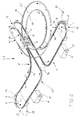
- the dynamic buffer V 1 essentially comprises a single endless conveyor 1 in the form of a roller chain 12 equipped with grippers 9, stationary guide rails 13, 14 for the roller chain with a U-shaped cross-section, a carriage 2 movable along the guide rails 13, 14 with a first 180 ° deflection 3 and a second 180 ° deflection 4 for the roller chain, an input station E with a third 180 ° deflection 5 and a first drive means 7 and an output station A with a fourth 180 ° deflection 6 and a second drive station 8 for the roller chain 12. All four 180 ° deflections 3 to 6 are arranged substantially horizontally.
- the third and fourth deflections 5, 6 define together with the connected parallel, aligned strands of the guide rails 13, 14 a kind of elongated oval OV, which is interrupted only in the middle. The interruptions are followed by a spiral or spiral region W and a vertical return R for the backbone 1 b of the roller chain 12 at.
- the roller chain 12 has a plurality of similar chain links 23 which are connected via spherical bearing 24 gimbal mobile with each other.
- a total of three guide rollers 10, 11, 25 are rotatably mounted.
- the guide roller 10 is arranged directly on the chain link 23 and engages in the groove-like depression of the guide rails 13, 14 a.
- the guide roller 11 is also arranged directly on the chain link 23 with a relation to the rotational axis of the roller 10 offset by 90 ° rotation axis and is located at the free end of the U-leg of the guide rails 13, 14, in the region of the input station E and the output station A above lies.
- the guide roller 25 is arranged on a pivot lever 26, which in turn is pivotally mounted on the chain link 23. Both the pivot axis of the pivot lever 26 and the axis of rotation of the guide roller 25 are parallel to the axis of rotation of the guide roller 11, wherein the guide roller 25 abuts approximately at the same height as the guide roller 11 at the transition between the U-leg and the connecting web of the guide rails 13, 14 , Between the chain link 23 and the pivot lever 26, a tension spring 27 is inserted, which presses the guide roller 25 against the guide rails 13, 14. In this way, each chain link 23 is guided exactly on the guide rails 13, 14 and can be moved with little force.
- a passive gripper 9 is arranged in the form of an elastic gripping tongs.
- Each gripper 9 has two gripping arms 28, 29 pivotally mounted on the chain link 23, which are urged into their gripping position by an elastic element 30.
- the recesses of the gripping arms 28, 29 are shaped such that they comprise a bottle G below the support ring T by more than 180 ° and thus fixate on the conveyor 1.
- When pushing a bottle G into a gripper 9 and pulling out a bottle G from a gripper 9 soft the gripping arms 28, 29 elastic; they therefore do not require their own forced control. Nevertheless, the bottles G are accurately and reliably fixed by the grippers 9 on the conveyor 1.
- the grippers in the area of the input station E and the output station A take the in Fig.
- the gripper 9 is located on the outside of the orbit of the conveyor 1 and that on the open side of the guide rails 13, 14. These are arranged in the region of the input station E and the output station A such that the open side of the U-profile is horizontal to the outside of the trajectory. In these areas, therefore, the weight of the bottles G and the roller chain 12 is supported by the guide rollers 10, while the guide rollers 11 and 25 take over the lateral guidance of the roller chain 12.
- the drive of the roller chain 12 is effected by two identically constructed drive means 7 and 8 in the region of the input station E and in the region of the output station A.
- Each drive means 7, 8 has two equal-sized gears 31, 32 with a vertical axis of rotation, via a gear 33 and an electric motor ME, MA can be driven with variable speed.
- the gears 31, 32 are provided on the periphery with recesses which mesh with the axes of the guide rollers 11.
- the gears 31, 32 are half the pitch t of the roller chain 12, i. the distance between two grippers 9, offset from each other to secure a uniform drive.
- the drive means 7, 8 engage in the roller chain 12 from the side of the grippers 9 and are therefore arranged on the bottle-free empty strand 1 b of the roller chain 12.
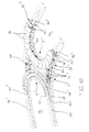
- the carriage 2 has a substantially horizontal base plate 34 and is mounted by means of several rollers 35 with a vertical or horizontal axis of rotation movable on the two guide rails 13, 14. These are in the range of movement of the carriage 2, ie arranged in the helical or spiral portion W of the conveyor track F exactly equidistant and point here with their groove-shaped opening upwards.
- the transition from the in 3 and 4 shown position of the guide rails 13, 14 with a lateral opening to the above-mentioned opening position is performed by two twist zones 36 and 37, of which the first following the input station E and the second shortly before the output station A respectively in the region of the conveyor run a is formed.
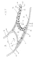
- the carriage 2 has a first 180 ° deflection 3 for the conveying strand 1 a of the roller chain and a second, opposite 180 ° deflection 4 for the return strand 1b of the roller chain 12.
- This is in Fig. 7
- the grippers and bottles are not visible.
- Their position in the region of the first deflection 3 is in Fig. 2 clearly visible.
- the bottles G run in a horizontal position over the base plate 34 along with the roller chain 12 from the stationary guide rail 14 to the stationary guide rail 13.
- two semicircular guide arches 38, 39 with a U-shaped, upwardly open cross-section are attached to the base plate 34.
- each side of the support rails 13, 14 extending wedges 41 are arranged. These wedges 41 engage the overhead guide rollers 11, which are slightly wider than the side legs of the stationary guide rails 13, 14. The position of the wedges 41 is in Fig. 3 dash-dotted lines indicated, where you have to imagine the presentation rotated by 90 ° to the right.
- the range of movement of the carriage 2 and thus the variable range of the conveyor line F is limited to the spiral or helical portion W of the guide rails 13, 14, where they are exactly equidistant and arcuate with slight slope.
- the thus defined lower end position of the carriage 2 with a minimum length of the conveyor line F is in Fig. 2 shown.
- the upper end position of the carriage 2 with maximum length of the conveyor line F is just above it. Following the upper end position follow two horizontal, parallel twisting portions 42, 43 of the guide rails 13, 14 for the empty strand 1b and then vertical return R, the roller chain 12 back into the defined by the deflections 5 and 6 normal transport plane or out of this lead upwards.
- the motor ME is driven exactly synchronously with the stretch blow molding machine 15 and the motor MA is driven exactly synchronously with the labeling machine 17.
- the drive stations 7, 8 by gear trains with the drive motors of the stretch blow molding machine 15 or the labeling machine.
- the freshly blown bottles G in the input station E divisionally by the provided in the usual way with controllable gripping arms outlet star 16 of the stretch blow molding machine 15 sequentially snapped into the gripper 9 of the roller chain 12 and so securely fixed.
- the conveying strand 1a of the roller chain 12 passes in the direction of the arrow in turn, the first twisting zone 36, a more or less long Area of the inner coil W, the first deflection 3 of the carriage 2, a more or less long portion of the outer coil W, the second twisting zone 37 and finally reaches the fourth deflection 6 and the output station A.
- the bottles G in turn through provided with controlled grippers feed star 18 of the labeling machine 17 removed from the grippers 9.
- the back strand 1 b of the roller chain 12 After passing through the inlet star 18, the back strand 1 b of the roller chain 12 passes in the direction of the arrow in turn the second drive device 8, a return R, a twist zone 42, a more or less long portion of the outer coil W, the second deflection 4 of the carriage. 2 , a more or less long portion of the inner coil W, the twisting zone 43, a return R, the first drive station 7 and finally returns to the third deflection 5 and the input station E.
- the above-described movement of the conveyor 1 takes place when the carriage 2 is stationary. Does the labeling machine 17 and thus the second drive station 8 slower than the first drive station 7 or it is stopped, so the feed strand 1 a extends between inlet station E and output station A; to the same extent shortens the empty strand 1b, whereby the carriage 2 from the in Fig. 2 moved position shown in the clockwise direction and thereby the conveying distance F and the memory contents is increased. This carriage movement continues until the two drive stations 7 and 8 work again with the same power. If the second drive station 8 operates faster than the first drive station 7, the process is reversed and the carriage 2 moves in the counterclockwise direction, whereby the conveyor line F and the memory contents is reduced.
- the bottles G remain stable due to their continuous fixation by the gripper 9 from the input station E to the output station A and can be moved at high speed in the area of the deflections. Due to the horizontal orientation of the bottles G in the spiral or coils W results in a very large packing density and thus a high storage capacity with low space requirements. If necessary, the bottles G can also in turned state to appropriate treatment machines, eg a Rinser be passed, or it already takes place within the device V 1, a treatment, eg cooling or cleaning instead.
- appropriate treatment machines eg a Rinser be passed, or it already takes place within the device V 1, a treatment, eg cooling or cleaning instead.
- lateral supports for the bottles G can be attached to the chain links 23 and / or the grippers can be made in one piece from elastic plastic.
- the twisting zones can be omitted, so that the guide rails 13, 14 in the area of the input station E and the output station A with the groove-shaped opening, as in Fig. 7 shown, pointing upwards.
- the grippers 9 are opposite to the position in FIG Fig. 3 pivoted about 90 ° to be arranged on the chain link 23 and although sufficiently far away from the guide rollers that the bottles G can be freely transferred over the carriage 2 away.
- curved cam support plates 44 are attached, as in Fig. 9 shown in another embodiment. These support plates form a substantially continuous conveying surface for the objects on which they rest.
- the slope of the helix W and the slope of the ramps 40 add up. For relatively stable items such as carton packaging for drinks, this is not a problem. For less stable objects such as filled beverage bottles, the embodiment described below is according to the Fig. 8 to 10 Particularly advantageous because here the support plates 44 in the region of the carriage 2 'experience no additional height movement.
- the dynamic buffer V 3 essentially comprises a single endless conveyor 1 in the form of a roller chain 12 'equipped with curved support plates 44, stationary guide rails 13', 14 'for the roller chain each consisting of two angularly arranged angle profiles, a carriage 2' movable along the guide rails 13 ', 14'. with a first 180 ° deflection 3 'and a second 180 ° deflection 4' for the roller chain, an input station E with a third 180 ° deflection 5 'and a first drive means 7 and an output station A with a fourth 180 ° deflection 6' and a second drive station 8 for the roller chain 12 '.
- the first and second diversion 3 ', 4' are arranged substantially horizontally, while the third and fourth deflections 5 ', 6' are substantially vertical.
- Fig. 8 schematically illustrated course of the conveyor line F with a conveying strand 1 a and a sliver strand 1b of the conveyor 1 defined, wherein the guide rails 13 ', 14' in the region of the input station E and the output station A are arranged parallel to each other.
- the helix W is equipped with several turns for increasing the storage capacity; Accordingly, the vertical return R is extended. Otherwise, the same effect and function as in the dynamic memory V 1 after Fig. 2 given.
- the entire assembly stands on several columns 46, of which only two are shown.
- the two guide rollers 10 ', 11' with a horizontal axis of rotation are arranged directly on the chain link 23 'and run on the two horizontal legs of the guide rails 13', 14 '.
- the guide roller 23 ' is arranged vertically movable at the bottom of the chain link by means of a vertical bolt 45 and is by a compression spring 47 down into the in Fig. 9 shown, fixed by stops not shown fixed lower end position.
- each chain link 23 ' Exactly on the guide rails 13', 14 'out and can be moved with little force.
- each chain link 23 ' on the horizontal, slightly upwardly cranked upper leg of each chain link 23 ', which carries the spherical bearing 24, each mounted a substantially horizontal support plate 44 for the objects to be transported.
- the Support plates 44 are concave-convex and thus curve-shaped in the horizontal direction.
- the carriage 2 ' has a substantially horizontal frame 49 and is by means of several rollers 35' with a vertical or horizontal axis of rotation movable on the two support rails 13 ', 14' stored. It has a first 180 ° deflection 3 'for the conveying strand 1a of the roller chain 12' and a second, opposite 180 ° deflection 4 'for the return strand 1b of the roller chain 12'. This is in Fig. 10 for clarity only partially shown.
- the deflections 3 ', 4' are defined by two fixed to the frame 49, semi-circular guide sheets 38 ', 39' with U-shaped, upwardly open cross-section.
- the guide sheets 38 ', 35' overlap with their end portions formed between the two angle profiles of each guide rail 13 ', 14' guide groove. They run in inclined ramps 40 ', which engage in the guide groove. By these ramps 40 ', which engage the thrust bearings 48, the movable guide rollers 25' are gently lifted upwards out of the guide groove of the guide rails 13 ', 14' and gently lowered down into the guide groove. Between the two ramps 40 'of a guide arc slide the thrust bearing 48 continuously on the bottom surface of the respective guide arc 38', 39 '. This height movement is limited to the movable guide rollers 25 ', while the chain links 23' and the support plates 44 do not leave their conveying plane.
- arcuate guide elements in the form of two parallel hold-downs 50, 51 are provided concentrically to the already described guide arches 38 ', 39', which are from above Her attack on the two guide rollers 10 ', 11' of each chain link 23 'and thus prevent a tilting movement or lifting the chain links 23' reliably.
- the guide elements can also be driven by tapping the chain movement in the region of the carriage 2 '.
- the support plates 44 dash-dotted lines indicated guide rails 53 for the objects G. If the helix W is oval-shaped, it is expedient to make the carriage 2, 2 'articulated, for example by a pivot joint in the center of the base plate 34 or of the frame 49.
- each deflection 3 ', 4' with its guide arc 38 ', 39' and other attachments by means of a hinge 57, 58 pivotally mounted on the frame 49 and by means of own rollers 35 'in the guide rails 13', 14 'engages.
- Coaxially with the joints 57, 58, deflection wheels 59, 60 can be mounted, which are looped around by the roller chain 12 'and thus absorb the tensile forces exerted by the latter.
- the guide sheets 38 ', 39' are thereby relieved.
- the grippers 9 are fixedly arranged on the roller chain 12.
- the grippers 9 in the execution after Fig. 12 movably arranged on the roller chain 12.
- two adjacent grippers 9 are combined here to form a unit 61, which in turn is pivotally mounted on lateral arms 62 of the roller chain 12.
- the units 61 are pressed against formed against the arms 62 stops 63. In this position, the connecting line between the two grippers 9 of a unit 61 extends substantially transversely to the roller chain 12, i. Connecting line and roller chain include a right or an obtuse angle.
- the units 61 are pivoted in the region of the deflections 5, 6 of the input station E and the output station A in a second position in which the connecting line between the two grippers 9 a unit 61 substantially parallel or tangential to Roller chain 12 runs.
- the objects G can easily be inserted one after the other into the grippers 9 or removed from them by the inlet star 18 or outlet star 19. This is possible due to the spreading of the units 61 due to the caused by the boom 62 distance to the roller chain 12.
- the grippers are close to each other, so that compared to a conveyor chain with rigid grippers a much higher storage capacity the same length of the roller chain 12 can be achieved.
- the roller chain 12 "after Fig. 13 differs from the roller chain 12 'after Fig. 9 and 10 essentially in that the movable guide roller 25 'is not vertically displaceable but is pivotally connected to the chain link 23 "by means of a pivoting lever 26.
- the movable guide roller 25 ' In the illustrated lower end position of the guide roller 25' in which it engages between the stationary guide rails 13 ', 14', not shown , It is by means of a snap connection 64 releasably fixed to the chain link 23 ".
- the pivot lever 26 is fixedly connected to a control thumb 65.
- a further guide roller 71 is mounted directly on the chain link 23 "underneath the support plate 44. This guide roller takes over the guidance of the roller chain 12" in the region of the deflections 3 ', 4', either by means of the guide arches 39 'or by means of the guide wheels 59, 60.
- This design allows a simple construction of a particularly smooth transition of the roller chain 12 'in the region of the carriage 2' without height movement of the support plate 44th
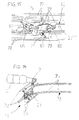
- the dynamic memory after FIGS. 14 and 15 differs from the execution 3 and 4 among other things in that here the guide rails 13 and 14 are formed by six parallel round rods 72. Further, two double lever 66, 67 are scissor-like mounted on each chain link 23. At the ends of the two double levers 66, 67 a total of four profiled guide rollers 73 are rotatably mounted.
- the guide sheets 38, 39 of the carriage 2 are formed by parallel rods 75, four in number. These are designed such that they can engage between the round bars 72 of the guide rails 13, 14 and can detect the guide rollers 73 at their tapered areas.
- the double levers 66, 67 are compressed against the force of the tension springs 74 so that they run obliquely to the round rods 72. In this spread position they are taken over by the round rods 75 and passed through the guide sheets 38, 39 and deflections 3, 4 to the other guide rail 13 and 14, respectively. There they are released from the round bars 75, after which the double lever spread and the guide is taken over again by the round bars 72.
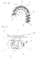
- FIGS. 14 and 15 A particularly inexpensive and reliable embodiment of a dynamic memory show the Fig. 16 to 22nd , This memory is different from the memory FIGS. 14 and 15 especially in that here the guide rails 13 and 14 are formed by two parallel tubes or rods 72 and that on each chain link 23 only one double lever 66 is pivotally mounted with profiled guide rollers 73.
- each profiled guide rollers 73 are arranged independently rotatably, such that they receive the respective round bar 72 and partially embrace.
- a tension spring 74 is inserted, which seeks to pivot the double lever 66. In doing so, it urges the guide rollers 73 against the round rods 72 Fig. 16 seeks the tension spring 74, the double lever 66 to pivot counterclockwise.
- the double lever 66 are slightly inclined to the link chain 12 and the round rods 72 and can easily compensate for slight distance changes between the attached to spacers 76 by welding or clamping rods 72.
- the Pivot axis between chain link 23 and double lever 66 is either exactly in the middle of the double lever ( Fig. 17 ) or slightly off-center ( Fig. 16 ). Under certain circumstances, the off-center arrangement brings about a better stabilization of the double levers 66, in particular with high tensile force and in the region of the deflections.
- each guide wheel 59 60 or rotatably connected rings or disks 77 bearing blocks 79 are fixed in the areas between the holes (in Fig. 18 not shown).
- 60 aligned shaft 80 is rotatably mounted in each bearing block 79 a radially to the axis of rotation of the guide wheel 59.
- a roller lever 81 is mounted with a rotatable cam roller 82.
- a two-armed control fork 83 is attached. This cooperates with control heads 84, which are arranged on both sides of the guide rollers 73 coaxial with these on the double levers 66.
- the control forks 83 are designed such that they attack the two on the same side of a double lever 66 superimposed control heads 84 substantially at the direction of movement and against the direction of movement of the roller chain 12 facing areas. In this way, an exact pivoting or fixing of the double lever 66 in the region of the deflections 3, 4 can be realized.
- the cam rollers 82 engage in two groove-like cam 85, which are mounted on the carriage 2 and 2 '.
- the cams 85 are formed such that the control forks 83 in the inlet region and outlet region between the guide wheels 59, 60 and the roller chain 12 with the inclination of the double lever 66, in which they are in engagement with the round bars 72 correspond. It is a quiet inlet and outlet of the roller chain 12 allows. In the area therebetween, however, the control forks 83 assume a stronger inclination, so that the double lever 66 corresponding to the left position in Fig. 16 in the inlet area disengaged and in the outlet area engage with the round bars 72.
- a further improvement of the guidance of the roller chain 12 on the rods 72 can be achieved by cylindrical support rollers 86, which are arranged in a fixed position on the chain links 23.
- the support rollers 86 may also carry the weight of the link chain 12, the grippers 9 and bottles G. As a result of their cylindrical shell they do not interfere with the engagement or disengagement between round bars 72 and guide rollers 73.
- the double lever 66 with respect to the chain links 23 by a snap connection 64 similar Fig. 13 releasably fixable.
- the dynamic memory after Fig. 22 differs from the store Fig. 16 to 21 especially by the fact that here the disengagement of the pivotable guide rollers 73 by mounted on the carriage 2 ramps similar Fig. 7 he follows.
- These inclined ramps 41 lift the incoming lower guide rollers 73, whereby the double lever 66 are pivoted and the rollers 73 out of engagement with the round bars 72 advised.
- the double levers 66 are fixed by the base plate of the carriage 2, over which the rollers 73 run away.
- a lowering of the lower guide rollers 73 by corresponding ramps 41 Conversely, in the outlet region of the deflections 3, 4, a lowering of the lower guide rollers 73 by corresponding ramps 41.
- the belt 88 which run over rollers 89, take the force exerted by the roller chain 12 tensile force, so that no deflection wheels are required.
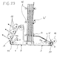
- the dynamic memory after Fig. 23 differs from the execution Fig. 2 above all, characterized in that here the central axis of the helices W of the parallel guide rails 13, 14 are arranged horizontally, whereby the helices W are, so to speak, perpendicular. This results in a particularly space-saving installation.
- the outlet region A to the conveying strand 1 a of the flexible conveyor 1 three identical outlet stars 18 are connected, each detecting the third bottle G. As a result, a three- or multi-lane distribution of the bottles G is possible.
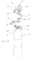
- FIGS. 24 to 28 are based in part on the embodiment Fig. 16 . 17 and 18 ,
- the outer guide rail 13 and the inner guide rail 14 are each constructed of two parallel rods 72 with spacers 76 fixed in a stationary frame with columns 46.
- each chain link 23 has two pairs of profiled guide rollers 73 which run on the rods 72, wherein the bow outer guide rollers 73 are mounted on a double lever 66, which in turn is pivotally mounted on the chain link 23.
- the inner bow guide rollers 73 are mounted directly on the chain link 23 and thus not pivotable.
- These guide rollers 73 take over the leadership of the roller chain 12 in the region of the two deflections 3, 4 of the carriage 2 (see Fig. 28 ).
- a pawl 92 is pivotally mounted, which is biased by a torsion spring 93.
- the pivot axis of the pawl 92 is parallel to the pivot axis of the double lever 66; the torsion spring 93 acts in Fig. 24 clockwise.
- the pawl 93 cooperates with a transverse pin 94 which is mounted parallel to the axis of rotation of the double lever 66 projecting on both sides.
- a control thumb 95 is provided on the pawl 92, which cooperates with a ramp 41 on the carriage 2. If the control thumb 95 encounters this ramp 41, then the pawl 92 is counter to the force of the torsion spring 93 (in Fig. 24 pivoted counterclockwise), thereby disengaged from the cross pin 94 and thus releases the double lever 66.
- Whose position is now defined in the region of the carriage 2 by an arcuate groove curve 96 attached thereto. This is designed so that the double lever 66 immediately before arriving at the deflection 3, or 4 sufficient is widely pivoted that its two guide rollers 74 can pass between the round bars 72 (position X in Fig. 28 ).
- a transversely projecting support S arranged.
- a gripper 9 accordingly Fig. 4 arranged, which has two pivotable gripping arms 28, 29 and a spring 30 acting on them in the closing direction or gripping sense.
- Fig. 24 and 25 is on each support S a support plate 44 accordingly Fig. 9 arranged on the also for mutual support, a projection 97 is formed.
- Fig. 26 is arranged on each support S a gripper 9, the gripping arms 28, 29 are integrally formed of elastic plastic.
- each support arm S a gripper 9, whose gripping arms 28, 29 are formed for the suspended transport of preferably full bottles G.
- the gripping arms 28, 29 enclose the bottleneck below the support ring T almost completely and thus ensure a stable grip of the bottles G.
- the gripping arms are provided beyond their pivot axis with counter arms 98, by which they by stationary cams 99 against the force of the spring 30 in the area the input station E and the output station A can be opened forcibly.
- the bottles G are fixed and centered positively and non-positively.
- the bottles G thus keep their position with respect to the roller chain 12 during the passage of the dynamic buffer exactly.
- the carriage 2 after Fig. 28 is as well as the slide 2 after Fig. 22 by means of a plurality of rollers 35 on the four round rods 72 of the outer guide rail 13 and the inner guide rail 14 movably guided. He has in addition to the already described ramp 41 for controlling the pawls 92 and the cam groove 96 for controlling the double lever 66 two the first and second deflection 3, 4 defining guide sheets 100, which cooperate with the guide rollers 73 mounted directly on the chain links 23 and thus deflect the roller chain 12 exclusively by means of rolling friction.
- the guide sheets 100 engage the facing sides of the guide rollers 73, while the sides facing away from each other of the guide rollers 73 cooperate with the rods 72. It is thus an overlapping or shock-free transition of the guide rollers 73 of the round bars 72 to the guide sheets 100 and vice versa possible.
Landscapes
- Engineering & Computer Science (AREA)
- Mechanical Engineering (AREA)
- Attitude Control For Articles On Conveyors (AREA)
- Specific Conveyance Elements (AREA)
- Framework For Endless Conveyors (AREA)
- Branching, Merging, And Special Transfer Between Conveyors (AREA)
Applications Claiming Priority (4)
| Application Number | Priority Date | Filing Date | Title |
|---|---|---|---|
| DE102004005180 | 2004-02-02 | ||
| DE102004043791 | 2004-09-08 | ||
| DE102004053663A DE102004053663A1 (de) | 2004-02-02 | 2004-11-03 | Vorrichtung zum dynamischen Speichern von Gegenständen |
| EP05701281.7A EP1711420B1 (fr) | 2004-02-02 | 2005-02-01 | Dispositif de stockage dynamique d'objets |
Related Parent Applications (2)
| Application Number | Title | Priority Date | Filing Date |
|---|---|---|---|
| EP05701281.7 Division | 2005-02-01 | ||
| EP05701281.7A Division-Into EP1711420B1 (fr) | 2004-02-02 | 2005-02-01 | Dispositif de stockage dynamique d'objets |
Publications (1)
| Publication Number | Publication Date |
|---|---|
| EP2380832A1 true EP2380832A1 (fr) | 2011-10-26 |
Family
ID=34809615
Family Applications (1)
| Application Number | Title | Priority Date | Filing Date |
|---|---|---|---|
| EP11174839A Withdrawn EP2380832A1 (fr) | 2004-02-02 | 2005-02-01 | Dispositif pour le stockage dynamique d'objets |
Country Status (4)
| Country | Link |
|---|---|
| EP (1) | EP2380832A1 (fr) |
| CN (1) | CN1914103B (fr) |
| DE (1) | DE102004053663A1 (fr) |
| RU (1) | RU2006131572A (fr) |
Cited By (4)
| Publication number | Priority date | Publication date | Assignee | Title |
|---|---|---|---|---|
| EP3348335A4 (fr) * | 2015-09-11 | 2019-06-12 | Hiraide Precision CO., LTD. | Dispositif de nettoyage de table de travail de type à transport tridimensionnel |
| DE102019113653A1 (de) * | 2019-05-22 | 2020-11-26 | Krones Ag | Vorrichtung zum Halten eines Behälters und Verschließvorrichtung |
| CN113911700A (zh) * | 2021-08-31 | 2022-01-11 | 广东文灿压铸科技有限公司 | 一种轿车变速箱壳体的搬运系统 |
| IT202200012296A1 (it) * | 2022-06-10 | 2023-12-10 | Europool Srl | Linea e metodo di confezionamento |
Families Citing this family (35)
| Publication number | Priority date | Publication date | Assignee | Title |
|---|---|---|---|---|
| EP1711420B1 (fr) | 2004-02-02 | 2016-04-06 | Krones AG | Dispositif de stockage dynamique d'objets |
| DE202004016069U1 (de) | 2004-10-16 | 2005-12-01 | Krones Ag | Vorrichtung zum Puffern von Gegenständen |
| DE202005013552U1 (de) | 2005-08-27 | 2005-11-03 | Krones Ag | Dynamischer Speicher für Gegenstände |
| DE102006008123A1 (de) | 2006-02-20 | 2007-08-23 | Krones Ag | Vorrichtung zum Speichern von Gegenständen |
| DE102006012148A1 (de) | 2006-03-16 | 2007-09-20 | Krones Ag | Fördermittel |
| NZ571760A (en) | 2006-04-20 | 2011-06-30 | Arrowhead Conveyor Corp Inc | A devise to transfer articles across spiral conveyors mounded on an arm with linear and arcurate movement |
| DE102006035109A1 (de) | 2006-07-29 | 2008-01-31 | Krones Ag | Fördereinrichtung |
| DE102008004775A1 (de) * | 2008-01-16 | 2009-07-23 | Krones Ag | Vorrichtung zum Transportieren von Gegenständen |
| DE102008055531A1 (de) | 2008-12-16 | 2010-06-17 | Krones Ag | Vorrichtung zum Speichern von Gegenständen innerhalb einer Verarbeitungsstrecke |
| DE102009040976A1 (de) * | 2009-09-11 | 2011-03-17 | Krones Ag | Anordnung meherer miteinander verbundener Handhabungsvorrichtungen für Artikel sowie Verfahren zum Betrieb einer solchen Anlage |
| DE102009041160B4 (de) * | 2009-09-14 | 2018-02-22 | Krones Aktiengesellschaft | Vorrichtung zum Herstellen von Flüssigkeitsbehältnissen |
| DE102009044104A1 (de) * | 2009-09-24 | 2011-03-31 | Krones Ag | Einrichtung zum Transfer von Behältern zwischen zwei Bearbeitungsstationen sowie ein Verfahren zum Transfer von Behältern zwischen zwei Bearbeitungsstationen |
| IT1397235B1 (it) * | 2010-01-08 | 2013-01-04 | Pe Labellers Spa | Unita' operativa con macchina etichettatrice e macchina riempitrice di contenitori. |
| DE102010002311A1 (de) * | 2010-02-24 | 2011-08-25 | Krones Ag, 93073 | Verfahren zum Steuern einer Etikettiervorrichtung |
| DE102010029519A1 (de) | 2010-05-31 | 2011-12-01 | Krones Ag | Behälter-Behandlungsanlage, Verfahren zum Behandeln von Behältern, und Fördereinrichtung |
| DE102010029520A1 (de) | 2010-05-31 | 2011-12-01 | Krones Ag | Behälter-Behandlungsanlage und Verfahren zum Behandeln von Behältern |
| DE102010040413A1 (de) | 2010-09-08 | 2012-03-08 | Krones Aktiengesellschaft | Fördersystem |
| EP2428471B1 (fr) | 2010-09-08 | 2013-06-05 | Krones AG | Convoyeur |
| DE102010040410A1 (de) | 2010-09-08 | 2012-03-08 | Krones Aktiengesellschaft | Fördersystem |
| PL2643247T3 (pl) * | 2010-11-23 | 2015-04-30 | Hauni Maschinenbau Ag | Element prowadzący dla łańcuchów transportowych oraz urządzenie przenośnikowe i/lub magazynowe z takimi elementami prowadzącymi |
| US9527671B2 (en) * | 2012-07-24 | 2016-12-27 | Laitram, L.L.C. | Conveyor belt for product stabilization |
| KR20160064524A (ko) * | 2014-11-28 | 2016-06-08 | 삼성전자주식회사 | 컨베이어 장치 |
| US9688482B2 (en) * | 2015-03-17 | 2017-06-27 | Illinois Tool Works Inc. | Apparatus for buffering the flow of articles |
| DE102015226141A1 (de) * | 2015-12-21 | 2017-06-22 | Krones Ag | Lineares Transportsystem mit minimaler Transportteilung |
| DE102016004405B4 (de) * | 2016-04-14 | 2019-02-14 | Khs Corpoplast Gmbh | Heizvorrichtung und Verfahren zur thermischen Konditionierung von für die Blasformung vorgesehenen Vorformlingen |
| CN107458817A (zh) * | 2017-07-27 | 2017-12-12 | 江苏新美星包装机械股份有限公司 | 一种变距传输装置及变距传输方法 |
| AT16208U1 (de) * | 2017-09-11 | 2019-03-15 | Gassner Verwaltungs Gmbh | Kettenglied, Förderkette und Kettenförderer |
| KR101947450B1 (ko) * | 2018-04-30 | 2019-02-13 | (주)에스티아이 | 케미컬 용기 자동이송장치 및 자동이송방법 |
| CN112849961B (zh) * | 2021-03-08 | 2025-06-27 | 佛山市崎林床具机械有限公司 | 一种弹簧压缩输送装置 |
| DE102022108754A1 (de) * | 2022-04-11 | 2023-10-12 | Krones Aktiengesellschaft | Behälterbehandlungsanlage |
| DE102022108753A1 (de) * | 2022-04-11 | 2023-10-12 | Krones Aktiengesellschaft | Behälterbehandlungsanlage |
| CN114955497B (zh) * | 2022-06-29 | 2024-03-29 | 昆明鼎承科技有限公司 | 一种先入先出缓存输送方法及装置 |
| CN116477329B (zh) * | 2023-04-21 | 2025-11-04 | 武汉逸飞激光智能装备有限公司 | 一种用于电芯生产的环形输送线 |
| CN117104891A (zh) * | 2023-09-18 | 2023-11-24 | 苏州纵苇科技有限公司 | 输送装置及物流输送线 |
| CN120135763B (zh) * | 2025-04-16 | 2025-12-12 | 江苏大学 | 一种基于链条拨片变距的光纤线圈运输装置 |
Citations (4)
| Publication number | Priority date | Publication date | Assignee | Title |
|---|---|---|---|---|
| US4413724A (en) | 1981-05-18 | 1983-11-08 | Mapatent, N.V. | Horizontal accumulator |
| US5429227A (en) * | 1993-07-19 | 1995-07-04 | Korber Ag | Chain conveyor |
| EP0734978A2 (fr) * | 1995-03-30 | 1996-10-02 | Jervis B. Webb International Company | Transporteur à bande entraîné par chaîne |
| EP1275603A1 (fr) | 2001-06-26 | 2003-01-15 | SIG Pack Systems AG | Accumulateur |
Family Cites Families (2)
| Publication number | Priority date | Publication date | Assignee | Title |
|---|---|---|---|---|
| DE19816239A1 (de) * | 1998-04-11 | 1999-10-14 | Krones Ag | Vorrichtung zum Einbringen und/oder Ausbringen von Behältern in bzw. aus einem Behandlungsraum |
| EP1295820B1 (fr) * | 2001-09-20 | 2005-11-30 | Sig Simonazzi S.P.A. | Dispositif de stockage temporaire d'articles dans une chaine de production |
-
2004
- 2004-11-03 DE DE102004053663A patent/DE102004053663A1/de not_active Withdrawn
-
2005
- 2005-02-01 RU RU2006131572/11A patent/RU2006131572A/ru unknown
- 2005-02-01 CN CN2005800038775A patent/CN1914103B/zh not_active Expired - Fee Related
- 2005-02-01 EP EP11174839A patent/EP2380832A1/fr not_active Withdrawn
Patent Citations (4)
| Publication number | Priority date | Publication date | Assignee | Title |
|---|---|---|---|---|
| US4413724A (en) | 1981-05-18 | 1983-11-08 | Mapatent, N.V. | Horizontal accumulator |
| US5429227A (en) * | 1993-07-19 | 1995-07-04 | Korber Ag | Chain conveyor |
| EP0734978A2 (fr) * | 1995-03-30 | 1996-10-02 | Jervis B. Webb International Company | Transporteur à bande entraîné par chaîne |
| EP1275603A1 (fr) | 2001-06-26 | 2003-01-15 | SIG Pack Systems AG | Accumulateur |
Cited By (6)
| Publication number | Priority date | Publication date | Assignee | Title |
|---|---|---|---|---|
| EP3348335A4 (fr) * | 2015-09-11 | 2019-06-12 | Hiraide Precision CO., LTD. | Dispositif de nettoyage de table de travail de type à transport tridimensionnel |
| DE102019113653A1 (de) * | 2019-05-22 | 2020-11-26 | Krones Ag | Vorrichtung zum Halten eines Behälters und Verschließvorrichtung |
| EP3753900A1 (fr) * | 2019-05-22 | 2020-12-23 | Krones Ag | Dispositif de maintien d'un récipient et dispositif de fermeture |
| US11772949B2 (en) | 2019-05-22 | 2023-10-03 | Krones Ag | Device for holding a container and closing device |
| CN113911700A (zh) * | 2021-08-31 | 2022-01-11 | 广东文灿压铸科技有限公司 | 一种轿车变速箱壳体的搬运系统 |
| IT202200012296A1 (it) * | 2022-06-10 | 2023-12-10 | Europool Srl | Linea e metodo di confezionamento |
Also Published As
| Publication number | Publication date |
|---|---|
| CN1914103A (zh) | 2007-02-14 |
| DE102004053663A1 (de) | 2005-08-18 |
| RU2006131572A (ru) | 2008-03-10 |
| CN1914103B (zh) | 2012-12-26 |
Similar Documents
| Publication | Publication Date | Title |
|---|---|---|
| EP1711420B1 (fr) | Dispositif de stockage dynamique d'objets | |
| EP2380832A1 (fr) | Dispositif pour le stockage dynamique d'objets | |
| EP3652096B1 (fr) | Dispositif de stockage et de convoyeur et procédé de fonctionnement du dispositif de stockage et de convoyeur | |
| DE60207774T2 (de) | Vorrichtung zum Fördern von Beuteln und eine endlose Kette mit Greifern für eine Füll- und Verschliessmaschine | |
| EP2623441B1 (fr) | Dispositif de stockage pour récipients et procédé de stockage de récipients | |
| EP1919805B1 (fr) | Magasin dynamique destine a des objets | |
| EP0942885B1 (fr) | Dispositif a bascule pour vider des contenants destines a des colis de detail | |
| CH694558A5 (de) | Senkrechtförderer für eine Palettiervorrichtung. | |
| EP1037834B1 (fr) | Convoyeur distributeur pour le transfert de charges isolees | |
| EP2314529B1 (fr) | Unité de transport dotée de chaînes à petits rouleaux de retenue | |
| EP2143550A1 (fr) | Dispositif de fabrication de corps creux en feuilles de plastique déformables thermoplastiques | |
| AT509425B1 (de) | Fördervorrichtung | |
| EP0161412B1 (fr) | Dispositif de transport pour convoyer des montages supports de pièces | |
| DE2935263A1 (de) | Automatische buchstapelmaschine | |
| EP0536530B1 (fr) | Machine de lavage de bouteilles | |
| EP3044132B1 (fr) | Système de transport | |
| WO2007042158A1 (fr) | Dispositif d'aiguillage pour ligne de transport | |
| DE3124600A1 (de) | Stabilisierungseinrichtung fuer die gegenstaende tragenden glieder in einem transfersystem | |
| DE19546887A1 (de) | Förderbahn für Paletten | |
| DE20114960U1 (de) | Vorrichtung zum hängenden Transport von PET-Flaschen | |
| DE3336766A1 (de) | Ein- oder auspackmaschine insbesondere fuer flaschen | |
| EP4417552B1 (fr) | Dispositif de transport de récipients à réglage de division | |
| WO1987006564A1 (fr) | Convoyeur pour le transport de pieces | |
| EP4699960A1 (fr) | Convoyeur à rouleaux pour transporter des marchandises et procédé de fonctionnement du convoyeur à rouleaux | |
| DD201401A1 (de) | Endlose transportkette mit mindestens einem mitnahmezapfen |
Legal Events
| Date | Code | Title | Description |
|---|---|---|---|
| AC | Divisional application: reference to earlier application |
Ref document number: 1711420 Country of ref document: EP Kind code of ref document: P |
|
| AK | Designated contracting states |
Kind code of ref document: A1 Designated state(s): AT BE BG CH CY CZ DE DK EE ES FI FR GB GR HU IE IS IT LI LT LU MC NL PL PT RO SE SI SK TR |
|
| PUAI | Public reference made under article 153(3) epc to a published international application that has entered the european phase |
Free format text: ORIGINAL CODE: 0009012 |
|
| 17P | Request for examination filed |
Effective date: 20120322 |
|
| 17Q | First examination report despatched |
Effective date: 20170919 |
|
| RIC1 | Information provided on ipc code assigned before grant |
Ipc: B65G 17/38 20060101ALI20190320BHEP Ipc: B67C 3/22 20060101AFI20190320BHEP Ipc: B65G 47/51 20060101ALI20190320BHEP Ipc: B65G 21/18 20060101ALI20190320BHEP |
|
| STAA | Information on the status of an ep patent application or granted ep patent |
Free format text: STATUS: THE APPLICATION IS DEEMED TO BE WITHDRAWN |
|
| 18D | Application deemed to be withdrawn |
Effective date: 20190903 |