EP1994258B1 - Kohlenwasserstoff-wiedergewinnungstechniken - Google Patents
Kohlenwasserstoff-wiedergewinnungstechniken Download PDFInfo
- Publication number
- EP1994258B1 EP1994258B1 EP07752834.7A EP07752834A EP1994258B1 EP 1994258 B1 EP1994258 B1 EP 1994258B1 EP 07752834 A EP07752834 A EP 07752834A EP 1994258 B1 EP1994258 B1 EP 1994258B1
- Authority
- EP
- European Patent Office
- Prior art keywords
- vessel
- gas
- hydrocarbons
- oil
- hydrocarbon
- Prior art date
- Legal status (The legal status is an assumption and is not a legal conclusion. Google has not performed a legal analysis and makes no representation as to the accuracy of the status listed.)
- Not-in-force
Links
Images


Classifications
-
- B—PERFORMING OPERATIONS; TRANSPORTING
- B63—SHIPS OR OTHER WATERBORNE VESSELS; RELATED EQUIPMENT
- B63C—LAUNCHING, HAULING-OUT, OR DRY-DOCKING OF VESSELS; LIFE-SAVING IN WATER; EQUIPMENT FOR DWELLING OR WORKING UNDER WATER; MEANS FOR SALVAGING OR SEARCHING FOR UNDERWATER OBJECTS
- B63C7/00—Salvaging of disabled, stranded, or sunken vessels; Salvaging of vessel parts or furnishings, e.g. of safes; Salvaging of other underwater objects
-
- B—PERFORMING OPERATIONS; TRANSPORTING
- B01—PHYSICAL OR CHEMICAL PROCESSES OR APPARATUS IN GENERAL
- B01D—SEPARATION
- B01D17/00—Separation of liquids, not provided for elsewhere, e.g. by thermal diffusion
- B01D17/02—Separation of non-miscible liquids
- B01D17/04—Breaking emulsions
-
- B—PERFORMING OPERATIONS; TRANSPORTING
- B08—CLEANING
- B08B—CLEANING IN GENERAL; PREVENTION OF FOULING IN GENERAL
- B08B9/00—Cleaning hollow articles by methods or apparatus specially adapted thereto
- B08B9/08—Cleaning containers, e.g. tanks
-
- B—PERFORMING OPERATIONS; TRANSPORTING
- B63—SHIPS OR OTHER WATERBORNE VESSELS; RELATED EQUIPMENT
- B63C—LAUNCHING, HAULING-OUT, OR DRY-DOCKING OF VESSELS; LIFE-SAVING IN WATER; EQUIPMENT FOR DWELLING OR WORKING UNDER WATER; MEANS FOR SALVAGING OR SEARCHING FOR UNDERWATER OBJECTS
- B63C7/00—Salvaging of disabled, stranded, or sunken vessels; Salvaging of vessel parts or furnishings, e.g. of safes; Salvaging of other underwater objects
- B63C7/006—Emptying the contents of sunken, stranded, or disabled vessels, e.g. by engaging the vessel; Underwater collecting of buoyant contents, such as liquid, particulate or gaseous contents, escaping from sunken vessels, e.g. using funnels, or tents for recovery of escaping hydrocarbons
-
- B—PERFORMING OPERATIONS; TRANSPORTING
- B67—OPENING, CLOSING OR CLEANING BOTTLES, JARS OR SIMILAR CONTAINERS; LIQUID HANDLING
- B67D—DISPENSING, DELIVERING OR TRANSFERRING LIQUIDS, NOT OTHERWISE PROVIDED FOR
- B67D7/00—Apparatus or devices for transferring liquids from bulk storage containers or reservoirs into vehicles or into portable containers, e.g. for retail sale purposes
Definitions
- This disclosure relates generally to a technique for recovering hydrocarbons from a vessel. More specifically, this disclosure relates to a method for recovering hydrocarbons from a storage vessel by displacement.
- Offshore drilling and production platforms used for recovering oil from subterranean formations disposed beneath ocean water include a number of structural support legs for supporting a plurality of work areas. Generally, below the work areas, a plurality of hollow concrete multi-cell structures may sit on the seabed floor. The hollow concrete multi-cell structures may be large, in some cases including over eighty cells, each cell reaching volumes of thousands of cubic meters.
- the hollow concrete multi-cell structures may have been used to separate hydrocarbons from water, store hydrocarbons, or otherwise collect a hydrocarbon source. As a function of operation, hydrocarbons may become trapped in the hollow concrete multi-cell structures. The hydrocarbons trapped in the hollow multi-cell structures are often referred to in the industry as "attic oil.”
- abandoned storage vessels could remain partially filled with residual hydrocarbons.
- One such source of abandoned hydrocarbons occurs in storage vessels awaiting decommission. Prior to decommissioning, the remaining hydrocarbons in the storage vessels must be removed. Additionally, to prevent contamination of the ecology around the hollow multi-cell structures, the decommissioning of storage vessels must occur in an environmentally clean manner.
- the '314 patent and the '627 patent describe methods of injecting gas into a subterranean formation to recover oil trapped therein, the methods both involve drilling a well into the formation, an option that is not available when removing oil from a storage vessel on the seabed floor. Further, the prior disclosures remove the oil through an export location drilled through the top of a formation. On oil platforms, rather than being located on the top of the storage vessels, the export location is generally located below the hydrocarbon layer, thereby preventing removal though the simple pumping described in prior disclosures.
- Document GB 22 8302 describes a further method according to the preamble of claim 1.
- embodiments disclosed herein relate to a method for extracting hydrocarbons from a vessel.
- the method includes displacing a hydrocarbon source with a material of density different than that of the hydrocarbon source and recovering the hydrocarbons from the vessel.
- the hydrocarbon source is oil.
- Embodiments disclosed herein relate to a method for extracting hydrocarbons from a vessel by gas displacement through chemical introduction.
- the method includes introducing hydrochloric acid and sodium bicarbonate into a vessel, producing carbon dioxide from the reaction of the hydrochloric acid and the sodium bicarbonate, displacing a hydrocarbon source inside the vessel, and recovering the hydrocarbon source from the vessel.
- embodiments disclosed herein relate to methods for removing hydrocarbons from vessels. More specifically, embodiments disclosed herein relate to the removal of hydrocarbons from vessels through displacement.
- a first material e.g . hydrocarbons
- a second, more dense material e.g . water
- an export location e.g . an export pipe
- the first material may not be efficiently extracted without bringing the first material layer to the same level as the export location.
- a first material may be layered in a vessel above an export location.
- a second material that is less dense than the first material may be introduced into the vessel.
- the first material may be displaced such that the first material comes into contact with the export location. The first material may then be recovered from the vessel.
- a vessel may contain a first material located below an export location.
- it may be beneficial to introduce a higher density material to displace a lower density material, such that the lower density material rises in the vessel.
- the displaced material may be removed accordingly.
- a vessel may contain several materials of differing densities.
- a vessel may contain materials of three different densities layered therein.
- a higher density material may be introduced such that the lighter material moves upward in the vessel. Upon reaching an export location, the lighter material may then be recovered as described above.
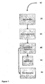
- FIGS. 1 through 6 relate to an embodiment of the present disclosure involving hydrocarbon extraction by displacement resulting from gas injection.
- a gas may be injected 20 into a storage vessel that contains a hydrocarbon source as described above.
- the gas may then displace 30 the water and hydrocarbon layer, bringing the hydrocarbon layer into fluid contact with an export pipe.
- the hydrocarbons may then be extracted 40 from the storage vessel.
- water may be reintroduced 50 into the storage vessel.
- the water replacement 50 may be provided from a header tank from an external pump, or by any means known to one of ordinary skill in the art.
- a gas absorption 60 chemical may be introduced into the storage vessel to remove any gas that remains from gas injection 20. While the described method of hydrocarbon extraction includes the direct injection of gas, other embodiments employing other processes of gas displacement may be foreseen, and are within the scope of the present disclosure.
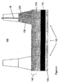
- Oil platform storage system 100 includes a plurality of hollow concrete multi-cell structures (storage vessels) 110, an export pipe 120, a header tank pipe, and a header tank 130.
- the plurality of storage vessels 110 may be fluidly connected to each other by interconnecting holes (not shown in detail).
- a single export pipe 120 may be connected to a plurality of storage vessels 110, multiple export pipes 120 may connect to groups of storage vessels 110, an export pipe 120 may be connected to each storage vessel 110, or multiple export pipes 120 may be connected to an individual storage vessel 110.
- header tank 130 may be fluidly connected to at least one of storage vessels 110, and may contain additional water 135, among other fluids.
- oil platform storage system 100 may contain, among other substances, water 135 and hydrocarbons (e.g . attic oil) 140.
- hydrocarbons 140 e.g . attic oil
- hydrocarbons 140 have a lower specific gravity than water 135.
- the hydrocarbons 140 may separate from the water 135 and form a hydrocarbon layer 145.
- gas 150 may be injected into storage vessels 110 through export pipe 120.
- export pipe 120 may be located below hydrocarbon layer 145, the gas 150 will enter oil platform storage system 100 at a location below hydrocarbon layer 145. Because the specific gravity of gas 150 is less than the specific gravity of water 135, the gas will rise through the oil platform storage system 100 as illustrated by A.
- the displacement material is a gas, it should be realized that the material may be any liquid, solid, gas, or mixture thereof with a density such as to displace the hydrocarbon layer as desired.
- the gas 150 begins to displace hydrocarbon layer 145. Because the specific gravity of gas 150 is less than the specific gravity of hydrocarbons 140, the hydrocarbon layer 145 may be displaced from the top of storage vessel 110, therein forced down in storage vessels 110 toward export pipe 120. When gas 150 displaces hydrocarbon layer 145, some water 135 may be forced out of storage vessels 110 through the header tank pipe (illustrated by B).
- hydrocarbons 140 may contact, or otherwise communicate with export pipe 120.
- an external pump (not separately shown) connected to export pipe 120 may then begin extracting hydrocarbons 140 from storage vessel 110. Hydrocarbons 140 may then be transferred to the surface, or to another location, for storage and/or further processing.
- additional water may be introduced into storage vessel 110 from a header tank 130 through the header tank pipe.
- Header tank 130 is typically present in at least one of the legs of an oil platform.
- the header tank 130 may be fluidly connected to the storage vessels 110, such that water may flow therebetween. While this embodiment illustrates the reintroduction of water into storage vessels 110, other embodiments may be foreseen wherein the storage vessels are left empty, contain residual gas, or contain other substances.
- a layer of water 155 may be present beneath hydrocarbon layer 145.
- hydrocarbons 140 are extracted from storage vessel 110, small amounts of water may also be extracted.
- the mixture of water 135 and hydrocarbons 140 may then be transferred to an oil/water separation unit (not shown) located outside of storage vessel 110.
- chemicals may be introduced with gas 150 into storage vessels 110 to prevent the contamination of hydrocarbons 140 by water 135.
- gas absorbing chemical 160 injection of a gas absorbing chemical 160, in accordance with one embodiment of the present disclosure, is shown.
- the flow direction of the external pump may be reversed, and gas absorbing chemical 160 may be introduced into storage vessel 110.
- Gas absorbing chemical 160 may then absorb gas 150, thereby allowing replacement water to fill open areas in storage vessel 110.
- the absorbing chemical may be a gas, liquid, solid, or any mixture thereof that may absorb the injected displacement material.
- gas absorbing chemical 160 may include potassium hydroxide (KOH), ammonium hydroxide (NH 4 OH), and/or ammonium chloride (NH 4 Cl).
- KOH potassium hydroxide
- NH 4 OH ammonium hydroxide
- NH 4 Cl ammonium chloride
- the introduction of KOH or NH 4 OH removes carbon dioxide (CO 2 ) from storage vessel 110.
- NH 4 Cl prevents the formation of water-insoluble mineral scales (e.g . magnesium hydroxide (Mg(OH) 2 )), which may result from mixing seawater and KOH.
- gas absorbing chemical 160 may include methanol (CH 3 OH). The introduction of CH 3 OH to the KOH and NH 4 Cl or NH 4 OH solution reduces the specific gravity of the solution, thereby allowing the solution to more easily move throughout storage vessels 110.
- the introduction of CH 3 OH may also increase the rate of contact between the solution and the gas, therein speeding the absorption of the gas 150.
- the introduction of potassium hydroxide and ammonium chloride may be one method of removing carbon dioxide from storage vessel 110, however, embodiments employing other chemicals, or no chemicals, may be foreseen, and are within the scope of this disclosure.
- While introduction of a gas absorbing chemical 160 may provide environmental or other benefits in certain applications (e.g . oil platform or storage tank decommissioning), it should be realized that embodiments that do not include use of a gas absorbing chemical 160 are within the scope of this disclosure. For example, in certain applications, it may be more economically efficient to leave the gas, whether injected or produced by chemical reaction, in the storage vessel 110. However, in embodiments that use a gas absorbing chemical, CO 2 may be preferable because CO 2 may be easily reabsorbed by aqueous solutions that may contain alkali metal hydroxide.
- Figures 1 through 6 illustrate a method of extracting hydrocarbons using gas injection
- other embodiments may be foreseen wherein at least one chemical that produces a gas is introduced to storage vessel 110.
- Figure 7 a block diagram of chemical gas production in accordance with an embodiment of the present disclosure is shown.
- a method of hydrocarbon recovery 700 may include a chemical solution, including hydrochloric acid (HCl) and sodium bicarbonate (NaHCO 3 ), being introduced into the storage vessel.
- a chemical solution including hydrochloric acid (HCl) and sodium bicarbonate (NaHCO 3 )
- HCl hydrochloric acid
- NaHCO 3 sodium bicarbonate
- a gas CO 2
- the gas may then rise through the storage vessel, contacting the hydrocarbons, thereby displacing 740 the hydrocarbon layer.
- the hydrocarbons may then be extracted 750, and water may then replace 760 the volume left by the hydrocarbons, as described above.
- a gas absorption 770 chemical/solution may be introduced into the storage vessel to absorb 780 any gas that remains from gas production 730.
- the gas absorption chemical may include KOH, NH 4 Cl, NH 4 OH, and CH 3 OH.
- the described method of hydrocarbon extraction includes the production of gas by the reaction of hydrochloric acid and sodium bicarbonate, embodiments employing other chemicals that produce gases may be foreseen, and are within the scope of this disclosure. Further embodiments may include, for example, a range of metal salts of bicarbonates and carbonates, minerals and organic acids, surfactant derived foams, low dense mobile gels, gases (direct or within a deformable bladder), materials such as styrene beads, and thermally sensitive hydrocarbon particles.
- embodiments of the aforementioned methods may increase the rate of hydrocarbon extraction from vessels located on land, in the water, or connected to oil platforms. Further, because the disclosed methods may prevent the escape of hydrocarbons into the environment, certain embodiments may provide a clean process for use during the decommissioning of oil platforms and/or removal of hydrocarbons from land based vessels. Finally, because embodiments of the present disclosure may increase the yield of hydrocarbons during recovery, the operation may pay for itself, or even generate a profit.
Landscapes
- Engineering & Computer Science (AREA)
- Mechanical Engineering (AREA)
- Ocean & Marine Engineering (AREA)
- Physics & Mathematics (AREA)
- Thermal Sciences (AREA)
- Chemical & Material Sciences (AREA)
- Chemical Kinetics & Catalysis (AREA)
- Gas Separation By Absorption (AREA)
- Production Of Liquid Hydrocarbon Mixture For Refining Petroleum (AREA)
- Organic Low-Molecular-Weight Compounds And Preparation Thereof (AREA)
- Transition And Organic Metals Composition Catalysts For Addition Polymerization (AREA)
- Filling Or Discharging Of Gas Storage Vessels (AREA)
Claims (12)
- Verfahren zum Wiedergewinnen von Kohlenwasserstoffen aus einem Gefäß (110), wobei das Verfahren umfasst:Verdrängen einer Kohlenwasserstoffquelle (140) mit einem Gas (150),wobei das Verdrängen umfasst: Einspritzen von Salzen und Säuren in das Gefäß (110); undErzeugen des Gases aus der Reaktion der Salze und der Säuren,wobei das Gas (150) eine Dichte aufweist, die nicht gleich der der Kohlenwasserstoffquelle (140) ist; undWiedergewinnen der Kohlenwasserstoffquelle (140) aus dem Gefäß (110),dadurch gekennzeichnet, dass die Salze aus der Gruppe ausgewählt werden, die Metallsalze von Bikarbonaten und Karbonaten umfasst.
- Verfahren nach Anspruch 1, wobei die Salze Natriumbikarbonat umfassen und die Säuren Chlorwasserstoffsäure umfassen.
- Verfahren nach Anspruch 1, wobei das Gefäß (110) an einer Ölplattform (100) befestigt ist.
- Verfahren nach Anspruch 1, wobei die Kohlenwasserstoffquelle Öl ist.
- Verfahren nach Anspruch 1, das ferner umfasst:Einspritzen einer materialabsorbierenden Chemikalie (160) in das Gefäß (110); undEntfernen des Gases (150) mit der materialabsorbierenden Chemikalie (160).
- Verfahren nach Anspruch 5, wobei die materialabsorbierende Chemikalie (160) Kaliumhydroxid und/oder Ammoniumchlorid und/oder Ammoniumhydroxid oder/oder Methanol und/oder Kombinationen davon umfasst.
- Verfahren nach Anspruch 1, das ferner das Trennen der Kohlenwasserstoffe (140) von Wasser (135) in einem Abscheidersystem umfasst.
- Verfahren nach Anspruch 1, wobei sich das Gefäß (110) an Land befindet.
- Verfahren nach Anspruch 1, das ferner umfasst:Einleiten von Hydrochlorsäure und Natriumbikarbonat in das Gefäß (110) undErzeugen von Kohlendioxid aus der Reaktion der Chlorwasserstoffsäure und des Natriumbikarbonats.
- Verfahren nach Anspruch 9, das ferner das Einspritzen von Kaliumhydroxid in das Gefäß (110) umfasst.
- Verfahren nach Anspruch 9, das ferner das Einspritzen von Ammoniumhydroxid in das Gefäß (110) umfasst.
- Verfahren nach Anspruch 9, das ferner das Einspritzen von Methanol in das Gefäß (110) umfasst.
Applications Claiming Priority (3)
| Application Number | Priority Date | Filing Date | Title |
|---|---|---|---|
| US78122606P | 2006-03-10 | 2006-03-10 | |
| US11/684,060 US8062510B2 (en) | 2006-03-10 | 2007-03-09 | Hydrocarbon recovery techniques |
| PCT/US2007/006163 WO2007106421A1 (en) | 2006-03-10 | 2007-03-12 | Hydrocarbon recovery techniques |
Publications (3)
| Publication Number | Publication Date |
|---|---|
| EP1994258A1 EP1994258A1 (de) | 2008-11-26 |
| EP1994258A4 EP1994258A4 (de) | 2012-12-19 |
| EP1994258B1 true EP1994258B1 (de) | 2016-10-12 |
Family
ID=38477841
Family Applications (1)
| Application Number | Title | Priority Date | Filing Date |
|---|---|---|---|
| EP07752834.7A Not-in-force EP1994258B1 (de) | 2006-03-10 | 2007-03-12 | Kohlenwasserstoff-wiedergewinnungstechniken |
Country Status (9)
| Country | Link |
|---|---|
| US (1) | US8062510B2 (de) |
| EP (1) | EP1994258B1 (de) |
| AU (1) | AU2007225252B2 (de) |
| BR (1) | BRPI0708757B1 (de) |
| CA (1) | CA2645295C (de) |
| EA (1) | EA017897B1 (de) |
| MX (1) | MX2008011536A (de) |
| NO (1) | NO341087B1 (de) |
| WO (1) | WO2007106421A1 (de) |
Families Citing this family (1)
| Publication number | Priority date | Publication date | Assignee | Title |
|---|---|---|---|---|
| CN113431534B (zh) * | 2021-08-09 | 2022-11-08 | 北京科技大学 | 一种低渗致密油藏co2吞吐选井方法 |
Family Cites Families (22)
| Publication number | Priority date | Publication date | Assignee | Title |
|---|---|---|---|---|
| US1393507A (en) * | 1919-09-15 | 1921-10-11 | Cornell Fred | Oil service-fountain |
| US1592324A (en) * | 1920-05-04 | 1926-07-13 | Doherty Res Co | Treatment and refining of mineral oils |
| DE1255333B (de) * | 1924-12-25 | 1967-11-30 | Deutsche Erdoel Ag | Vorrichtung zur Bestimmung der Hoehenlage der Kontaktflaeche zwischen Salzwasser undFluessiggas in unterirdischen Fluessiggasspeichern |
| US2497946A (en) * | 1943-02-09 | 1950-02-21 | Dravo Corp | Purging of hydrocarbon-containing chambers |
| US3608773A (en) * | 1968-04-29 | 1971-09-28 | Ashland Oil Inc | Coated tank |
| US3654951A (en) * | 1970-07-01 | 1972-04-11 | Texaco Inc | Liquid storage facility including self-actuating discharge conduit |
| GB1384881A (en) * | 1971-01-19 | 1975-02-26 | Clegg J R | Method of removing liquid from vessels |
| US3745770A (en) * | 1971-12-08 | 1973-07-17 | Dow Chemical Co | Method for the subterranean storage and withdrawal of a liquid |
| US3890796A (en) * | 1972-03-03 | 1975-06-24 | Said Vincent E Rossitto By Sai | Method for removing liquid contaminants from a submerged tank |
| JPH068640B2 (ja) | 1984-10-08 | 1994-02-02 | 瓜生製作株式会社 | 密閉容器への注油法 |
| US4679627A (en) * | 1985-08-12 | 1987-07-14 | Harrison William M | Method of oil recovery |
| US4676314A (en) * | 1985-12-06 | 1987-06-30 | Resurrection Oil Corporation | Method of recovering oil |
| KR960700438A (ko) * | 1993-01-29 | 1996-01-20 | 타게 마그누손 | 냉동기와 열 펌프로부터 오일을 정화시키기 위한 방법과 장치 |
| BR9405446A (pt) * | 1993-06-25 | 1999-09-08 | N Proizv Biotekhinvest | Processo de extração de hidrocarbonetos de formações subterrneas. |
| BR9304238A (pt) * | 1993-10-15 | 1995-06-06 | Petroleo Brasileiro Sa | Processo termo-químico de limpeza de tanques de armazenamento |
| US5725054A (en) * | 1995-08-22 | 1998-03-10 | Board Of Supervisors Of Louisiana State University And Agricultural & Mechanical College | Enhancement of residual oil recovery using a mixture of nitrogen or methane diluted with carbon dioxide in a single-well injection process |
| US5778977A (en) * | 1997-01-03 | 1998-07-14 | Marathon Oil Company | Gravity concentrated carbon dioxide for process |
| US5927404A (en) * | 1997-05-23 | 1999-07-27 | Exxon Production Research Company | Oil recovery method using an emulsion |
| RU2125154C1 (ru) | 1997-06-16 | 1999-01-20 | Закрытое акционерное общество "Интойл" | Способ разработки нефтяной залежи |
| NO305859B1 (no) * | 1997-10-21 | 1999-08-09 | Svein Olaf Lie | Luft og gassbeholder og fremgangsmÕte for drenering av overgangsslange mellom tanker |
| RU2205948C1 (ru) | 2001-10-31 | 2003-06-10 | Шарифуллин Фарид Абдуллович | Способ разработки нефтяной залежи |
| WO2004083103A1 (en) * | 2003-03-19 | 2004-09-30 | Scepter Corporation | Fluid transfer apparatus |
-
2007
- 2007-03-09 US US11/684,060 patent/US8062510B2/en not_active Expired - Fee Related
- 2007-03-12 EA EA200870345A patent/EA017897B1/ru not_active IP Right Cessation
- 2007-03-12 BR BRPI0708757-8A patent/BRPI0708757B1/pt not_active IP Right Cessation
- 2007-03-12 AU AU2007225252A patent/AU2007225252B2/en not_active Ceased
- 2007-03-12 WO PCT/US2007/006163 patent/WO2007106421A1/en not_active Ceased
- 2007-03-12 MX MX2008011536A patent/MX2008011536A/es active IP Right Grant
- 2007-03-12 CA CA2645295A patent/CA2645295C/en not_active Expired - Fee Related
- 2007-03-12 EP EP07752834.7A patent/EP1994258B1/de not_active Not-in-force
-
2008
- 2008-10-09 NO NO20084238A patent/NO341087B1/no not_active IP Right Cessation
Also Published As
| Publication number | Publication date |
|---|---|
| AU2007225252B2 (en) | 2011-03-24 |
| EA200870345A1 (ru) | 2009-06-30 |
| MX2008011536A (es) | 2009-03-26 |
| CA2645295A1 (en) | 2007-09-20 |
| NO20084238L (no) | 2008-11-28 |
| AU2007225252A1 (en) | 2007-09-20 |
| EA017897B1 (ru) | 2013-04-30 |
| BRPI0708757B1 (pt) | 2018-01-30 |
| NO341087B1 (no) | 2017-08-21 |
| BRPI0708757A2 (pt) | 2011-06-14 |
| WO2007106421A1 (en) | 2007-09-20 |
| US8062510B2 (en) | 2011-11-22 |
| US20070209970A1 (en) | 2007-09-13 |
| CA2645295C (en) | 2011-08-09 |
| EP1994258A4 (de) | 2012-12-19 |
| EP1994258A1 (de) | 2008-11-26 |
Similar Documents
| Publication | Publication Date | Title |
|---|---|---|
| US11053779B2 (en) | Hydrate solid-state fluidization mining method and system under underbalanced reverse circulation condition | |
| US11156064B2 (en) | Natural gas hydrate solid-state fluidization mining method and system under underbalanced positive circulation condition | |
| CN105625998B (zh) | 一种海底天然气水合物稳定层逆向开采方法及其开采设备 | |
| EA031016B1 (ru) | Способ добычи углеводородов с использованием каверн | |
| US10683736B2 (en) | Method and system for recovering gas in natural gas hydrate exploitation | |
| JP5316878B2 (ja) | メタンハイドレートからのメタンガス生産装置及びこれを用いたメタンハイドレートからのメタンガス生産方法 | |
| JP5538269B2 (ja) | メタンハイドレートからのメタンガス採取装置及びメタンハイドレートからのメタンガス採取方法 | |
| WO2019134220A1 (zh) | 一种天然气水合物开采采气方法及系统 | |
| CN101016841A (zh) | 一种开采天然气水合物的方法及装置 | |
| JP2009274047A (ja) | 炭酸ガスの地中貯留システム | |
| CN110821448A (zh) | 一种海相天然气水合物的开采方法及开采装置 | |
| CN102337895A (zh) | 一种开采海洋天然气水合物的方法与装置 | |
| CN111395962A (zh) | 一种海域天然气水合物气举反循环钻井系统及开采方法 | |
| RU2514339C1 (ru) | Способ создания и эксплуатации подземного хранилища газа | |
| JP3908780B1 (ja) | 二酸化炭素溶解水による水溶性天然ガスの回収方法 | |
| CN112647900B (zh) | 一种无人值守全自动水合物降压开采系统 | |
| EP1994258B1 (de) | Kohlenwasserstoff-wiedergewinnungstechniken | |
| CN109854212B (zh) | 开采天然气水合物的方法 | |
| US20090205823A1 (en) | Process for enhancing the production of oil from depleted, fractured reservoirs using surfactants and gas pressurization | |
| CN118564217A (zh) | 一种基于二氧化碳深海采矿的氢气绿色开采方法及系统 | |
| CN116357503B (zh) | 一种波浪能利用与二氧化碳封存技术相结合的系统 | |
| US9303504B2 (en) | In-situ artificial pressurization of a well with carbon dioxide recycling to increase oil production | |
| CN116122781B (zh) | 一种实现下伏游离气与海洋水合物联合开采装置与方法 | |
| CN108661607A (zh) | 一种耦合破碎溶液冲洗开采海洋天然气水合物藏的方法 | |
| RU2857351C1 (ru) | Способ добычи газа из скважины на поздних этапах её эксплуатации |
Legal Events
| Date | Code | Title | Description |
|---|---|---|---|
| PUAI | Public reference made under article 153(3) epc to a published international application that has entered the european phase |
Free format text: ORIGINAL CODE: 0009012 |
|
| 17P | Request for examination filed |
Effective date: 20080331 |
|
| AK | Designated contracting states |
Kind code of ref document: A1 Designated state(s): AT BE BG CH CY CZ DE DK EE ES FI FR GB GR HU IE IS IT LI LT LU LV MC MT NL PL PT RO SE SI SK TR |
|
| RAP1 | Party data changed (applicant data changed or rights of an application transferred) |
Owner name: M-I L.L.C. Owner name: OILFILED MINERAL SOLUTIONS LIMITED |
|
| RAP1 | Party data changed (applicant data changed or rights of an application transferred) |
Owner name: OILFILED MINERAL SOLUTIONS LIMITED Owner name: M-I PRODUCTION CHEMICALS UK LIMITED |
|
| DAX | Request for extension of the european patent (deleted) | ||
| RAP1 | Party data changed (applicant data changed or rights of an application transferred) |
Owner name: OILFIELD MINERAL SOLUTIONS LIMITED Owner name: M-I PRODUCTION CHEMICALS UK LIMITED |
|
| A4 | Supplementary search report drawn up and despatched |
Effective date: 20121120 |
|
| RIC1 | Information provided on ipc code assigned before grant |
Ipc: E21B 43/25 20060101ALI20121114BHEP Ipc: B01D 17/04 20060101ALI20121114BHEP Ipc: E21B 43/16 20060101AFI20121114BHEP Ipc: E21B 37/00 20060101ALI20121114BHEP Ipc: B08B 9/08 20060101ALI20121114BHEP Ipc: B63C 7/00 20060101ALI20121114BHEP |
|
| 17Q | First examination report despatched |
Effective date: 20130731 |
|
| GRAP | Despatch of communication of intention to grant a patent |
Free format text: ORIGINAL CODE: EPIDOSNIGR1 |
|
| INTG | Intention to grant announced |
Effective date: 20160519 |
|
| GRAS | Grant fee paid |
Free format text: ORIGINAL CODE: EPIDOSNIGR3 |
|
| GRAA | (expected) grant |
Free format text: ORIGINAL CODE: 0009210 |
|
| AK | Designated contracting states |
Kind code of ref document: B1 Designated state(s): AT BE BG CH CY CZ DE DK EE ES FI FR GB GR HU IE IS IT LI LT LU LV MC MT NL PL PT RO SE SI SK TR |
|
| REG | Reference to a national code |
Ref country code: GB Ref legal event code: FG4D |
|
| REG | Reference to a national code |
Ref country code: CH Ref legal event code: EP |
|
| REG | Reference to a national code |
Ref country code: AT Ref legal event code: REF Ref document number: 836707 Country of ref document: AT Kind code of ref document: T Effective date: 20161015 |
|
| REG | Reference to a national code |
Ref country code: IE Ref legal event code: FG4D |
|
| REG | Reference to a national code |
Ref country code: DE Ref legal event code: R096 Ref document number: 602007048293 Country of ref document: DE |
|
| REG | Reference to a national code |
Ref country code: LT Ref legal event code: MG4D |
|
| REG | Reference to a national code |
Ref country code: NL Ref legal event code: MP Effective date: 20161012 |
|
| PG25 | Lapsed in a contracting state [announced via postgrant information from national office to epo] |
Ref country code: LV Free format text: LAPSE BECAUSE OF FAILURE TO SUBMIT A TRANSLATION OF THE DESCRIPTION OR TO PAY THE FEE WITHIN THE PRESCRIBED TIME-LIMIT Effective date: 20161012 |
|
| REG | Reference to a national code |
Ref country code: AT Ref legal event code: MK05 Ref document number: 836707 Country of ref document: AT Kind code of ref document: T Effective date: 20161012 |
|
| PG25 | Lapsed in a contracting state [announced via postgrant information from national office to epo] |
Ref country code: SE Free format text: LAPSE BECAUSE OF FAILURE TO SUBMIT A TRANSLATION OF THE DESCRIPTION OR TO PAY THE FEE WITHIN THE PRESCRIBED TIME-LIMIT Effective date: 20161012 Ref country code: LT Free format text: LAPSE BECAUSE OF FAILURE TO SUBMIT A TRANSLATION OF THE DESCRIPTION OR TO PAY THE FEE WITHIN THE PRESCRIBED TIME-LIMIT Effective date: 20161012 Ref country code: GR Free format text: LAPSE BECAUSE OF FAILURE TO SUBMIT A TRANSLATION OF THE DESCRIPTION OR TO PAY THE FEE WITHIN THE PRESCRIBED TIME-LIMIT Effective date: 20170113 |
|
| PG25 | Lapsed in a contracting state [announced via postgrant information from national office to epo] |
Ref country code: IS Free format text: LAPSE BECAUSE OF FAILURE TO SUBMIT A TRANSLATION OF THE DESCRIPTION OR TO PAY THE FEE WITHIN THE PRESCRIBED TIME-LIMIT Effective date: 20170212 Ref country code: ES Free format text: LAPSE BECAUSE OF FAILURE TO SUBMIT A TRANSLATION OF THE DESCRIPTION OR TO PAY THE FEE WITHIN THE PRESCRIBED TIME-LIMIT Effective date: 20161012 Ref country code: BE Free format text: LAPSE BECAUSE OF FAILURE TO SUBMIT A TRANSLATION OF THE DESCRIPTION OR TO PAY THE FEE WITHIN THE PRESCRIBED TIME-LIMIT Effective date: 20161012 Ref country code: PL Free format text: LAPSE BECAUSE OF FAILURE TO SUBMIT A TRANSLATION OF THE DESCRIPTION OR TO PAY THE FEE WITHIN THE PRESCRIBED TIME-LIMIT Effective date: 20161012 Ref country code: PT Free format text: LAPSE BECAUSE OF FAILURE TO SUBMIT A TRANSLATION OF THE DESCRIPTION OR TO PAY THE FEE WITHIN THE PRESCRIBED TIME-LIMIT Effective date: 20170213 Ref country code: AT Free format text: LAPSE BECAUSE OF FAILURE TO SUBMIT A TRANSLATION OF THE DESCRIPTION OR TO PAY THE FEE WITHIN THE PRESCRIBED TIME-LIMIT Effective date: 20161012 Ref country code: NL Free format text: LAPSE BECAUSE OF FAILURE TO SUBMIT A TRANSLATION OF THE DESCRIPTION OR TO PAY THE FEE WITHIN THE PRESCRIBED TIME-LIMIT Effective date: 20161012 Ref country code: FI Free format text: LAPSE BECAUSE OF FAILURE TO SUBMIT A TRANSLATION OF THE DESCRIPTION OR TO PAY THE FEE WITHIN THE PRESCRIBED TIME-LIMIT Effective date: 20161012 |
|
| REG | Reference to a national code |
Ref country code: DE Ref legal event code: R097 Ref document number: 602007048293 Country of ref document: DE |
|
| PG25 | Lapsed in a contracting state [announced via postgrant information from national office to epo] |
Ref country code: CZ Free format text: LAPSE BECAUSE OF FAILURE TO SUBMIT A TRANSLATION OF THE DESCRIPTION OR TO PAY THE FEE WITHIN THE PRESCRIBED TIME-LIMIT Effective date: 20161012 Ref country code: RO Free format text: LAPSE BECAUSE OF FAILURE TO SUBMIT A TRANSLATION OF THE DESCRIPTION OR TO PAY THE FEE WITHIN THE PRESCRIBED TIME-LIMIT Effective date: 20161012 Ref country code: SK Free format text: LAPSE BECAUSE OF FAILURE TO SUBMIT A TRANSLATION OF THE DESCRIPTION OR TO PAY THE FEE WITHIN THE PRESCRIBED TIME-LIMIT Effective date: 20161012 Ref country code: EE Free format text: LAPSE BECAUSE OF FAILURE TO SUBMIT A TRANSLATION OF THE DESCRIPTION OR TO PAY THE FEE WITHIN THE PRESCRIBED TIME-LIMIT Effective date: 20161012 Ref country code: DK Free format text: LAPSE BECAUSE OF FAILURE TO SUBMIT A TRANSLATION OF THE DESCRIPTION OR TO PAY THE FEE WITHIN THE PRESCRIBED TIME-LIMIT Effective date: 20161012 |
|
| PLBE | No opposition filed within time limit |
Free format text: ORIGINAL CODE: 0009261 |
|
| STAA | Information on the status of an ep patent application or granted ep patent |
Free format text: STATUS: NO OPPOSITION FILED WITHIN TIME LIMIT |
|
| PG25 | Lapsed in a contracting state [announced via postgrant information from national office to epo] |
Ref country code: IT Free format text: LAPSE BECAUSE OF FAILURE TO SUBMIT A TRANSLATION OF THE DESCRIPTION OR TO PAY THE FEE WITHIN THE PRESCRIBED TIME-LIMIT Effective date: 20161012 Ref country code: BG Free format text: LAPSE BECAUSE OF FAILURE TO SUBMIT A TRANSLATION OF THE DESCRIPTION OR TO PAY THE FEE WITHIN THE PRESCRIBED TIME-LIMIT Effective date: 20170112 |
|
| 26N | No opposition filed |
Effective date: 20170713 |
|
| REG | Reference to a national code |
Ref country code: DE Ref legal event code: R119 Ref document number: 602007048293 Country of ref document: DE |
|
| REG | Reference to a national code |
Ref country code: CH Ref legal event code: PL |
|
| PG25 | Lapsed in a contracting state [announced via postgrant information from national office to epo] |
Ref country code: SI Free format text: LAPSE BECAUSE OF FAILURE TO SUBMIT A TRANSLATION OF THE DESCRIPTION OR TO PAY THE FEE WITHIN THE PRESCRIBED TIME-LIMIT Effective date: 20161012 Ref country code: MC Free format text: LAPSE BECAUSE OF FAILURE TO SUBMIT A TRANSLATION OF THE DESCRIPTION OR TO PAY THE FEE WITHIN THE PRESCRIBED TIME-LIMIT Effective date: 20161012 |
|
| REG | Reference to a national code |
Ref country code: IE Ref legal event code: MM4A |
|
| REG | Reference to a national code |
Ref country code: FR Ref legal event code: ST Effective date: 20171130 |
|
| PG25 | Lapsed in a contracting state [announced via postgrant information from national office to epo] |
Ref country code: FR Free format text: LAPSE BECAUSE OF NON-PAYMENT OF DUE FEES Effective date: 20170331 Ref country code: DE Free format text: LAPSE BECAUSE OF NON-PAYMENT OF DUE FEES Effective date: 20171003 Ref country code: LU Free format text: LAPSE BECAUSE OF NON-PAYMENT OF DUE FEES Effective date: 20170312 |
|
| PG25 | Lapsed in a contracting state [announced via postgrant information from national office to epo] |
Ref country code: CH Free format text: LAPSE BECAUSE OF NON-PAYMENT OF DUE FEES Effective date: 20170331 Ref country code: LI Free format text: LAPSE BECAUSE OF NON-PAYMENT OF DUE FEES Effective date: 20170331 Ref country code: IE Free format text: LAPSE BECAUSE OF NON-PAYMENT OF DUE FEES Effective date: 20170312 |
|
| REG | Reference to a national code |
Ref country code: GB Ref legal event code: 732E Free format text: REGISTERED BETWEEN 20180726 AND 20180801 |
|
| PG25 | Lapsed in a contracting state [announced via postgrant information from national office to epo] |
Ref country code: MT Free format text: LAPSE BECAUSE OF NON-PAYMENT OF DUE FEES Effective date: 20170312 |
|
| PG25 | Lapsed in a contracting state [announced via postgrant information from national office to epo] |
Ref country code: HU Free format text: LAPSE BECAUSE OF FAILURE TO SUBMIT A TRANSLATION OF THE DESCRIPTION OR TO PAY THE FEE WITHIN THE PRESCRIBED TIME-LIMIT; INVALID AB INITIO Effective date: 20070312 |
|
| PG25 | Lapsed in a contracting state [announced via postgrant information from national office to epo] |
Ref country code: CY Free format text: LAPSE BECAUSE OF NON-PAYMENT OF DUE FEES Effective date: 20161012 |
|
| PG25 | Lapsed in a contracting state [announced via postgrant information from national office to epo] |
Ref country code: TR Free format text: LAPSE BECAUSE OF FAILURE TO SUBMIT A TRANSLATION OF THE DESCRIPTION OR TO PAY THE FEE WITHIN THE PRESCRIBED TIME-LIMIT Effective date: 20161012 |
|
| REG | Reference to a national code |
Ref country code: GB Ref legal event code: 732E Free format text: REGISTERED BETWEEN 20210722 AND 20210728 |
|
| PGFP | Annual fee paid to national office [announced via postgrant information from national office to epo] |
Ref country code: GB Payment date: 20231002 Year of fee payment: 17 |
|
| GBPC | Gb: european patent ceased through non-payment of renewal fee |
Effective date: 20240312 |
|
| PG25 | Lapsed in a contracting state [announced via postgrant information from national office to epo] |
Ref country code: GB Free format text: LAPSE BECAUSE OF NON-PAYMENT OF DUE FEES Effective date: 20240312 |
|
| PG25 | Lapsed in a contracting state [announced via postgrant information from national office to epo] |
Ref country code: GB Free format text: LAPSE BECAUSE OF NON-PAYMENT OF DUE FEES Effective date: 20240312 |