EP1994276B1 - Structure de lubrification de mecanisme de transmission a force de rotation de demarrage pour moteur a combustion interne - Google Patents
Structure de lubrification de mecanisme de transmission a force de rotation de demarrage pour moteur a combustion interne Download PDFInfo
- Publication number
- EP1994276B1 EP1994276B1 EP20070734778 EP07734778A EP1994276B1 EP 1994276 B1 EP1994276 B1 EP 1994276B1 EP 20070734778 EP20070734778 EP 20070734778 EP 07734778 A EP07734778 A EP 07734778A EP 1994276 B1 EP1994276 B1 EP 1994276B1
- Authority
- EP
- European Patent Office
- Prior art keywords
- lubricant
- ring gear
- outer race
- combustion engine
- internal combustion
- Prior art date
- Legal status (The legal status is an assumption and is not a legal conclusion. Google has not performed a legal analysis and makes no representation as to the accuracy of the status listed.)
- Ceased
Links
- 238000002485 combustion reaction Methods 0.000 title claims description 68
- 230000005540 biological transmission Effects 0.000 title claims description 29
- 238000005461 lubrication Methods 0.000 title claims description 21
- 239000000314 lubricant Substances 0.000 claims description 209
- 238000007789 sealing Methods 0.000 claims description 68
- 239000007858 starting material Substances 0.000 claims description 26
- 230000002093 peripheral effect Effects 0.000 claims description 19
- 230000000149 penetrating effect Effects 0.000 claims description 3
- 238000011144 upstream manufacturing Methods 0.000 claims description 3
- 230000001133 acceleration Effects 0.000 claims description 2
- 238000003860 storage Methods 0.000 claims description 2
- 239000010802 sludge Substances 0.000 description 20
- 230000005587 bubbling Effects 0.000 description 18
- 238000004519 manufacturing process Methods 0.000 description 18
- 238000013019 agitation Methods 0.000 description 10
- 238000005452 bending Methods 0.000 description 10
- 230000000694 effects Effects 0.000 description 5
- 238000001816 cooling Methods 0.000 description 2
- 230000001050 lubricating effect Effects 0.000 description 2
- 238000005259 measurement Methods 0.000 description 2
- 238000005096 rolling process Methods 0.000 description 1
- 238000007493 shaping process Methods 0.000 description 1
Images


Classifications
-
- F—MECHANICAL ENGINEERING; LIGHTING; HEATING; WEAPONS; BLASTING
- F02—COMBUSTION ENGINES; HOT-GAS OR COMBUSTION-PRODUCT ENGINE PLANTS
- F02N—STARTING OF COMBUSTION ENGINES; STARTING AIDS FOR SUCH ENGINES, NOT OTHERWISE PROVIDED FOR
- F02N15/00—Other power-operated starting apparatus; Component parts, details, or accessories, not provided for in, or of interest apart from groups F02N5/00 - F02N13/00
- F02N15/02—Gearing between starting-engines and started engines; Engagement or disengagement thereof
- F02N15/022—Gearing between starting-engines and started engines; Engagement or disengagement thereof the starter comprising an intermediate clutch
- F02N15/023—Gearing between starting-engines and started engines; Engagement or disengagement thereof the starter comprising an intermediate clutch of the overrunning type
-
- F—MECHANICAL ENGINEERING; LIGHTING; HEATING; WEAPONS; BLASTING
- F02—COMBUSTION ENGINES; HOT-GAS OR COMBUSTION-PRODUCT ENGINE PLANTS
- F02N—STARTING OF COMBUSTION ENGINES; STARTING AIDS FOR SUCH ENGINES, NOT OTHERWISE PROVIDED FOR
- F02N15/00—Other power-operated starting apparatus; Component parts, details, or accessories, not provided for in, or of interest apart from groups F02N5/00 - F02N13/00
- F02N15/02—Gearing between starting-engines and started engines; Engagement or disengagement thereof
-
- F—MECHANICAL ENGINEERING; LIGHTING; HEATING; WEAPONS; BLASTING
- F01—MACHINES OR ENGINES IN GENERAL; ENGINE PLANTS IN GENERAL; STEAM ENGINES
- F01M—LUBRICATING OF MACHINES OR ENGINES IN GENERAL; LUBRICATING INTERNAL COMBUSTION ENGINES; CRANKCASE VENTILATING
- F01M9/00—Lubrication means having pertinent characteristics not provided for in, or of interest apart from, groups F01M1/00 - F01M7/00
- F01M9/10—Lubrication of valve gear or auxiliaries
-
- F—MECHANICAL ENGINEERING; LIGHTING; HEATING; WEAPONS; BLASTING
- F02—COMBUSTION ENGINES; HOT-GAS OR COMBUSTION-PRODUCT ENGINE PLANTS
- F02N—STARTING OF COMBUSTION ENGINES; STARTING AIDS FOR SUCH ENGINES, NOT OTHERWISE PROVIDED FOR
- F02N15/00—Other power-operated starting apparatus; Component parts, details, or accessories, not provided for in, or of interest apart from groups F02N5/00 - F02N13/00
-
- F—MECHANICAL ENGINEERING; LIGHTING; HEATING; WEAPONS; BLASTING
- F16—ENGINEERING ELEMENTS AND UNITS; GENERAL MEASURES FOR PRODUCING AND MAINTAINING EFFECTIVE FUNCTIONING OF MACHINES OR INSTALLATIONS; THERMAL INSULATION IN GENERAL
- F16C—SHAFTS; FLEXIBLE SHAFTS; ELEMENTS OR CRANKSHAFT MECHANISMS; ROTARY BODIES OTHER THAN GEARING ELEMENTS; BEARINGS
- F16C33/00—Parts of bearings; Special methods for making bearings or parts thereof
- F16C33/30—Parts of ball or roller bearings
- F16C33/66—Special parts or details in view of lubrication
- F16C33/6637—Special parts or details in view of lubrication with liquid lubricant
- F16C33/664—Retaining the liquid in or near the bearing
-
- F—MECHANICAL ENGINEERING; LIGHTING; HEATING; WEAPONS; BLASTING
- F16—ENGINEERING ELEMENTS AND UNITS; GENERAL MEASURES FOR PRODUCING AND MAINTAINING EFFECTIVE FUNCTIONING OF MACHINES OR INSTALLATIONS; THERMAL INSULATION IN GENERAL
- F16C—SHAFTS; FLEXIBLE SHAFTS; ELEMENTS OR CRANKSHAFT MECHANISMS; ROTARY BODIES OTHER THAN GEARING ELEMENTS; BEARINGS
- F16C33/00—Parts of bearings; Special methods for making bearings or parts thereof
- F16C33/72—Sealings
- F16C33/76—Sealings of ball or roller bearings
-
- F—MECHANICAL ENGINEERING; LIGHTING; HEATING; WEAPONS; BLASTING
- F02—COMBUSTION ENGINES; HOT-GAS OR COMBUSTION-PRODUCT ENGINE PLANTS
- F02N—STARTING OF COMBUSTION ENGINES; STARTING AIDS FOR SUCH ENGINES, NOT OTHERWISE PROVIDED FOR
- F02N2250/00—Problems related to engine starting or engine's starting apparatus
- F02N2250/08—Lubrication of starters; Sealing means for starters
-
- Y—GENERAL TAGGING OF NEW TECHNOLOGICAL DEVELOPMENTS; GENERAL TAGGING OF CROSS-SECTIONAL TECHNOLOGIES SPANNING OVER SEVERAL SECTIONS OF THE IPC; TECHNICAL SUBJECTS COVERED BY FORMER USPC CROSS-REFERENCE ART COLLECTIONS [XRACs] AND DIGESTS
- Y10—TECHNICAL SUBJECTS COVERED BY FORMER USPC
- Y10T—TECHNICAL SUBJECTS COVERED BY FORMER US CLASSIFICATION
- Y10T74/00—Machine element or mechanism
- Y10T74/13—Machine starters
- Y10T74/131—Automatic
- Y10T74/134—Clutch connection
Definitions
- the invention relates to a lubrication structure of a cranking rotational force transmission mechanism for an internal combustion engine, which transmits the rotational force of a starter motor in one rotational direction to a rotational output shaft of the internal combustion engine via a one-way clutch and interrupts the transmission of the rotational force of the starter motor in- the other rotational direction via the one-way clutch.
- JP-A-2000-274337 describes a mechanism in which the ring gear and the pinion gear on the starter motor side are arranged to be constantly in mesh with each other.
- a one-way clutch is provided between the ring gear and the crankshaft (a flywheel is also provided between the ring gear and the crack shaft in the cranking rotational force transmission mechanism described in JP-A-2000-274337 ).
- the starter motor cranks the internal combustion engine
- the rotational force of the starter motor is transmitted to the crankshaft via the one-way clutch.
- the one-way clutch is released and, hence, the rotational force of the crankshaft is not transmitted to the ring gear side.
- lubricant needs to be supplied to the one-way clutch and other rotational components to lubricate and cool them.
- the components on the crankshaft side such as the flywheel, rotate, however the ring gear that is connected to the interval combustion engine via the one-way clutch does not rotate. Therefore, the lubricant tends to stagnate in the ring gear side.
- the components such as the one-way clutch and some bearings, may be damaged due to inappropriate lubrication and cooling by the lubricant, and the sealing performances of some sealing members may deteriorate due to the sludge being caught at them.
- WO 2006/016668 discloses an engine starting apparatus comprising a one-way clutch and an oil seal arrangement.
- the invention provides a lubrication structure that prevents bubbling of lubricant and production of sludge due to agitation of the surface of lubricant in a cranking rotational force transmission mechanism that transmits the rotational force of a starter motor in one rotational direction to a rotational output shaft of an internal combustion engine and interrupts the transmission of the rotational force of the starter motor in the other rotational direction.
- a first aspect of the invention relates to a lubrication structure of a cranking rotational force transmission mechanism for an internal combustion engine, the cranking rotational force transmission mechanism having: an outer race member that is coupled with a rotational output shaft of the internal combustion engine; a ring gear to which a rotational drive force is transmitted from a starter motor and a portion of which faces the outer race member from the side of the internal combustion engine; and a one-way clutch that is provided in a position across which the portion of the ring gear faces the outer race member and that transmits a rotational force of the starter motor in one rotational direction from the ring gear to the outer race member and interrupts transmission of a rotational force of the starter motor in the other rotational direction from the ring gear to the outer race member.
- the lubrication structure is characterized in that: a sealing member is provided which oil-seals a gap between the ring gear and the outer race member so that the one-way clutch is in an oil-sealed area in the internal combustion engine side; and a lubricant-return hole is formed in a portion of the ring gear between a portion of the ring gear at which the one-way clutch is provided and a portion of the ring gear at which the sealing member is provided, the lubricant-return hole penetrating the ring gear from one side to the other side, and wherein the lubricant-return hole is provided in plurality and the lubricant-return holes are formed around a rotational axis of the ring gear, such that, at any rotational phase of the ring gear, at least a part of one of the lubricant-return holes is present below a horizontal line that is drawn tangent to a lower side of an outer periphery of the outer race member.
- the lubricant-return hole is formed in the portion of the ring gear between where the one-way clutch is provided and where the sealing member is provided. Therefore, even when the ring gear has stopped rotating in response to the starter motor being turned off after completion of the start of the internal combustion engine, the lubricant stagnating between the ring gear and the outer race member that face each other above the sealing member is discharged to the internal combustion engine side through the lubricant-return hole.
- the lubricant structure according to the first aspect of the invention is such that the lubricant-return hole is provided in plurality and the lubricant-return holes are formed around a rotational axis of the ring gear, such that, at any rotational phase of the ring gear, at least a part of one of the lubricant-return holes is present below a horizontal line that is drawn tangent to a lower side of an outer periphery of the outer race member.
- the level of the surface of the lubricant that stagnates above the sealing member after the start of the internal combustion engine can be adjusted.
- the amount of lubricant that stagnates during the operation of the internal combustion engine can be constantly adjusted to an appropriate amount in a simple manner, and therefore bubbling of the lubricant and sludge production can be effectively prevented.
- the lubricant structure according to the first aspect of the invention may be such that the lubricant-return hole is provided in plurality and the lubricant-return holes are formed around a rotational axis of the ring gear, such that, at any rotational phase of the ring gear, at least a part of one of the lubricant-return holes is present below a horizontal line that is drawn tangent to a lower side of an outer periphery of an outer race of the one-way clutch.
- the lubricant surface is strongly agitated by, in particular, the structural elements located on the radially inner side of the outer race of the one-way clutch.
- the lubricant structure according to the first aspect of the invention may be such that an outermost peripheral portion of the outer race member forms the outer race of the one-way clutch and an inner peripheral end of each of the lubricant-return holes is radially close to the outer race of the one-way clutch.
- each lubricant-return hole By arranging the inner peripheral end of each lubricant-return hole to be close to the outer race of the one way clutch as described above, the radial dimension of each lubricant return-hole can be made large enough to quickly discharge the lubricant that has been supplied to between the ring gear and the outer race member, which face each other above the sealing member. Thus, an increase in the amount of lubricant that stagnates above the sealing member can be suppressed.
- each lubricant-return hole is located close to the outer race, the sectional area of the lubricant passage leading to the lubricant-return holes is relatively small.
- a large amount of lubricant under no circumstances, rapidly flows out from the one-way clutch side to the sealing member side. Therefore, it is possible to secure the lubricant of an amount needed for the one-way clutch and reduce the amount of lubricant that stagnates above the sealing member, so that bubbling of lubricant and production of sludge are prevented.
- the lubricant structure according to the first aspect of the invention may be such that at least one of the position of each of the lubricant-return holes, the number of the lubricant-return holes, and the shape of each of the lubricant-return holes is set such that, when the internal combustion engine is running in a steady manner, the level of a surface of lubricant is below a level that is substantially aligned with a horizontal line that is drawn tangent to a lower side of the outer periphery of the outer race member.
- the lubricant structure according to the first aspect of the invention may be such that the sealing member is slidably in contact with the outer periphery of the outer race of the outer race member from the radially outer side of the outer race and at least one of the position of each of the lubricant-return holes, the number of the lubricant-return holes, and the shape of each of the lubricant-return holes is set such that, the level of a surface of lubricant is, at least when the internal combustion engine is running in a steady manner, substantially aligned with a horizontal line that is drawn tangent to the lower side of a slide-contact portion between the outer race and the sealing member.
- the level of the lubricant surface is substantially aligned with the horizontal line tangent to the lower side of the slide-contact portion between the outer race and the sealing member, it is possible to supply a sufficient amount of lubricant to the slide-contact portion between the outer race and the sealing member and thus lubricate and cool the sealing member adequately, while preventing bubbling of the lubricant and production of sludge which may otherwise be caused by agitation of the lubricant surface.
- the lubricant structure according to the first aspect of the invention may be such that the lubricant-return hole is provided in plurality and the lubricant-return holes are formed such that any two of the lubricant-return holes are not located in phase positions, respectively, which are point-symmetrical to each other about the center of the ring gear.
- a desired flexural strength of the entire part of the ring gear can be obtained by arranging the lubricant-return holes such that any two of the lubricant-return holes are not located in phase positions, respectively, which are point-symmetrical to each other about the center of the ring gear, and this prevents deformation of the ring gear and improves the reliability of the oil-sealing by the sealing member.
- the lubricant structure according to the first aspect of the invention may be such that the ring gear has a spoke portion which is provided on the radially outer side of the portion where the sealing member is arranged and in which spokes and openings are alternately provided in the peripheral direction of the ring gear and the phase positions of the lubricant-return holes are arranged so as not to overlap phase positions at which the radial dimensions of the openings are maximum.
- phase positions of the lubricant-return holes are arranged so as not to overlap phase positions at each of which the radial dimension of the opening between the spokes is maximum. As such, a desired flexural strength of the entire part of the ring gear can be obtained, which prevents deformation of the ring gear and improves the reliability of oil-sealing by the sealing member.
- the lubricant structure according to the first aspect of the invention may be such that a sectional area A1 of a lubricant passage upstream of the one-way clutch, a sectional area A2 of a lubricant passage downstream of the one-way clutch, and a sectional area A3 of a lubricant passage in the lubricant-return hole are set such that A1 ⁇ A2 ⁇ A3 is true at any rotational phase of the ring gear.
- the relation among the flow rates V1, V2, V3 at the lubricant passages having the sectional areas A1, A2, A3, respectively, is V1 ⁇ V2 ⁇ V3 in a wide operation range of the internal combustion engine.
- an appropriate amount of lubricant can be supplied to the one-way clutch, and therefore the lubricant does not stagnate more than necessary in the space in which the one-way clutch is disposed.
- bubbling of lubricant and production of sludge which may otherwise be caused by agitation of the lubricant surface in this space, can be prevented.
- the amount of lubricant to be supplied to between the ring gear and the outer race member is suppressed, which also contributes to preventing bubbling of lubricant and production of sludge.
- a second aspect of the invention relates to a lubrication structure of a cranking rotational force transmission mechanism for an internal combustion engine, the cranking rotational force transmission mechanism having: an outer race member that is coupled with a rotational output shaft of the internal combustion engine; a ring gear to which a rotational drive force is transmitted from a starter motor and a portion of which faces the outer race member from the side of the internal combustion engine; a one-way clutch that is provided in a position across which the portion of the ring gear faces the outer race member and that transmits a rotational force of the starter motor in one rotational direction from the ring gear to the outer race member and interrupts transmission of a rotational force of the starter motor in the other rotational direction from the ring gear to the outer race member; and a sealing member that oil-seals a gap between the ring gear and the outer race member so that the one-way clutch is in an oil-sealed area in the internal combustion engine side.
- a lubricant-return hole is formed in apportion of the ring gear between a portion of the ring gear at which the one-way clutch is provided and a portion of the ring gear at which the sealing member is provided, the lubricant-return hole penetrating the ring gear from one side to the other side, and a wall is provided on the side of an oil pan of the internal combustion engine. Formed in this wall is a lubricant outlet hole through which lubricant that has been returned from the lubricant-return hole falls to the side of a lubricant storage of the oil pan.
- the lubricant outlet hole is shaped and positioned such that, when the internal combustion engine is running in a steady manner, the level of a surface of lubricant stagnating between the ring gear and the outer race member does not exceed a horizontal line that is drawn tangent to the lower side of the outer periphery of the outer race member.
- a wall having a lubricant outlet hole is provided to prevent reverse flow of the lubricant from the oil pan side
- by positioning and shaping the lubricant outlet hole as described above it is possible to appropriately control the level of the surface of the lubricant stagnating between the ring gear and the outer race member while preventing reverse flow of the lubricant from the oil pan side.
- the lubricant surface can be prevented from being agitated by the outer race member, which prevents bubbling of lubricant and production of sludge.
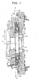
- FIG. 1 is a longitudinal sectional view showing a cranking rotational force transmission mechanism of the first exemplary embodiment that is provided near a rear end 2a of a crankshaft 2 of an internal combustion engine for a vehicle.
- the rear end 2a of the crankshaft 2 is the end of the crankshaft 2 on the side from which the rotational drive power of the internal combustion engine is output to a clutch or a torque converter.
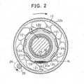
- FIG. 2 is a cross-sectional view of the crankshaft 2 that is taken along the perpendicular plane II - II indicated in FIG 1 , as seen from the left side of FIG. 1 , i.e., from the front side of the internal combustion engine.
- a journal bearing is formed by a cylinder block 4 and a ladder beam 6.
- the crankshaft 2 is rotatably supported by the cylinder block 4 via a journal 2b.
- the crankshaft 2 is arranged such that the rear end 2a of the crankshaft 2 protrudes from the lower rear portion of the cylinder block 4.
- a ring gear 12 is provided on the peripheral surface of a large-diameter portion 8 formed at the rear end 2a of the crankshaft 2 with a rolling bearing, which is a ball bearing 10 in this exemplary embodiment, being interposed therebetween.
- An outer race member 14 and a flywheel (or a drive plate) 16 are fixed on the rear surface of the large-diameter portion 8 of the crankshaft 2 using bolts 18.
- the outer race member 14 and the flywheel 16 rotate together with the crankshaft 2.
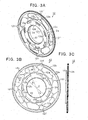
- the ring gear 12 is a circular disk having a large opening at the center thereof and a bending portion 12a that radially bends at a right angle along the entire periphery.
- FIG. 3A is a perspective view showing the front side of the ring gear 12
- FIG. 3B is a front view of the ring gear 12
- FIG. 3C is a right side view of the ring gear 12
- FIG. 4A is a perspective view showing the rear side of the ring gear 12
- FIG. 4B is a rear view of the ring gear 12
- FIG. 4C is a left side view of the ring gear 12.
- An inner race 22 for a one-way clutch 20 is formed like a flange at the inner peripheral edge of the ring gear 12.
- a gear portion 12b is formed like a ring at the outer periphery of the ring gear 12.
- the ring gear 12 is disposed, via the ball bearing 10 described above, on the outer periphery of the large-diameter portion 8 of the crankshaft 2 so as to be located on the opposite side of the one-way clutch 20, i.e., so as to be closer to the center side (i.e., the axis C side) than the one-way clutch 20 is.
- the ball bearing 10 is attached onto the outer periphery of the large-diameter portion 8 of the crankshaft 2 by press-fitting, and the inner race 22 is fitted to the outer periphery of the ball bearing 10.
- the ring gear 12 can freely rotate independently of the rotation of the crankshaft 2.
- the gear portion 12b of the ring gear 12 is constantly in mesh with a pinion gear 28 that is provided at a position lower than the crankshaft 2 and is rotated by the a starter motor 26. That is, when cranking the internal combustion engine, the ring gear 12 is rotated by the rotational force of the starter motor 26 transmitted via the pinion gear 28.
- Lubricant-return holes 12d are formed at an intermediate portion 12C between the inner race 22 and the bending portion 12a, which appears like a flat ring, so as to be located in a circle around the axis C at the same phase intervals.
- Each lubricant-return hole 12d penetrates the intermediate portion 12c from one side to the other side.
- the intermediate portion 12c can be regarded as "a portion of the ring gear between a portion of the ring gear at which the one-way clutch is provided and a portion of the ring gear at which the sealing member is provided" as recited in the invention.
- the number of the lubricant-return holes 12d is seven, and all the lubricant-return holes 12d are formed in the same shape. As shown in FIG. 3B , the lubricant-return holes 12d are shaped and positioned such that any lubricant-return hole 12d is not present in the region of the intermediate portion 12c that is point-symmetrical about the axis C to a phase region ⁇ occupied by other lubricant-return hole 12d.
- Seven openings 12f are formed at an outer periphery portion 12e of the ring gear 12, which connects the bending portion 12a and the gear portion 12b. Between any two adjacent openings 12f is formed a spoke 12g. Having such a spoke portion comprised of the openings 12f and the spokes 12g, the ring gear 12 is made light in weight.
- the relative phase positions of the openings 12f and the lubricant-return holes 12d are such that each lubricant-return hole 12d and each spoke 12g are located in line with each other in the radial direction of the ring gear 12 and the width of each lubricant-return hole 12d is smaller than the width of the radially inner end of each spoke 12g, as shown in FIG. 3B .
- phase position of each lubricant-return hole 12d and the phase position of the maximum width region M of each opening 12f, across which the dimension D of the opening 12f in the radial direction of the ring gear 12 is maximum, do not overlap with each other.
- the outer race member 14 is a circular disk having an opening 14a formed at the center thereof and an outer race 30 for the one-way clutch 20 which is formed at the outermost periphery so as to protrude perpendicularly therefrom.
- Multiple bolt holes 14b which are through holes into which bolts are inserted when bolting the outer race member 14 to the large-diameter portion 8 of the crankshaft 2, are formed in a circle around the opening 14a. In this exemplary embodiment, the number of the bolt holes 14b is eight.
- FIG. 5A is a front view of the outer race member 14
- FIG. 5B is a rear view of the outer race member 14
- FIG. 5C is a right side view of the outer race member 14
- FIG. 5D is a perspective view showing the front side of the outer race member 14
- FIG. 5E is a perspective view showing the rear side of the outer race member 14.
- the outer race member 14 is arranged relative to the ring gear 12 such that the outer race 30 radially faces the inner race 22 of the ring gear 12, as shown in FIG. 1 .
- a cage 20b having a sprag 20a is put on the inner race 22 of the ring gear 12 when or before putting the outer race 30 in position, so that the sprag 20a is sandwiched between the inner race 22 and the outer race 30. This is how the one-way clutch 20 is assembled.
- the one-way clutch 20 engages the outer race member 14 and the ring gear 12 when the ring gear 12 is rotating in the direction to transmit the torque from the starter motor 26 to the outer race member 14 (the clockwise direction indicated by the arrow in FIG. 2 ), thus enabling the crankshaft 2 to be rotated by the starter motor 26. Then, when the rotation speed of the outer race member 14 rotating together with the crankshaft 2 exceeds the rotation speed of the ring gear 12 being rotated by the starter motor 26 after the internal combustion engine starts running on its own, the rotation of the ring gear 12 relative to the outer race member 14 becomes reverse rotation. Thus, the one-way clutch 20 is released. As such, although the pinion gear 28 and the ring gear 12 are constantly in mesh with each other, the starter motor 26 may be turned off after starting the internal combustion engine.
- lubricant Oj is supplied through a lubricant passage 4a in the cylinder block 4, as indicated by the arrow in FIG. 1 , and the lubricant Oj is then injected towards the ball bearing 10.
- lubricant Or is supplied to the slide surfaces of the journal 2b of the crankshaft 2 via lubricant passages in the cylinder block 4 and the crankshaft 2. Part of the lubricant Or flows to the ball bearing 10 side.
- the lubricants Oj, Or that have flown to the ball bearing 10 then pass through the inside of the ball bearing 10 and flow into the one-way clutch 20.
- a first oil sealing member 32 and a second oil sealing member 34 which are ring-shaped sealing members, are provided to prevent the lubricants Oj, Or from leaking to the outside.
- the first oil sealing member 32 is interposed between the outer race 30 of the outer race member 14 and the bending portion 12a of the ring gear 12.
- the first oil sealing member 32 is fixed to the ring gear 12 by being fitted to the internal peripheral side of the bending portion 12a, so that a seal rip 32a that is formed at the internal periphery of the first oil sealing member 32 is slidably in contact with a sealed slide surface 30a that is the outer peripheral surface of the outer race 30, forming a slide-contact portion. Being thus arranged, the first oil sealing member 32 oil-seals between the outer race member 14 and the ring gear 12.
- the second oil sealing member 34 is provided on the side of the bending portion 12a that is opposite to where the first oil sealing member 32 is provided (i.e., the radially outer side of the first oil sealing member 32).
- the second oil sealing member 34 is fixed at the position shown in the drawings by the portion of the second oil sealing member 34 above the crankshaft 2 being fitted mainly to the internal peripheral side of an arc-shaped seal fitting portion 4b of the cylinder block 4 and by the portion of the second oil sealing member 34 below the crankshaft 2 being fitted mainly to the internal peripheral side of an arc-shaped seal fitting portion 36a that is provided at the rear end of an oil pan 36, so that the seal rip 32a formed at the internal periphery of the second oil sealing member 34 is slidably in contact with the outer peripheral surface of the bending portion 12a.
- the second oil sealing member 34 oil-seals between the ring gear 12 and the internal combustion engine (i.e., the cylinder block 4 and the oil pan 36).
- the starter motor 26 rotates the ring gear 12, and after the internal combustion engine starts running on its own, the ring gear 12 stops rotating due to the slippage at the one-way clutch 20.
- the lubricants Oj Or, as described above, pass through the inside of the ball bearing 10 and reach the rotating outer race member 14.
- the space 12f is oil-sealed from the outside by the first oil sealing member 32 fixed on the bending portion 12a.
- the lubricant-return holes 12d are formed so as to penetrate the intermediate portion 12c from one side to the other side thereof, as described above. Therefore, in the state where the ring gear 12 is stopped at the rotational phase position indicated in FIG. 2 , one of the lubricant-return holes 12d is located at the lowest position, and the lubricant in the space 12f returns to the oil pan 36 side via that lubricant-return hole 12d, as indicated by the arrow F3 in FIG 6 .
- the level of the lubricant surface Of in the stagnation region OS remains substantially constant at a level slightly below a lowest position level RL of the sealed slide surface 30a of the outer race 30 (i.e., the horizontal line that is tangent to the lower side of the outer periphery of the outer race member 14).
- FIG 7 and FIG. 8 each show an example in which the ring gear 12 is stopped at a different rotational phase position.
- the positions, the number, and the shapes of the lubricant-return holes 12d are determined such that at least a part of one of the lubricant-return hole 12d is present below the lowest position level RL at any rotational phase of the ring gear 12.
- the level of the lubricant surface Of in the stagnation region OS depends upon the state of the single lubricant-return hole 12d that is present at the lowest position, as in the example shown in FIG. 2 .
- the position of that lubricant-return hole 12d, through which the lubricant returns to the oil pan 36 side is slightly above the position of the lowest lubricant-return hole 12d in the example shown in FIG. 2 .
- the lubricant surface Of remains substantially constant at a position slightly above the position at which the lubricant surface Of remains substantially constant in the example shown in FIG. 2 .
- the lubricant surface is at the same level as the lowest position level RL.
- the area of the portion of the lubricant-return hole 12d that is present below the lowest position level RL, when the internal combustion engine is running in a steady manner, is determined, so that the level of the lubricant surface Of substantially matches the lowest position level RL.
- any portion of the outer race 30 is not soaked deeply into the lubricant. That is, the lubricant is not heavily agitated by the components or portions that are rotating on the radially inner side with respect to the outer race 30.
- the slide-contact portion between the seal rip 32a of the first oil sealing member 32 and the sealed slide surface 30a of the outer race 30 is located in the position which the lubricant is brought into contact with as the lubricant surface Of waves, even in the state where the level of the lubricant surface Of is as low as shown in FIG. 2 .
- the lubricant may not be brought into contact with the slide-contact portion even when the lubricant surface Of is waving.
- an inner peripheral end 12i of each lubricant-return hole 12d is located near the outer race 30 as shown in FIG. 2 , the lubricant flows through the narrow gap between the outer race 30 and the intermediate portion 12c of the ring gear 12, as indicated by the arrow F2 in FIG. 6 , and the lubricant is then splashed into the space 12h from the narrow gap. Since the point from which the lubricant is splashed is located at the same level and thus is very close to the slide-contact portion, the lubricant reaches the slide-contact portion in the form of droplets.
- the positions, the number, and the shapes of the lubricant-return holes 12d which serve to adjust the level of the lubricant surface Of as described above, are determined such that a flow rate V2 at the lubricant passage indicated by the arrow F2 in FIG. 6 when the internal combustion engine is running in a steady manner is equal to a flow rate V3 at the lubricant passage indicated by the arrow F3 in FIG. 6 when the lubricant surface. Of in the space 12h is substantially at the lowest position level RL of the sealed slide surface 30a.
- each lubricant-return hole 12d may be formed such that a sectional area of the lubricant passage in the lubricant-return hole 12d is obtained when the ring gear 12 is stopped at a typical rotational phase, e.g., at the rotational phase shown in FIG. 7 .
- each lubricant-return hole 12d may be formed such that the lubricant surface Of is substantially aligned with the lowest position level RL in the state where the sectional area of the lubricant passage in the lubricant-return hole 12d is minimum, such as when the ring gear 12 is at the rotational phase shown in FIG. 8 .
- the relation between the sectional area A1 of the lubricant passage that is indicated by the arrow F1 in FIG. 6 and is located upstream of the one-way clutch 20 and the sectional area A2 of the lubricant passage that is indicated by the arrow F2 in FIG. 6 and is located downstream of the one-way clutch 20 is A1 ⁇ A2.
- the relation between the flow rate V1 at the lubricant passage indicated by the arrow F1 and the flow rate V2 at the lubricant passage indicated by the arrow F2 can be maintained to be V1 ⁇ V2 in a wide operation range of the internal combustion engine.
- the relation between the sectional area A2 of the lubricant passage downstream of the one-way clutch 20 and the sectional area A3 of the lubricant passage in the lubricant-return hole 12d, which is indicated by the arrow F3 in FIG. 6 , is A2 ⁇ A3 at any rotational phase of the ring gear 12.
- the relation between the flow rate V2 at the lubricant passage indicated by the arrow F2 and the flow rate V3 at the lubricant passage indicated by the arrow F3 can be maintained to be V2 ⁇ V3 in a wide operation range of the internal combustion engine.
- the relation between the sectional areas of the lubricant passages in the respective gaps and lubricant-return holes 12d is set to be A1 ⁇ A2 ⁇ A3, so that the relation between the flow rates V1, V2, V3 can be maintained to be V1 ⁇ V2 ⁇ V3 in a wide operation range of the internal combustion engine.
- the lubricant does not stagnate in the space 12h above the first oil sealing member 32, and therefore bubbling of lubricant and production of sludge, which may otherwise be caused by agitation of the lubricant surface in the space 12h, can be prevented.
- the lubricant is splashed into the space 12h from the narrow gap between the outer race 30 and the intermediate portion 12c of the ring gear 12, which is indicated by the arrow F2 in FIG. 6 .
- the lubricant reaches, in the form of droplets, the slide-contact portion between the seal rip 32a of the first oil sealing member 32 and the sealed slide surface 30a of the outer race 30, so that the slide-contact portion is lubricated and cooled.
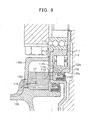
- the sectional area of each lubricant-return hole 112d of the ring gear 112 is so large that the lubricant-return hole 112d does not serve to adjust the level of the lubricant surface Of in the space 122h above the first oil sealing member 132. Instead, the adjustment of the level of the lubricant surface Of is accomplished by the position (i.e., the sectional area A1) and shape (i.e., the height H) of a lubricant outlet hole 136c that is formed in a wall 136b of the oil pan 136 so as to face the lubricant-return hole 112d.
- the lubricant outlet hole 136c is positioned and shaped such that a flow rate V14 at the lubricant passage indicated by the arrow F14 in FIG. 9 and a flow rate V15 at the lubricant passage indicated by the arrow F15 in FIG. 9 are equal with each other in the state where the level of the lubricant surface Of is lower than the sealed slide surface 130a of the outer race 130 when the internal combustion engine is running in a steady manner.
- the lubricant outlet hole 136c is positioned and shaped such that, when the internal combustion engine is running in a steady state, the level of the lubricant surface Of of lubricant stagnating between the ring gear 112 and the outer race member 114 does not exceed the horizontal line that is tangent to the lower side of the sealed slide surface 130a of the outer race 130.
- FIG. 9 shows the state in which the lubricant surface Of and the horizontal line are at the same level.
- the flow rate V14 at the lubricant passage indicated by the arrow F14 is equal to the sum of the flow rate V12 at the lubricant passage indicated by the arrow F12 (or F11) and the flow rate V13 at the lubricant passage indicated by the arrow F13.
- the sectional area A15 of the lubricant outlet hole 136c and the height H from the lubricant outlet hole 136c to the sealed slide surface 130a are set such that the relation among the flow rate V14, the sectional area A 15, the height H, and the flow rate coefficient Cf of the lubricant satisfies Inequality (1) shown below.
- V ⁇ 14 ⁇ Cf ⁇ A ⁇ 15 ⁇ 2 ⁇ g H where is an operator indicating the square root of the value in the parentheses and g represents the gravitational acceleration.
- the right side of Inequality (1) represents the amount of lubricant that is discharged via the lubricant outlet hole 136c per unit time, i.e., the flow rate V15.
- the lubricant reaches, in the form of droplets, the slide-contact portion between the seal rip 132a of the first oil sealing member 132 and the sealed slide surface 130a of the outer race 130, so that the slide-contact portion is lubricated and cooled.
- the lubricant-return holes are provided at the same phase intervals in each of the exemplary embodiments described above, the lubricant-return holes may not be provided at the same phase intervals. That is, even if the lubricant-return holes are not provided at the same phase intervals, the advantageous effect (4) that has been descried above in connection with the first exemplary embodiment can be obtained by arranging the positions of the respective lubricant-return holes such that any lubricant-return hole is not located at a position that is point-symmetrical to another lubricant-return hole about the center of the ring gear.
- forming an odd number of lubricant-return holes at the same phase intervals in the intermediate portion of the ring gear provides an arrangement of the lubricant-return holes in which any lubricant-return hole is not located at a position that is point-symmetrical to another lubricant-return hole about the center of the ring gear.
- Such an arrangement of the lubricant-return holes can be obtained also by forming an even number of lubricant-return holes at uneven intervals such that any lubricant-return hole is not located at a position that is point-symmetrical to another lubricant-return hole about the center of the ring gear.
- the advantageous effect (5) that has been described above in connection with the first exemplary embodiment can be obtained by arranging the positions of the lubricant-return holes and the positions of the openings of the spoke portion such that the phase position of each lubricant-return hole does not overlap the phase position of the portion of each opening in the spoke portion at which the radial dimension of the same opening is maximum.
- the level of the lubricant surface Of is substantially aligned with the horizontal line tangent to the lower side of the sealed slide surface (i.e., the lowest position level RL) in the first exemplary embodiment, if lubrication and cooling of the first oil sealing member are not directly performed by the lubricant surface Of, the level of the lubricant surface Of may be set below the lowest position level RL.
- the level of the lubricant surface Of may be set below the lowest position level RL in a structure in which the lubricant is splashed from the narrow gap between the outer race and the intermediate portion of the ring gear (i.e., the gap indicated by the arrow F2, the gap indicated by the arrow F12) so that the lubricant reaches, in the form of droplets, the seal rip of the first oil sealing member and the sealed slide surface of the outer race, as in the second and third exemplary embodiments.
- the outer periphery of the outer race member is the outer race of the one-way clutch in each of the exemplary embodiments described above, if there is any part or portion that protrudes outward from the outer periphery of the outer race member, the structures in the respective exemplary embodiments may be designed by using the horizontal line that is tangent to the protruding part or portion as the lowest position level RL. Nevertheless, if the structural elements of the outer race member that are present on the radially inner side of the outer race are significantly responsible for agitation of the lubrication surface Of, the lubricant surface Os may be set with respect to the outer peripheral surface of the outer race, as it is in the respective exemplary embodiments described above.
- the outer race member may be provided as a part of the flywheel (or the drive plate), rather than as an independent member, That is, the flywheel (or the drive plate) and the outer race member may be provided as a single component by forming a portion of the flywheel (or the drive plate) as an outer race.
- the flywheel (or the drive plate) corresponds to the outer race member.
Landscapes
- Engineering & Computer Science (AREA)
- General Engineering & Computer Science (AREA)
- Mechanical Engineering (AREA)
- Chemical & Material Sciences (AREA)
- Combustion & Propulsion (AREA)
- Lubrication Of Internal Combustion Engines (AREA)
- General Details Of Gearings (AREA)
Claims (10)
- Structure de lubrification d'un mécanisme de transmission de force de rotation de démarrage pour un moteur à combustion interne, le mécanisme de transmission de force de rotation de démarrage comportant un organe formant bague extérieure (14 ; 114) qui est accouplé à un arbre de sortie tournant (2) du moteur à combustion interne ; une couronne dentée (12 ; 112) à laquelle est transmise une force d'entraînement en rotation depuis un démarreur (26) et dont une partie fait face à l'organe formant bague extérieure depuis le côté du moteur à combustion interne ; et un embrayage unidirectionnel (20) qui est placé à un endroit au niveau duquel la partie de la couronne dentée fait face à l'organe formant bague extérieure et qui transmet une force de rotation du démarreur dans une direction de rotation de la couronne dentée à l'organe formant bague extérieure et interrompt la transmission d'une force de rotation du démarreur dans l'autre direction de rotation de la couronne dentée à l'organe formant bague extérieure, la structure de lubrification étant caractérisée en ce que :un organe d'étanchéité (32 ; 132) est prévu pour assurer l'étanchéité à l'huile d'un espace entre la couronne dentée et l'organe formant bague extérieure de telle sorte que l'embrayage unidirectionnel se trouve dans une zone étanche à l'huile dans le côté du moteur à combustion interne ;un trou de retour de lubrifiant (12d ; 112d) est formé dans une partie de la couronne dentée entre une partie de la couronne dentée au niveau de laquelle se trouve l'embrayage unidirectionnel et une partie de la couronne dentée au niveau de laquelle se trouve l'organe d'étanchéité, le trou de retour de lubrifiant pénétrant dans la couronne dentée depuis un côté jusqu'à l'autre côté ; etune pluralité de trous de retour de lubrifiant étant prévue et les trous de retour de lubrifiant étant formés autour d'un axe de rotation de la couronne dentée, de telle sorte que, lors de toute phase de rotation de la couronne dentée, au moins une partie de l'un des trous de retour de lubrifiant soit située sous une ligne horizontale qui est tracée tangentiellement par rapport à un côté inférieur d'une périphérie extérieure de l'organe formant bague extérieure.
- Structure de lubrification selon la revendication 1, dans laquelle
une pluralité de trous de retour de lubrifiant est prévue et les trous de retour de lubrifiant sont formés autour d'un axe de rotation de la couronne dentée, de telle sorte que, lors de toute phase de rotation de la couronne dentée, au moins une partie de l'un des trous de retour de lubrifiant soit située sous une ligne horizontale qui est tracée tangentiellement par rapport à un côté inférieur d'une périphérie extérieure d'une bague extérieure (30 ; 130) de l'embrayage unidirectionnel. - Structure de lubrification selon la revendication 1 ou 2, dans laquelle
une partie périphérique la plus à l'extérieur de l'organe formant bague extérieure forme une bague extérieure de l'embrayage unidirectionnel, et
une extrémité périphérique intérieure de chacun des trous de retour de lubrifiant est radialement proche de la bague extérieure de l'embrayage unidirectionnel. - Structure de lubrification selon l'une quelconque des revendications 1 à 3, dans laquelle
au moins un paramètre parmi la position de chacun des trous de retour de lubrifiant, le nombre de trous de retour de lubrifiant et la forme de chacun des trous de retour de lubrifiant est défini de telle sorte que, lorsque le moteur à combustion interne tourne à une cadence stable, le niveau d'une surface du lubrifiant est plus bas qu'un niveau qui est essentiellement aligné avec une ligne horizontale qui est tracée tangentiellement par rapport à un côté inférieur de la périphérie extérieure de l'organe formant bague extérieure. - Structure de lubrification selon l'une quelconque des revendications 1 à 3, dans laquelle
l'organe d'étanchéité est en contact à coulissement avec la périphérie extérieure d'une bague extérieure de l'embrayage unidirectionnel depuis le côté radialement extérieur de la bague extérieure, la bague extérieure étant formée avec l'organe formant bague extérieure, et
au moins un paramètre parmi la position de chacun des trous de retour de lubrifiant, le nombre de trous de retour de lubrifiant et la forme de chacun des trous de retour de lubrifiant est défini de telle sorte que, lorsque le moteur à combustion interne tourne à une cadence stable, le niveau d'une surface du lubrifiant est essentiellement aligné avec une ligne horizontale qui est tracée tangentiellement par rapport au côté inférieur d'une partie de contact à coulissement entre la bague extérieure et l'organe d'étanchéité. - Structure de lubrification d'un mécanisme de transmission de force de rotation de démarrage selon la revendication 1, dans laquelle les trous de retour de lubrifiant sont formés de telle sorte que les trous de toute paire de trous de retour de lubrifiant ne se trouvent respectivement pas dans des positions de phase qui se correspondent par symétrie centrale autour du centre de la couronne dentée.
- Structure de lubrification d'un mécanisme de transmission de force de rotation de démarrage selon la revendication 1, dans laquelle
la couronne dentée comporte une partie à rayons qui est située sur le côté radialement extérieur de l'organe d'étanchéité et dans laquelle se trouvent, de manière alternée, des rayons et des ouvertures dans la direction périphérique de la couronne dentée, et
les positions de phase des trous de retour de lubrifiant sont disposées de façon à ne pas chevaucher les positions de phase au niveau desquelles les dimensions radiales des ouvertures sont maximales. - Structure de lubrification selon l'une quelconque des revendications 1 à 7, dans laquelle
une aire en section A1 d'un passage de lubrifiant en amont de l'embrayage unidirectionnel, une aire en section A2 d'un passage de lubrifiant en aval de l'embrayage unidirectionnel et une aire en section A3 d'un passage de lubrifiant dans le trou de retour de lubrifiant sont définies de telle sorte que A1 ≤ A2 ≤ A3 soit vérifié lors de toute phase de rotation de la couronne dentée. - Structure de lubrification selon l'une quelconque des revendications 1 à 8, comprenant en outre une paroi (136b) qui se trouve sur le côté d'un carter d'huile (136) du moteur à combustion interne, la paroi comportant un trou de sortie de lubrifiant (136c) formé dans celle-ci, le lubrifiant qui a été ramené par les trous de retour de lubrifiant tombant du côté d'un réservoir de lubrifiant du carter d'huile à travers le trou de sortie de lubrifiant,
le trou de sortie de lubrifiant présentant une forme et étant positionné de telle sorte que, lorsque le moteur à combustion interne tourne à une cadence stable, le niveau d'une surface du lubrifiant stagnant entre la couronne dentée et l'organe formant bague extérieure ne dépasse pas une ligne horizontale qui est tracée tangentiellement par rapport au côté inférieur de la périphérie extérieure de l'organe formant bague extérieure. - Structure de lubrification selon la revendication 9, dans laquelle
V14≤Cf·A15√(2gH) est vérifié, où V14 est un débit du lubrifiant s'écoulant vers le trou de sortie de lubrifiant, A15 est l'aire en section d'un passage de lubrifiant dans le trou de sortie de lubrifiant, H est la hauteur du trou de sortie de lubrifiant jusqu'à une surface de coulissement étanche de l'organe d'étanchéité au niveau de laquelle l'organe d'étanchéité vient en contact à coulissement avec l'organe formant bague extérieure, g est l'accélération de la pesanteur et Cf est un coefficient de débit du lubrifiant.
Applications Claiming Priority (2)
| Application Number | Priority Date | Filing Date | Title |
|---|---|---|---|
| JP2006072896A JP4462213B2 (ja) | 2006-03-16 | 2006-03-16 | 内燃機関始動回転力伝達機構潤滑構造 |
| PCT/IB2007/001500 WO2007105109A2 (fr) | 2006-03-16 | 2007-03-15 | Structure de lubrification de mecanisme de transmission a force de rotation de demarrage pour moteur a combustion interne |
Publications (2)
| Publication Number | Publication Date |
|---|---|
| EP1994276A2 EP1994276A2 (fr) | 2008-11-26 |
| EP1994276B1 true EP1994276B1 (fr) | 2015-05-06 |
Family
ID=38509857
Family Applications (1)
| Application Number | Title | Priority Date | Filing Date |
|---|---|---|---|
| EP20070734778 Ceased EP1994276B1 (fr) | 2006-03-16 | 2007-03-15 | Structure de lubrification de mecanisme de transmission a force de rotation de demarrage pour moteur a combustion interne |
Country Status (6)
| Country | Link |
|---|---|
| US (2) | US8267060B2 (fr) |
| EP (1) | EP1994276B1 (fr) |
| JP (1) | JP4462213B2 (fr) |
| KR (1) | KR100995788B1 (fr) |
| CN (1) | CN101400888B (fr) |
| WO (1) | WO2007105109A2 (fr) |
Families Citing this family (12)
| Publication number | Priority date | Publication date | Assignee | Title |
|---|---|---|---|---|
| JP4211767B2 (ja) | 2005-07-29 | 2009-01-21 | トヨタ自動車株式会社 | 内燃機関始動装置のオイル阻止構造 |
| JP4179349B2 (ja) | 2006-06-23 | 2008-11-12 | トヨタ自動車株式会社 | リングギヤ、内燃機関始動回転力伝達機構及びリングギヤ製造方法 |
| US20120125280A1 (en) | 2009-08-27 | 2012-05-24 | Toyota Jidosha Kabushiki Kaisha | Starting torque transmission mechanism for internal combustion engine |
| WO2011060551A1 (fr) * | 2009-11-19 | 2011-05-26 | Magna Powertrain Inc. | Embrayage unidirectionnel avec amortisseur de vibrations pour un système de démarrage de moteur |
| EP2515011A4 (fr) * | 2009-12-15 | 2016-04-13 | Toyota Motor Co Ltd | Structure de joint à huile |
| JP5425696B2 (ja) * | 2010-04-19 | 2014-02-26 | Nskワーナー株式会社 | ワンウェイクラッチを用いたエンジンスタータ機構 |
| JP5363422B2 (ja) * | 2010-06-01 | 2013-12-11 | トヨタ自動車株式会社 | 車両用スタータリングギヤ |
| BRMU9100610U2 (pt) * | 2011-03-18 | 2014-03-25 | Zen S A Ind Metalurgica | Disposição aplicada em unidade de partida que trabalha constantemente engrenada ao motor principal |
| CN102251853B (zh) * | 2011-06-27 | 2012-11-07 | 重庆长安汽车股份有限公司 | 一种汽车动力系统用发动机与电机集成结构 |
| US10072627B2 (en) * | 2011-11-07 | 2018-09-11 | Magna Powertrain Inc. | Torque transfer unit for an engine starting system |
| EP2824318A1 (fr) * | 2013-07-09 | 2015-01-14 | Aktiebolaget SKF | Mécanisme de transmission de couple |
| EP2824349A1 (fr) * | 2013-07-09 | 2015-01-14 | Aktiebolaget SKF | Procédé de fabrication d'un mécanisme de transmission de couple |
Family Cites Families (17)
| Publication number | Priority date | Publication date | Assignee | Title |
|---|---|---|---|---|
| DE409374C (de) * | 1923-08-14 | 1925-02-05 | Maybach Motorenbau G M B H | Freilaufkupplung, insbesondere fuer Anlassgetriebe von Kraftfahrzeugen |
| US4103564A (en) * | 1976-12-17 | 1978-08-01 | Caterpillar Tractor Co. | Limited slip differential |
| DE69404782T2 (de) * | 1993-08-30 | 1997-12-04 | Honda Motor Co Ltd | Ölzufuhrkonstruktion für Anlassräder in einer Brennkraftmaschine |
| JP3293971B2 (ja) | 1993-08-30 | 2002-06-17 | 本田技研工業株式会社 | 内燃機関の始動用ドリブンギア軸受給油構造 |
| JPH10122107A (ja) | 1996-10-22 | 1998-05-12 | Kawasaki Heavy Ind Ltd | エンジンのスタータ装置 |
| JP4273198B2 (ja) | 1999-03-25 | 2009-06-03 | 三菱自動車工業株式会社 | 内燃機関の始動装置 |
| JP2003083216A (ja) | 2001-09-06 | 2003-03-19 | Moric Co Ltd | エンジンのスタータ構造 |
| DE10343400A1 (de) | 2003-09-19 | 2005-04-14 | Daimlerchrysler Ag | Kraftfahrzeugantrieb mit Starter-Anlage |
| RU2346996C2 (ru) | 2004-06-29 | 2009-02-20 | ЮРОПИЭН НИКЕЛЬ ПиЭлСи | Усовершенствованное выщелачивание основных металлов |
| WO2006016668A1 (fr) | 2004-08-09 | 2006-02-16 | Toyota Jidosha Kabushiki Kaisha | Dispositif de démarrage |
| JP2006057612A (ja) | 2004-08-24 | 2006-03-02 | Toyota Motor Corp | 始動装置、自動停止制御装置方法、及びその方法 |
| JP2006063913A (ja) | 2004-08-27 | 2006-03-09 | Toyota Motor Corp | 始動装置及びその駆動制御方法 |
| JP4211767B2 (ja) * | 2005-07-29 | 2009-01-21 | トヨタ自動車株式会社 | 内燃機関始動装置のオイル阻止構造 |
| JP4449852B2 (ja) * | 2005-07-29 | 2010-04-14 | トヨタ自動車株式会社 | 内燃機関始動回転力伝達機構 |
| US7485066B2 (en) * | 2005-08-10 | 2009-02-03 | Luk Lamellen Und Kupplungsbau Beteiligungs Kg | Geared torque converter with multi-plate clutches and planetary gearset |
| JP4127289B2 (ja) * | 2006-04-21 | 2008-07-30 | トヨタ自動車株式会社 | 内燃機関の始動装置 |
| JP4179349B2 (ja) * | 2006-06-23 | 2008-11-12 | トヨタ自動車株式会社 | リングギヤ、内燃機関始動回転力伝達機構及びリングギヤ製造方法 |
-
2006
- 2006-03-16 JP JP2006072896A patent/JP4462213B2/ja not_active Expired - Fee Related
-
2007
- 2007-03-15 KR KR1020087022609A patent/KR100995788B1/ko not_active Expired - Fee Related
- 2007-03-15 US US12/224,623 patent/US8267060B2/en not_active Expired - Fee Related
- 2007-03-15 CN CN2007800092209A patent/CN101400888B/zh not_active Expired - Fee Related
- 2007-03-15 EP EP20070734778 patent/EP1994276B1/fr not_active Ceased
- 2007-03-15 WO PCT/IB2007/001500 patent/WO2007105109A2/fr not_active Ceased
-
2012
- 2012-08-10 US US13/572,304 patent/US8434448B2/en not_active Expired - Fee Related
Also Published As
| Publication number | Publication date |
|---|---|
| JP2007247561A (ja) | 2007-09-27 |
| KR100995788B1 (ko) | 2010-11-22 |
| KR20080094835A (ko) | 2008-10-24 |
| WO2007105109A3 (fr) | 2007-12-13 |
| US8434448B2 (en) | 2013-05-07 |
| JP4462213B2 (ja) | 2010-05-12 |
| CN101400888A (zh) | 2009-04-01 |
| US8267060B2 (en) | 2012-09-18 |
| US20120325177A1 (en) | 2012-12-27 |
| CN101400888B (zh) | 2010-09-22 |
| WO2007105109A2 (fr) | 2007-09-20 |
| EP1994276A2 (fr) | 2008-11-26 |
| US20090008190A1 (en) | 2009-01-08 |
Similar Documents
| Publication | Publication Date | Title |
|---|---|---|
| EP1994276B1 (fr) | Structure de lubrification de mecanisme de transmission a force de rotation de demarrage pour moteur a combustion interne | |
| US7370741B2 (en) | Engine start roller clutch-housed type rotation transmission device | |
| EP1813839A2 (fr) | Lubrification positive d'un engrenage moteur | |
| US6010420A (en) | Pulley, ball bearing and fan for preventing the occurence of abnormal noise under cold ambient conditions | |
| US6491438B1 (en) | Main bearing for engine | |
| JP6295727B2 (ja) | 円すいころ軸受 | |
| JPH0650115B2 (ja) | 回転送風機 | |
| US20100151983A1 (en) | Spider-less vehicle differential | |
| CN106015534B (zh) | 差动装置 | |
| US20150148174A1 (en) | Electric vehicle transaxle | |
| US20110265756A1 (en) | Cylinder head | |
| JP3925145B2 (ja) | 回転軸の軸受け潤滑構造 | |
| JP4590004B1 (ja) | エンジン始動用動力伝達装置 | |
| US6793052B2 (en) | Torque converter | |
| US9816582B2 (en) | Balancer device for internal combustion engine | |
| JP3625139B2 (ja) | 自動変速機の潤滑構造 | |
| JP7466501B2 (ja) | 円すいころ軸受 | |
| EP2159454A1 (fr) | Engrenage baladeur et moyeu dotés d'un revêtement | |
| JP4840491B2 (ja) | 内燃機関始動回転力伝達機構潤滑構造 | |
| RU2382262C2 (ru) | Механизм трансмиссии | |
| US20040129097A1 (en) | Starting apparatus for an engine | |
| JP2007126999A (ja) | 内燃機関始動回転力伝達機構潤滑構造 | |
| JP2011174438A (ja) | 内燃機関始動回転力伝達機構 | |
| JP2020046051A (ja) | 潤滑構造 | |
| JP4609354B2 (ja) | 潤滑油供給システム |
Legal Events
| Date | Code | Title | Description |
|---|---|---|---|
| PUAI | Public reference made under article 153(3) epc to a published international application that has entered the european phase |
Free format text: ORIGINAL CODE: 0009012 |
|
| 17P | Request for examination filed |
Effective date: 20080912 |
|
| AK | Designated contracting states |
Kind code of ref document: A2 Designated state(s): CZ DE FR GB IT PL |
|
| DAX | Request for extension of the european patent (deleted) | ||
| RBV | Designated contracting states (corrected) |
Designated state(s): CZ DE FR GB IT PL |
|
| 17Q | First examination report despatched |
Effective date: 20100713 |
|
| RAP1 | Party data changed (applicant data changed or rights of an application transferred) |
Owner name: TOYOTA JIDOSHA KABUSHIKI KAISHA |
|
| GRAP | Despatch of communication of intention to grant a patent |
Free format text: ORIGINAL CODE: EPIDOSNIGR1 |
|
| INTG | Intention to grant announced |
Effective date: 20141120 |
|
| RIN1 | Information on inventor provided before grant (corrected) |
Inventor name: ASADA, TOSHIAKI Inventor name: ISHIKAWA, MAKOTO Inventor name: SHIBA, TOSHIMITSU Inventor name: SAKAI, KAZUHITO Inventor name: SUZUKI, TOMOAKI |
|
| GRAS | Grant fee paid |
Free format text: ORIGINAL CODE: EPIDOSNIGR3 |
|
| GRAA | (expected) grant |
Free format text: ORIGINAL CODE: 0009210 |
|
| AK | Designated contracting states |
Kind code of ref document: B1 Designated state(s): DE |
|
| RBV | Designated contracting states (corrected) |
Designated state(s): DE |
|
| REG | Reference to a national code |
Ref country code: DE Ref legal event code: R096 Ref document number: 602007041351 Country of ref document: DE Effective date: 20150618 |
|
| REG | Reference to a national code |
Ref country code: DE Ref legal event code: R084 Ref document number: 602007041351 Country of ref document: DE |
|
| REG | Reference to a national code |
Ref country code: DE Ref legal event code: R097 Ref document number: 602007041351 Country of ref document: DE |
|
| PLBE | No opposition filed within time limit |
Free format text: ORIGINAL CODE: 0009261 |
|
| STAA | Information on the status of an ep patent application or granted ep patent |
Free format text: STATUS: NO OPPOSITION FILED WITHIN TIME LIMIT |
|
| 26N | No opposition filed |
Effective date: 20160209 |
|
| PGFP | Annual fee paid to national office [announced via postgrant information from national office to epo] |
Ref country code: DE Payment date: 20190305 Year of fee payment: 13 |
|
| REG | Reference to a national code |
Ref country code: DE Ref legal event code: R119 Ref document number: 602007041351 Country of ref document: DE |
|
| PG25 | Lapsed in a contracting state [announced via postgrant information from national office to epo] |
Ref country code: DE Free format text: LAPSE BECAUSE OF NON-PAYMENT OF DUE FEES Effective date: 20201001 |