EP1813839A2 - Lubrification positive d'un engrenage moteur - Google Patents
Lubrification positive d'un engrenage moteur Download PDFInfo
- Publication number
- EP1813839A2 EP1813839A2 EP07101304A EP07101304A EP1813839A2 EP 1813839 A2 EP1813839 A2 EP 1813839A2 EP 07101304 A EP07101304 A EP 07101304A EP 07101304 A EP07101304 A EP 07101304A EP 1813839 A2 EP1813839 A2 EP 1813839A2
- Authority
- EP
- European Patent Office
- Prior art keywords
- lubricant
- teeth
- fluidic
- shaft
- source
- Prior art date
- Legal status (The legal status is an assumption and is not a legal conclusion. Google has not performed a legal analysis and makes no representation as to the accuracy of the status listed.)
- Withdrawn
Links
Images


Classifications
-
- F—MECHANICAL ENGINEERING; LIGHTING; HEATING; WEAPONS; BLASTING
- F16—ENGINEERING ELEMENTS AND UNITS; GENERAL MEASURES FOR PRODUCING AND MAINTAINING EFFECTIVE FUNCTIONING OF MACHINES OR INSTALLATIONS; THERMAL INSULATION IN GENERAL
- F16H—GEARING
- F16H57/00—General details of gearing
- F16H57/04—Features relating to lubrication or cooling or heating
- F16H57/042—Guidance of lubricant
- F16H57/0427—Guidance of lubricant on rotary parts, e.g. using baffles for collecting lubricant by centrifugal force
-
- F—MECHANICAL ENGINEERING; LIGHTING; HEATING; WEAPONS; BLASTING
- F16—ENGINEERING ELEMENTS AND UNITS; GENERAL MEASURES FOR PRODUCING AND MAINTAINING EFFECTIVE FUNCTIONING OF MACHINES OR INSTALLATIONS; THERMAL INSULATION IN GENERAL
- F16H—GEARING
- F16H57/00—General details of gearing
- F16H57/04—Features relating to lubrication or cooling or heating
- F16H57/042—Guidance of lubricant
- F16H57/043—Guidance of lubricant within rotary parts, e.g. axial channels or radial openings in shafts
- F16H57/0431—Means for guiding lubricant directly onto a tooth surface or to foot areas of a gear, e.g. by holes or grooves in a tooth flank
-
- F—MECHANICAL ENGINEERING; LIGHTING; HEATING; WEAPONS; BLASTING
- F16—ENGINEERING ELEMENTS AND UNITS; GENERAL MEASURES FOR PRODUCING AND MAINTAINING EFFECTIVE FUNCTIONING OF MACHINES OR INSTALLATIONS; THERMAL INSULATION IN GENERAL
- F16H—GEARING
- F16H57/00—General details of gearing
- F16H57/04—Features relating to lubrication or cooling or heating
- F16H57/048—Type of gearings to be lubricated, cooled or heated
- F16H57/0493—Gearings with spur or bevel gears
Definitions
- the present invention relates to the lubrication of gears. More particularly, the present invention relates to the lubrication of toothed meshing gears.
- the present invention provides a gear assembly, comprising: a shaft, a toothed wheel, a source of lubricant and a plurality of fluidic passages.
- the toothed wheel is mounted on the shaft and configured to rotate therewith.
- the toothed wheel has a plurality of teeth formed on, and extending radially from, a periphery thereof.
- Each of the plurality of teeth is defined by a root portion, an involute profile portion, and a minimal stress portion located between the root portion and the involute profile portion.
- the source of lubricant is adapted to supply a lubricant to the gear assembly, either through a bore in the shaft or from an external jet source.
- Each of the plurality of fluidic passages is in fluidic communication with the source of lubricant and the minimal stress portion of one of the plurality of teeth.
- lubricant flows, under the influence of centrifugal force, to the minimal stress portion of each of the plurality of teeth via the plurality of fluidic passages.
- a gear assembly comprising, a shaft, a toothed wheel, an annular well, and a plurality of fluidic passages.
- the toothed wheel is mounted on the shaft, and configured to rotate therewith.
- the toothed wheel includes a plurality of teeth formed on, and extending radially from, a periphery thereof.
- Each of the plurality of teeth is defined by a root portion, an involute profile portion, and a minimal stress portion located between the root portion and the involute profile portion.
- the annular well is formed in the gear assembly between the shaft and the plurality of teeth and adapted to receive a lubricant.
- Each of the plurality of fluidic passages is in fluidic communication with the annular well and the minimal stress portion of one of the plurality of teeth.
- lubricant flows, under the influence of centrifugal force, to the plurality of teeth via the fluidic passages.
- a method of lubricating a plurality of teeth in a meshing gear comprising the steps of providing a shaft, configured to rotate, and a toothed wheel mounted on the shaft.
- the toothed wheel also configured to rotate.
- the method further includes the steps of providing a source of lubricant to provide lubricant to the gear assembly, and forming a plurality of fluidic passages, each fluidic passage in fluidic communication with the lubricant and the minimal stress portion of one of the plurality of teeth.
- the toothed wheel is configured to rotate therewith the shaft and includes a plurality of teeth formed on, and extending radially from, a periphery thereof.
- Each of the plurality of teeth is defined by a root portion, an involute profile portion, and a minimal stress portion located between the root portion and the involute profile portion.
- lubricant flows, under the influence of centrifugal force, to the minimal stress portion of each of the plurality of teeth via the plurality of fluidic passages.
- FIG. 1 is a schematic representation of a cross-section of a meshing gear taken along line 1-1 of FIG. 2 according to the present invention
- FIG. 2 is a schematic representation of a cross-section of the meshing gear of FIG. 1 taken along line 2-2 of FIG. 1, according to the present invention
- FIG. 3 is a schematic representation of a cross-section of an alternate embodiment of a meshing gear taken along line 3-3 of FIG. 4, according to the present invention
- FIG. 4 is a schematic representation of a cross-section of the embodiment of FIG. 3 taken along line 4-4 of FIG. 3, according to the present invention
- FIG. 5 is a schematic representation of a cross-section of another alternate embodiment illustrating a modification to the embodiment shown in FIGs. 3 and 4, according to the present invention
- FIG. 6 is a schematic representation of a cross-section of another alternate embodiment illustrating a modification to the embodiment shown in FIGs. 3 and 4, according to the present invention
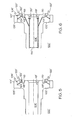
- FIG. 7 is a schematic representation of a cross-section of yet another alternate embodiment illustrating a modification to the meshing gear of FIGs. 3 and 4 taken along line 7-7 FIG. 8, according to the present invention.
- FIG. 8 is a schematic representation of a cross-section of the embodiment of FIG. 7 taken along line 8-8 of FIG. 7, according to the present invention.
- the present invention employs a means for applying a lubricant to the involute profile of a tooth on a meshing gear via a point of low stress in the tooth root of the gear.
- the device and method provide for the positive lubrication and maintenance of a lubricating film in meshing gears.
- FIGs. 1 and 2 illustrated is a portion of a gear 100, and more particularly a toothed wheel 102, mounted on a shaft 104, sometimes referred to as a gear assembly.
- the assembly may be one single piece of hardware, but is hereinafter referred to as an assembly.
- the shaft 104 is configured, upon receipt of a suitable drive force, to rotate.
- the shaft 104 may simply be a bore of the gear assembly.
- Toothed wheel 102 includes a plurality of meshing teeth 103 each comprised of a root portion 106 and an involute profile portion 108.
- Each tooth 103 has a load side 114 which is the side that applies or receives load from the mating gear, and a coast side 116 which is not loaded.
- a minimal stress portion 110 is located in the region near where the root portion 106 meets the involute profile portion 108 on the coast side 116. This minimal stress portion 110 is the point at which relatively low tensile stress is exhibited upon each of the meshing teeth 103.
- gear 100 is a one-way gear in which operational movement is counterclockwise as indicated by arrows 112 (FIG. 2). It should be understood that this particular type of counterclockwise gear movement is merely exemplary and that a gear that operates using one-way clockwise movement may also be used.
- each individual tooth 101 of the plurality of meshing teeth 103 may be subject to a pushing load on the load side 114 of tooth 101, and is considered to be absent a load on the coast side 116 of tooth 101.
- the load side 114 is under a pushing force at a point where the tooth 101 is being pushed by its meshing tooth (not shown).
- the highest tensile stress is exhibited on the tooth 101 typically exhibited at the root-end of the involute profile 108.
- the coast side 116 of the tooth 101 is not under a load when gear 100 is operational.
- gear 100 During operation of gear 100 under some loading conditions, loss of gear tooth contact between the plurality of teeth 103 and their meshing teeth may occur. Variations in teeth profile or dynamic motions may also cause a loss of gear tooth contact.
- a lubricant 119 such as a lubricating oil, grease, or the like, is present within an ID bore 105 of shaft 104
- the lubricant is substantially fluidic to allow for flow as described below.
- Lubricant 119 is deposited by either an external jet from outside the gear, or from elsewhere in the shaft 104 or gear bore, not shown.
- Gear 100 further includes a plurality of fluid passages 120 formed in, and circumferentially spaced about, shaft 104. Each passage 120 extends from the ID bore 105 of shaft 104 to the minimal stress portion 110 of each tooth 101. Fluid passages 120 allow the lubricant 119 to be applied to the minimal stress portion 110 of each tooth 101.
- minimal stress portion 110 of each tooth 101 is the area of the tooth 101 that has the lowest load stress. Accordingly, the passages 120 do not place further stress upon each individual tooth 101 at the load side involute profile 108, where the highest tensile stress effects are located.
- the lubricant 119 is retained axially within the bore 105 of shaft 104 by a feature 130, such as a pressed in annular plug, a circular snap ring, or other design feature.
- the lubricant 119 flows by centrifugal force from the bore 105 of shaft 104 through the plurality of passages 120 to the minimal stress portion 110 of each of the plurality of teeth 103.
- Each fluid passage 120 includes an inlet opening 122 proximate the shaft 104 and an outlet opening 124 proximate the minimal stress portion 110 of each tooth 101.
- the flow of the lubricant 119 through passages 120 and through outlet openings 124 to the minimal stress portion 110 of each tooth 101 provides lubrication to the meshing teeth 103 as the wheel is rotated. This constant, direct supply of lubrication to each meshing tooth 101 provides for the buildup of a lubricating film without increasing the stress to the plurality of teeth 103, and prevents wear of the gear teeth.
- FIGs. 3 and 4 illustrate modifications to the embodiment of FIGs. 1 and 2. Accordingly, all components of FIGs. 3 and 4 that are similar to the components illustrated in FIGs. 1 and 2, are designated with similar numbers, having a prime added to indicate the different embodiment.
- gear 100' additionally includes an annular well 118 having contained therein a lubricant 119'.
- Gear 100'further includes a plurality of fluid passages 120' formed in, and circumferentially spaced about, shaft or gear bore 104'. Each passage 120 extends from the annular well 118 to the minimal stress portion 110' of each tooth 101'. Fluid passages 120' allow the lubricant 119' to be applied to the minimal stress portion 110' of each tooth 101'. As previously stated, the passages 120' do not place further stress upon each individual tooth 101' at the load side 114' involute profile 108', where the highest tensile stress effects are located.
- Annular well 118 is in fluidic communication with the minimal stress portion 110' of each tooth 101' via passages 120'.
- the plurality of passages 120' may be formed extending from annular well 118 to each individual tooth 101'. In an alternative embodiment, the plurality of passages 120' may be formed to extend from the annular well 118 to substantially all of the individual teeth 1.01', but not each individual tooth 101'. In either case, annular well 118 is continuously fed the lubricant 119' by centrifugal force draining, as indicated by arrow 131, the shaft 104'. As mentioned previously, lubricant 119' is present within the ID bore 105 of shaft 104', deposited there either by external jet from outside the gear, or from elsewhere in the shaft or gear bore, not shown.
- the lubricant 119' flows by centrifugal force from the annular well 118 through the plurality of passages 120' to the minimal stress portion 110' of each of the plurality of teeth 103'.
- Each fluid passage 120' includes an inlet opening 122' proximate the annular well 118 and an outlet opening 124' proximate the minimal stress portion 110' of each tooth 101'.
- the flow of the lubricant 119 through passages 120 and through outlet openings 124 to the minimal stress portion 110' of each tooth 101' provides lubrication to the meshing teeth 103' as the wheel is rotated. Similar to the previously described embodiment, this constant, direct supply of lubrication to each meshing tooth 101' provides for the buildup of a lubricating film without increasing the stress to the plurality of teeth 103, and prevents wear of the gear teeth.
- FIG. 5 illustrates a variation on this embodiment where the annular well 118 is continuously fed via a lubricating jet (not shown) located in the housing static structure.
- the lubricating jet supplies the lubricant 119' directly into the annular well 118.
- FIG. 6 illustrates a variation on this embodiment where the annular well 118 is continuously fed via a plurality of fluid passages 126 which drain lubricant 119' from within the bore 105' of shaft 104'.
- the lubricant 119' is retained axially within the bore 105' of shaft 104' by a feature 130', such as a pressed in annular plug, a circular snap ring, or other design feature.
- FIGs. 7 and 8 illustrate yet another alternate modification of the previous embodiment wherein the plurality of passages 120' connect the annular well 118 to the outlet opening 124' outboard of the loaded tooth roots.
- the lubricant 119' is applied directly onto the involute profiles 108' and also onto the profiles of the meshing gear teeth (not shown) Circumferential relocation of the passages 120' may be required to optimize the lubrication requirements of the mating gear (not shown).
- Annular well is fed via any of the methods previously discussed.
- a means for lubricating a meshing gear includes a plurality of lubricating passages formed circumferentially about a shaft of a toothed wheel of a meshing gear.
- the lubricating passages are in fluidic communication with a lubricant located in the bore of the shaft or an annular well formed about the shaft and having contained therein the lubricant.
- the fluid passages are additionally in fluidic communication with a minimal stress portion of substantially all of the teeth that comprise the toothed wheel.
- the formation of the passages as this point of minimal stress does not increase the stress upon the plurality of teeth, yet provides a constant means for lubrication during loaded operating conditions.
- the fabricating of the outlet of the passages at a minimal stress portion of each of the plurality of teeth minimizes the formation of additional stress.
Landscapes
- Engineering & Computer Science (AREA)
- General Engineering & Computer Science (AREA)
- Mechanical Engineering (AREA)
- General Details Of Gearings (AREA)
Applications Claiming Priority (1)
| Application Number | Priority Date | Filing Date | Title |
|---|---|---|---|
| US11/343,163 US20070175706A1 (en) | 2006-01-30 | 2006-01-30 | Positive lubrication of a meshing gear |
Publications (2)
| Publication Number | Publication Date |
|---|---|
| EP1813839A2 true EP1813839A2 (fr) | 2007-08-01 |
| EP1813839A3 EP1813839A3 (fr) | 2008-07-02 |
Family
ID=37908380
Family Applications (1)
| Application Number | Title | Priority Date | Filing Date |
|---|---|---|---|
| EP07101304A Withdrawn EP1813839A3 (fr) | 2006-01-30 | 2007-01-29 | Lubrification positive d'un engrenage moteur |
Country Status (3)
| Country | Link |
|---|---|
| US (1) | US20070175706A1 (fr) |
| EP (1) | EP1813839A3 (fr) |
| CA (1) | CA2576121A1 (fr) |
Cited By (5)
| Publication number | Priority date | Publication date | Assignee | Title |
|---|---|---|---|---|
| DE102013208211A1 (de) * | 2013-05-06 | 2014-11-06 | Zf Friedrichshafen Ag | Verzahntes Bauteil |
| EP2873855A4 (fr) * | 2012-07-10 | 2016-04-13 | Uni Politècnica De Catalunya | Procédé et dispositif pour empêcher l'usure excessive dans les engrenages |
| EP3346164A1 (fr) * | 2017-01-04 | 2018-07-11 | United Technologies Corporation | Engrenage à barrage et orifices de régulation de fluide |
| FR3143706A1 (fr) * | 2022-12-19 | 2024-06-21 | Valeo Embrayages | Arbre porte-pignon, boîte de vitesses et machine électrique |
| FR3143705A1 (fr) * | 2022-12-19 | 2024-06-21 | Valeo Embrayages | Arbre porte-pignon, boîte de vitesses et machine électrique |
Families Citing this family (12)
| Publication number | Priority date | Publication date | Assignee | Title |
|---|---|---|---|---|
| WO2009026620A1 (fr) | 2007-08-24 | 2009-03-05 | Fourivers Power Engineering Pty Ltd | Appareil de génération d'énergie marine utilisant les courants océaniques |
| FR2921455B1 (fr) * | 2007-09-25 | 2010-01-01 | Hispano Suiza Sa | Systeme pour engrenage avec lubrification. |
| US8857286B2 (en) * | 2012-03-06 | 2014-10-14 | Luren Precision Co., Ltd. | Machine tool transmission system |
| JP6470002B2 (ja) * | 2014-09-25 | 2019-02-13 | 株式会社Subaru | 歯車、及び車両の変速機 |
| FR3041055B1 (fr) * | 2015-09-16 | 2017-10-06 | Jtekt Europe Sas | Reducteur a engrenage avec graisseur integre pour direction assistee |
| JP6565620B2 (ja) * | 2015-11-12 | 2019-08-28 | いすゞ自動車株式会社 | シザースギア給油構造 |
| DE102017202289A1 (de) | 2017-02-14 | 2018-08-16 | Zf Friedrichshafen Ag | Welle, insbesondere Getriebewelle |
| US11105411B2 (en) * | 2018-02-28 | 2021-08-31 | Sikorsky Aircraft Corporation | Secondary lubrication for gears and gearboxes |
| FR3109602B1 (fr) * | 2020-04-22 | 2023-03-24 | Safran Trans Systems | Pignon avec un dispositif de lubrification |
| EP3974681A1 (fr) * | 2020-09-29 | 2022-03-30 | Volvo Truck Corporation | Agencement de roue d'engrenage |
| EP3974682B1 (fr) | 2020-09-29 | 2024-06-26 | Volvo Truck Corporation | Agencement de roue d'engrenage |
| US12140221B2 (en) * | 2022-09-26 | 2024-11-12 | Dana Italia S.R.L. | Lubrication assembly with a lubricant conveyor |
Family Cites Families (19)
| Publication number | Priority date | Publication date | Assignee | Title |
|---|---|---|---|---|
| US1186434A (en) * | 1913-01-10 | 1916-06-06 | Link Belt Co | Lubricating-wheel for chain-drives. |
| US2535703A (en) * | 1949-01-12 | 1950-12-26 | Gen Electric | Lubricating system for gear units |
| US3424022A (en) * | 1967-01-23 | 1969-01-28 | Babcock & Wilcox Co | Hydrostatic gearing |
| US3608672A (en) * | 1969-03-10 | 1971-09-28 | Gerard W Dandridge | Automatic gear lubricator |
| DE2123557B1 (de) * | 1971-05-12 | 1972-05-31 | G Schwartz & Co | Schmiervorrichtung für Walzspindeln von Walzwerken |
| NO129163B (fr) * | 1971-07-15 | 1974-03-04 | N Tharaldsen | |
| JPS59208265A (ja) * | 1983-05-09 | 1984-11-26 | Niles Parts Co Ltd | 歯車の潤滑装置 |
| JPS61180063A (ja) * | 1984-09-12 | 1986-08-12 | Toshiba Mach Co Ltd | 静圧ウオ−ムラツク |
| US4957187A (en) * | 1988-08-15 | 1990-09-18 | Burgess & Associates Mfg., Inc. | Gear-driven lubricant circulation system |
| GB9218364D0 (en) * | 1992-08-28 | 1992-10-14 | Black & Decker Inc | Gear lubrication |
| US5472383A (en) * | 1993-12-27 | 1995-12-05 | United Technologies Corporation | Lubrication system for a planetary gear train |
| US5622239A (en) * | 1995-07-14 | 1997-04-22 | A.T.S. Electro-Lube Holdings Ltd. | Gear wheel lubricator |
| DE19613325C1 (de) * | 1996-04-03 | 1997-07-24 | Fichtel & Sachs Ag | Torsionsschwingungsdämpfer mit einer Schmierstoffzuführung für ein Planetenrad |
| JP2001208173A (ja) * | 2000-01-28 | 2001-08-03 | Nissan Motor Co Ltd | 歯車の遠心潤滑装置 |
| JP2002021978A (ja) * | 2000-07-06 | 2002-01-23 | Enplas Corp | 樹脂製ギヤ及び金型構造 |
| JP2002156029A (ja) * | 2000-11-17 | 2002-05-31 | Dainippon Printing Co Ltd | 歯車かみ合い部への潤滑剤の供給方法 |
| US7022039B2 (en) * | 2003-09-11 | 2006-04-04 | Komatsu America Corp. | Lubrication system for planetary transmission |
| US20060053922A1 (en) * | 2004-09-03 | 2006-03-16 | Laabs Erich A | Lubrication system for supplying lubricant between intermeshing gear teeth |
| DE202006011330U1 (de) * | 2006-05-16 | 2006-09-28 | Lincoln Gmbh & Co. Kg | Schmiereinrichtung mit Schmierritzel |
-
2006
- 2006-01-30 US US11/343,163 patent/US20070175706A1/en not_active Abandoned
-
2007
- 2007-01-29 CA CA002576121A patent/CA2576121A1/fr not_active Abandoned
- 2007-01-29 EP EP07101304A patent/EP1813839A3/fr not_active Withdrawn
Non-Patent Citations (1)
| Title |
|---|
| None |
Cited By (5)
| Publication number | Priority date | Publication date | Assignee | Title |
|---|---|---|---|---|
| EP2873855A4 (fr) * | 2012-07-10 | 2016-04-13 | Uni Politècnica De Catalunya | Procédé et dispositif pour empêcher l'usure excessive dans les engrenages |
| DE102013208211A1 (de) * | 2013-05-06 | 2014-11-06 | Zf Friedrichshafen Ag | Verzahntes Bauteil |
| EP3346164A1 (fr) * | 2017-01-04 | 2018-07-11 | United Technologies Corporation | Engrenage à barrage et orifices de régulation de fluide |
| FR3143706A1 (fr) * | 2022-12-19 | 2024-06-21 | Valeo Embrayages | Arbre porte-pignon, boîte de vitesses et machine électrique |
| FR3143705A1 (fr) * | 2022-12-19 | 2024-06-21 | Valeo Embrayages | Arbre porte-pignon, boîte de vitesses et machine électrique |
Also Published As
| Publication number | Publication date |
|---|---|
| EP1813839A3 (fr) | 2008-07-02 |
| CA2576121A1 (fr) | 2007-07-30 |
| US20070175706A1 (en) | 2007-08-02 |
Similar Documents
| Publication | Publication Date | Title |
|---|---|---|
| EP1813839A2 (fr) | Lubrification positive d'un engrenage moteur | |
| US7984791B2 (en) | Oil discharge structure of baffle plate | |
| US8033941B2 (en) | Lubricating oil feeding device for automatic transmission | |
| US8708105B2 (en) | Transmission with splash lubrication system | |
| EP1994276B1 (fr) | Structure de lubrification de mecanisme de transmission a force de rotation de demarrage pour moteur a combustion interne | |
| US9851001B2 (en) | Drive unit for vehicles | |
| US20080268997A1 (en) | Lubrication path in a planetary gear unit for a transmission | |
| GB2514877A (en) | Spline lubrication system | |
| US20090133650A1 (en) | Valve timing control apparatus | |
| CN108458056B (zh) | 偏心摆动型齿轮装置 | |
| CN106015534B (zh) | 差动装置 | |
| US8573361B2 (en) | Lubricating structure of a rotational shaft oil sealing portion | |
| EP2410208A2 (fr) | Appareil de transmission de mouvement doté d'un dispositif d'élimination de jeu d'engrenage lubrifié avec de l'huile | |
| US20040094364A1 (en) | Lubrication system for high speed planet gears | |
| KR20090060524A (ko) | 개선된 윤활 성능을 가지는 아이들 기어 조립체 | |
| JP2007170540A (ja) | ギヤ噛み合い部の潤滑構造 | |
| US9816582B2 (en) | Balancer device for internal combustion engine | |
| JP6122786B2 (ja) | ディファレンシャル装置の潤滑構造 | |
| JP4229274B2 (ja) | 内燃機関の遠心式クラッチにおける給油装置 | |
| JP2001153212A (ja) | 遊星歯車装置 | |
| JP6245647B2 (ja) | 変速機のベアリング潤滑構造 | |
| JP2006170147A (ja) | オイルポンプ | |
| US10914358B2 (en) | Balancer device for internal combustion engine | |
| JP3751156B2 (ja) | 立軸歯車変速装置の潤滑油供給機構 | |
| JP2004144222A (ja) | 歯車 |
Legal Events
| Date | Code | Title | Description |
|---|---|---|---|
| PUAI | Public reference made under article 153(3) epc to a published international application that has entered the european phase |
Free format text: ORIGINAL CODE: 0009012 |
|
| AK | Designated contracting states |
Kind code of ref document: A2 Designated state(s): AT BE BG CH CY CZ DE DK EE ES FI FR GB GR HU IE IS IT LI LT LU LV MC NL PL PT RO SE SI SK TR |
|
| AX | Request for extension of the european patent |
Extension state: AL BA HR MK RS |
|
| PUAL | Search report despatched |
Free format text: ORIGINAL CODE: 0009013 |
|
| AK | Designated contracting states |
Kind code of ref document: A3 Designated state(s): AT BE BG CH CY CZ DE DK EE ES FI FR GB GR HU IE IS IT LI LT LU LV MC NL PL PT RO SE SI SK TR |
|
| AX | Request for extension of the european patent |
Extension state: AL BA HR MK RS |
|
| STAA | Information on the status of an ep patent application or granted ep patent |
Free format text: STATUS: THE APPLICATION HAS BEEN WITHDRAWN |
|
| 18W | Application withdrawn |
Effective date: 20090107 |
|
| 17P | Request for examination filed |
Effective date: 20081224 |