EP1995100A2 - Capote pour un cabriolet - Google Patents
Capote pour un cabriolet Download PDFInfo
- Publication number
- EP1995100A2 EP1995100A2 EP08001998A EP08001998A EP1995100A2 EP 1995100 A2 EP1995100 A2 EP 1995100A2 EP 08001998 A EP08001998 A EP 08001998A EP 08001998 A EP08001998 A EP 08001998A EP 1995100 A2 EP1995100 A2 EP 1995100A2
- Authority
- EP
- European Patent Office
- Prior art keywords
- roof
- linkage
- main
- additional
- control
- Prior art date
- Legal status (The legal status is an assumption and is not a legal conclusion. Google has not performed a legal analysis and makes no representation as to the accuracy of the status listed.)
- Granted
Links
Images


Classifications
-
- B—PERFORMING OPERATIONS; TRANSPORTING
- B60—VEHICLES IN GENERAL
- B60J—WINDOWS, WINDSCREENS, NON-FIXED ROOFS, DOORS, OR SIMILAR DEVICES FOR VEHICLES; REMOVABLE EXTERNAL PROTECTIVE COVERINGS SPECIALLY ADAPTED FOR VEHICLES
- B60J7/00—Non-fixed roofs; Roofs with movable panels, e.g. rotary sunroofs
- B60J7/08—Non-fixed roofs; Roofs with movable panels, e.g. rotary sunroofs of non-sliding type, i.e. movable or removable roofs or panels, e.g. let-down tops or roofs capable of being easily detached or of assuming a collapsed or inoperative position
- B60J7/12—Non-fixed roofs; Roofs with movable panels, e.g. rotary sunroofs of non-sliding type, i.e. movable or removable roofs or panels, e.g. let-down tops or roofs capable of being easily detached or of assuming a collapsed or inoperative position foldable; Tensioning mechanisms therefor, e.g. struts
- B60J7/1226—Soft tops for convertible vehicles
- B60J7/1265—Soft tops for convertible vehicles characterised by kinematic movements, e.g. using parallelogram linkages
-
- B—PERFORMING OPERATIONS; TRANSPORTING
- B60—VEHICLES IN GENERAL
- B60J—WINDOWS, WINDSCREENS, NON-FIXED ROOFS, DOORS, OR SIMILAR DEVICES FOR VEHICLES; REMOVABLE EXTERNAL PROTECTIVE COVERINGS SPECIALLY ADAPTED FOR VEHICLES
- B60J7/00—Non-fixed roofs; Roofs with movable panels, e.g. rotary sunroofs
- B60J7/08—Non-fixed roofs; Roofs with movable panels, e.g. rotary sunroofs of non-sliding type, i.e. movable or removable roofs or panels, e.g. let-down tops or roofs capable of being easily detached or of assuming a collapsed or inoperative position
- B60J7/12—Non-fixed roofs; Roofs with movable panels, e.g. rotary sunroofs of non-sliding type, i.e. movable or removable roofs or panels, e.g. let-down tops or roofs capable of being easily detached or of assuming a collapsed or inoperative position foldable; Tensioning mechanisms therefor, e.g. struts
- B60J7/14—Non-fixed roofs; Roofs with movable panels, e.g. rotary sunroofs of non-sliding type, i.e. movable or removable roofs or panels, e.g. let-down tops or roofs capable of being easily detached or of assuming a collapsed or inoperative position foldable; Tensioning mechanisms therefor, e.g. struts with a plurality of rigid plate-like elements or rigid non plate-like elements, e.g. with non-slidable, but pivotable or foldable movement
- B60J7/143—Non-fixed roofs; Roofs with movable panels, e.g. rotary sunroofs of non-sliding type, i.e. movable or removable roofs or panels, e.g. let-down tops or roofs capable of being easily detached or of assuming a collapsed or inoperative position foldable; Tensioning mechanisms therefor, e.g. struts with a plurality of rigid plate-like elements or rigid non plate-like elements, e.g. with non-slidable, but pivotable or foldable movement for covering the passenger compartment
- B60J7/146—Non-fixed roofs; Roofs with movable panels, e.g. rotary sunroofs of non-sliding type, i.e. movable or removable roofs or panels, e.g. let-down tops or roofs capable of being easily detached or of assuming a collapsed or inoperative position foldable; Tensioning mechanisms therefor, e.g. struts with a plurality of rigid plate-like elements or rigid non plate-like elements, e.g. with non-slidable, but pivotable or foldable movement for covering the passenger compartment all elements being folded in same orientation and stacked fashion
Definitions
- the invention is based on a storable roof for a convertible, according to the preamble of patent claim 1.
- Such a roof for a convertible is from the DE 100 06 296 C1 known. It comprises a main roof assembly comprising a main linkage formed by a four-bar linkage, a main roof element movably supported by the main linkage and a top bearing. The main linkage is pivotally connected to the top storage and main roof element.
- the roof further comprises at least one additional roof arrangement with an additional roof element, which lies in a closed position of the roof in series with the main roof element. In a movement of the roof in a storage position, the additional roof element is moved above or below the main roof element.
- the additional roof element is connected to the main roof element via a connection link comprising two connecting links.
- the control of the movement of relievedachelements via a single control link of a control linkage which is connected at one end to the main linkage and at the other end to the connecting linkage.
- the control linkage and the connecting linkage are assigned as additional storage device of the additional roof arrangement.
- the object of the invention is to provide an optimized roof of the type mentioned.
- the advantages achieved by the invention are to be seen in the fact that the additional roof element "down", that is supported on the top bearing, which relieves the main linkage of the main bearing device. Furthermore, the movement is controlled by the control link in the additional storage facility by the relative movement of the additional roof element relative to the top bearing, so that the desired movement for the achievement of a storage position and vice versa from the storage position is generated in a closed position. Due to the support according to the invention of the additional roof element on the top bearing, the positioning of the additional roof element relative to the main roof element is additionally improved. In addition, the freedom is increased in the design of the movement sequence of vindachelements, which in particular in storage position an optimized package height of the roof can be achieved.
- Embodiments of the support of the additional roof element relative to the top bearing and the coupling to the main roof arrangement are specified in claims 2 and 3.
- Embodiments of the arrangement of the at least one connecting link and the at least one control link are specified in claims 4, 5, 6 and 7.
- a preferred embodiment of the roof is the subject matter of claim 8, wherein the further roof element may be part of a further additional roof arrangement or alternatively optionally coupled into the movement of the main roof arrangement, as claim 9 describes.
- the roof is a convertible top with an outer fabric cover and is therefore also referred to as soft top.
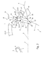
- Fig. 1 is a detail of a passenger car a convertible 1 shown, of which one above a waistline 2 open body 3 with a side door 4 and a rear side wall 5 is partially visible. Between a windshield 6 framing cowl 7 with an upper transverse frame leg 8 and a tail section 9 of the convertible 1, not shown in detail extends a removable roof 10, the in Fig. 1 in its one passenger compartment 11 spanning closed position ST on the convertible 1 is shown.
- a storage box 12 for the roof 10.
- the storage box 12 for example, a movable lid, which is not shown here, be assigned; Alternatively, the storage box 12 can do without such a lid.
- the roof 10 has at least two roof elements 13, of which one roof element 13 is a main roof element 14 of a main roof arrangement 15 and another roof element 13 is an additional roof element 16 of an additional roof arrangement 17. Furthermore, the roof 10 may have a rear roof element 18, possibly with a rear window (not shown).
- the main roof element 14 may abut in shooting position ST on the transverse frame leg 8 or it may - as in Fig. 1 shown - another roof element 13 may be provided as a roof top 19, which is in the closed position ST between the cowl 7 and the main roof element 14. All roof elements 13 and the rear roof element 18 are in series one behind the other. In an in Fig.
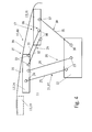
- FIG. 3 shown storage position AT, in which the roof 10 is at least partially received in the storage box 12, the roof elements 13 and the rear roof element 18 are superimposed, whereby the packing height of the roof 10 is given. It is in Fig. 3 further to see that in the storage position AT the front roof element 13, here the roof top 19, the storage box 12 at least partially closes.
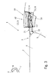
- the main roof assembly 15 includes the main roof member 14 and a main bearing means 20 for the main roof member 14 to move relative to the body 3 from the closed position ST to the storage position AT and vice versa.
- the main bearing device 20 has a main linkage 21 and a top bearing 22 to which the main linkage 21 is articulated with its one end in at least one first joint 23. With its other end, the main linkage 21 is movably connected to the main roof element 14 in at least one second joint 24.
- the top bearing 22 is integrally formed on the body 3 or attached to it as a separate component.
- the top bearing 22 with the at least one joint 23 is preferably below the belt line 2.
- the main linkage 21 as a two main link 25 and 26 comprising four-bar link 27 is formed with the joints 23 and 24.
- the further roof part 13, in this case the rooftop 19, is coupled to the main roof arrangement 15 in any desired type and design of suitable kinematics, which is not shown here, in order to selectively move it into the closed and stored positions ST and AT together with it can.
- the rear roof panel 18 is hinged either separately to the body 3 or to the main roof assembly 15 or to the auxiliary roof assembly 17 to move it between the closed position ST and the storage position AT can.
- the additional roof assembly 17 includes the additional roof element 16 and an additional storage device 28 for the additional roof element 16 in order to move it between the closed position ST and the storage position AT can.
- the closing movement of the roof 10 is oriented counter to the depositing movement, that is to say directed from the rear section 9 in the direction of the cowl 7.
- the additional bearing device 28 has a connection linkage 29 and a control linkage 30 for a corresponding movement and support of the additional dart element 16.
- With the linkage 29 is the additional roof assembly 17 with the main roof assembly 15 relative to this movably connected.
- the connecting link 29 has at least one connecting link 31 and / or 32, which is connected in a third joint 33 with the main roof assembly 15 and a fourth joint 34 with the additional roof assembly 17.
- the control rod 30 is used to control the movement of the formedachelements 16 between the two end positions (closed position ST and storage position AT) of the roof 10 and it has at least one control link 35, 36, in a fifth joint 37 with the additional roof assembly 17 and in a sixth joint 38 is connected to the top bearing 22.
- the connecting rod 29 has only one connecting link 31, 32 or at least one first and second connecting link 31, 32 and the control linkage 30 has only a first control link 35, 36 or at least one first and second control link 35, 36.
- the connecting linkage 29 in all embodiments, a number of connecting links 31, 32, which is different from the number of control links 35, 36 of the control linkage 30;
- the linkage 29 has a connecting link 31 or 32 and the control linkage 30 at least two control links 35 and 36, or the linkage 29 has at least two connecting links 31 and 32 and the control linkage 30 has only one of the control links 35 or 36.
- both the connecting rod 29 and the control rod 30 according to at least two connecting links 31 and 32 or two control links 35 and 36 equip.
- the associated first to sixth joints 23, 24, 33, 34, 37, 38 may be arranged as follows: The first joints 23 are located at the top bearing 22, the second joints 24 are located on the main roof element 14, the third joints 33 are located on the main roof element 14, the fourth joints 34 are located on the additional roof element 16 and / or on the control linkage 30, the fifth joints 37 are located on the additional roof element 16 and / or on the linkage 29, the sixth joints 38 are located on the top bearing 22nd
- the connecting linkage 29 has two connecting links 31 and 32, which are articulated in the third joints 33 on the main roof element 14 and in the fourth joints 34 on the additional roof element 16.
- the two connecting links 31, 32 are arranged as a four-bar link, with the third joints 33 lying one behind the other.
- the fourth joints 34 are also behind each other.
- the control linkage 30 has only one of the control links 35, the fifth joint 37 is located on the additional roof element 16 and the sixth joint 38 on the top bearing 22.
- the joints 34 and 37 lie one behind the other on the additional roof element 16.
- the roof 10 is still provided with an outer top cloth 39, which may comprise at least one layer or layer.
- the top cloth 39 extends from the front or front roof element 13, here the roof top 19, to above the rear roof element 18 (FIG. Fig. 1 to 3 ) away.
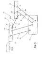
- the roof 10, in particular the additional bearing device 28, after Fig. 4 like the roof 10, in particular the additional bearing device 28, of the first embodiment according to the Fig. 1 to 3 educated.
- the roof elements 13 and the rear roof element 18 thereby form so-called surface arch, which support the top cloth 39 in the closed position ST in shape and therefore could also be designated shaping elements.
- the surface mirrors have a in Vehicle longitudinal direction measured length, which is significantly larger than a length of so-called known bow, which bow cause only a linear support of the top cloth 39.
- All roof elements 13 or surface arch and the rear roof element 18 (FIG. Fig. 1 to 3 ) are in series one behind the other, wherein it is preferably provided that the roof elements 13 and the rear roof element 18 abut each other in the closed position ST, so as to form a continuous shaping surface for the top cloth 39. Only a lateral, lying between the side wall 5 and above the waistline 2 column portion 40 '( Fig. 1 ), here the B-pillar section, the top cloth 39 ( Fig. 4 ) is not supported by roof elements 13.
- This column section 40 ' is defined here by, for example, three vertices D, E, F ( Fig. 1 ), wherein between D and F at least one so-called roof frame can be provided. E and F are connected by the belt line 2 and D and E are joined together by the lateral edges of the roof elements 13. Such a soft top or fabric top 40 with the top cloth 39 can be to those in the rest Fig. 5 to 9 shown roofs 10 may also be provided.
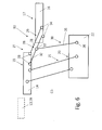
- the additional linkage 28 is formed as follows:
- the linkage 29 has only one of the connecting link 31, the third hinge 33 is located on the main roof element 14 and the fourth joint 34 is located on the additional roof element 16.
- the control linkage 30 here has two control links 35, 36, the fifth joints 37 lie on the additional roof element 16 and the sixth joints 38 are behind the other at the top bearing 22, so that the control rod 30 forms a four-bar linkage.
- At the additional roof element 16 are the fourth joint 34 and the two fifth joints 37 in a row.
- the additional bearing device 28 is equipped with a connecting link 29 with two connecting links 31 and 32 and the control linkage with only one control link 35, as in connection with the embodiment of the Fig. 1 to 3 is described.
- the only control link 35 is articulated with its fifth joint 37, however, on the linkage 29 and in particular on the connecting link 32, the from the two connecting links 31 and 32 may also be referred to as front or lower connecting link 32.
- the control link 35 is now articulated to the rear or upper connecting link 31 of the connecting linkage 29 with its fifth joint 37.
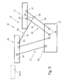
- a sixth embodiment of an additional bearing device 28, which in Fig. 8 can be seen, is characterized by a connecting link 29 with only one connecting link 31 which is articulated with its fourth joint 34 on the control linkage 30.
- the control linkage 30 comprises two control links 35 and 36.
- the fourth link 34 is located on the front control link 35, whereas in the seventh embodiment of an additional bearing device 28 accordingly Fig. 9 the fourth joint 34 is located on the rear control link 36. Otherwise, the roofs are 10 after the Fig. 8 and 9 like the roof 10 after Fig. 5 educated.
Landscapes
- Engineering & Computer Science (AREA)
- Mechanical Engineering (AREA)
- Fittings On The Vehicle Exterior For Carrying Loads, And Devices For Holding Or Mounting Articles (AREA)
- Body Structure For Vehicles (AREA)
Applications Claiming Priority (1)
| Application Number | Priority Date | Filing Date | Title |
|---|---|---|---|
| DE102007024171A DE102007024171A1 (de) | 2007-05-24 | 2007-05-24 | Ablegbares Dach für ein Cabriolet |
Publications (3)
| Publication Number | Publication Date |
|---|---|
| EP1995100A2 true EP1995100A2 (fr) | 2008-11-26 |
| EP1995100A3 EP1995100A3 (fr) | 2010-03-24 |
| EP1995100B1 EP1995100B1 (fr) | 2012-04-11 |
Family
ID=39457327
Family Applications (1)
| Application Number | Title | Priority Date | Filing Date |
|---|---|---|---|
| EP20080001998 Ceased EP1995100B1 (fr) | 2007-05-24 | 2008-02-02 | Capote pour un cabriolet |
Country Status (2)
| Country | Link |
|---|---|
| EP (1) | EP1995100B1 (fr) |
| DE (1) | DE102007024171A1 (fr) |
Citations (2)
| Publication number | Priority date | Publication date | Assignee | Title |
|---|---|---|---|---|
| US5785375A (en) | 1993-12-29 | 1998-07-28 | Asc Incorporated | Retractable hard-top for an automotive vehicle |
| DE10006296C1 (de) | 2000-02-14 | 2001-05-17 | Webasto Vehicle Sys Int Gmbh | Umwandelbares Fahrzeugdach |
Family Cites Families (6)
| Publication number | Priority date | Publication date | Assignee | Title |
|---|---|---|---|---|
| DE29913486U1 (de) * | 1999-08-03 | 2000-12-14 | Wilhelm Karmann GmbH, 49084 Osnabrück | Cabriolet-Fahrzeug |
| DE10019366C2 (de) * | 2000-04-18 | 2003-12-11 | Edscha Cabrio Dachsys Gmbh | Dachkonstruktion für ein Kraftfahrzeug mit abhebbarem Dach |
| DE10043703B4 (de) * | 2000-09-04 | 2009-07-30 | Webasto Ag | Absenkbares Fahrzeugdach |
| US6695386B1 (en) * | 2002-09-18 | 2004-02-24 | Asc Incorporated | Vehicle retractable hardtop roof |
| FI20040204A0 (fi) * | 2004-02-10 | 2004-02-10 | Valmet Automotive Oy | Avoauton avattava katto |
| DE102004029148B3 (de) * | 2004-06-17 | 2006-03-02 | Cts Fahrzeug-Dachsysteme Gmbh | Hardtop-Fahrzeugdach mit mindestens zwei Dachteilen |
-
2007
- 2007-05-24 DE DE102007024171A patent/DE102007024171A1/de not_active Withdrawn
-
2008
- 2008-02-02 EP EP20080001998 patent/EP1995100B1/fr not_active Ceased
Patent Citations (2)
| Publication number | Priority date | Publication date | Assignee | Title |
|---|---|---|---|---|
| US5785375A (en) | 1993-12-29 | 1998-07-28 | Asc Incorporated | Retractable hard-top for an automotive vehicle |
| DE10006296C1 (de) | 2000-02-14 | 2001-05-17 | Webasto Vehicle Sys Int Gmbh | Umwandelbares Fahrzeugdach |
Also Published As
| Publication number | Publication date |
|---|---|
| EP1995100B1 (fr) | 2012-04-11 |
| DE102007024171A1 (de) | 2008-11-27 |
| EP1995100A3 (fr) | 2010-03-24 |
Similar Documents
| Publication | Publication Date | Title |
|---|---|---|
| EP1108581B1 (fr) | Toit pliant pour véhicule, notamment véhicules de tourisme | |
| DE10050286A1 (de) | Mehrteilige Abdeckung für Fahrzeuge | |
| DE4316485A1 (de) | Klappverdeck für Kraftfahrzeuge | |
| DE19939954B4 (de) | Faltschiebedachanordnung | |
| DE10348726B4 (de) | Personenkraftwagen mit Aufbauöffnungen | |
| EP1331122B1 (fr) | Toit rigide rétractable pour véhicule automobile | |
| DE10164845B4 (de) | Klappverdeck für ein Cabriolet-Fahrzeug | |
| DE10326981B4 (de) | Fahrzeug, das von einem Pick-up in ein Cabrio umwandelbar ist | |
| EP1971501A1 (fr) | Toit décapotable pour automobile | |
| EP1897718B1 (fr) | Capote pliable | |
| DE102007032674A1 (de) | Bewegliches Dach für einen Personenkraftwagen | |
| DE102007004180B4 (de) | Verstellbares Fahrzeugdach | |
| EP2004432B1 (fr) | Capote de toit ouvrant pour un vehicule automobile ouvert | |
| EP1744920B1 (fr) | Structure toit d'un toit rigide a ouvrir d'un vehicule automobile | |
| DE102004029148B3 (de) | Hardtop-Fahrzeugdach mit mindestens zwei Dachteilen | |
| EP1995100B1 (fr) | Capote pour un cabriolet | |
| EP2036753B1 (fr) | Agencement de capote pour un cabriolet | |
| DE102007054469B4 (de) | Fahrzeugverdeck | |
| DE19714106A1 (de) | Umwandelbares Fahrzeugdach | |
| DE102015106311B4 (de) | Cabrioletverdeck mit Koppellenkereinheit | |
| DE9307481U1 (de) | Klappverdeck für Kraftfahrzeuge | |
| DE10161394B4 (de) | Dachkinematik für ein Hardtop-Fahrzeugdach mit mindestens zwei starren Dachteilen | |
| DE10213549B4 (de) | Cabriolet-Fahrzeug mit mehrteiligem Verdeck | |
| DE102013012830B3 (de) | Faltbares Verdeck für ein Cabriolet-Fahrzeug mit einem höhenverstellbaren Dachspriegel sowie Cabriolet-Fahrzeug mit einem solchen faltbaren Verdeck | |
| DE102014217097B4 (de) | Vorrichtung zur Verstellung eines Fahrzeugdachs |
Legal Events
| Date | Code | Title | Description |
|---|---|---|---|
| PUAI | Public reference made under article 153(3) epc to a published international application that has entered the european phase |
Free format text: ORIGINAL CODE: 0009012 |
|
| AK | Designated contracting states |
Kind code of ref document: A2 Designated state(s): AT BE BG CH CY CZ DE DK EE ES FI FR GB GR HR HU IE IS IT LI LT LU LV MC MT NL NO PL PT RO SE SI SK TR |
|
| AX | Request for extension of the european patent |
Extension state: AL BA MK RS |
|
| PUAL | Search report despatched |
Free format text: ORIGINAL CODE: 0009013 |
|
| AK | Designated contracting states |
Kind code of ref document: A3 Designated state(s): AT BE BG CH CY CZ DE DK EE ES FI FR GB GR HR HU IE IS IT LI LT LU LV MC MT NL NO PL PT RO SE SI SK TR |
|
| AX | Request for extension of the european patent |
Extension state: AL BA MK RS |
|
| RAP1 | Party data changed (applicant data changed or rights of an application transferred) |
Owner name: DR. ING. H.C. F. PORSCHE AG |
|
| 17P | Request for examination filed |
Effective date: 20100924 |
|
| 17Q | First examination report despatched |
Effective date: 20101026 |
|
| AKX | Designation fees paid |
Designated state(s): DE FR GB IT |
|
| GRAP | Despatch of communication of intention to grant a patent |
Free format text: ORIGINAL CODE: EPIDOSNIGR1 |
|
| GRAS | Grant fee paid |
Free format text: ORIGINAL CODE: EPIDOSNIGR3 |
|
| GRAA | (expected) grant |
Free format text: ORIGINAL CODE: 0009210 |
|
| AK | Designated contracting states |
Kind code of ref document: B1 Designated state(s): DE FR GB IT |
|
| REG | Reference to a national code |
Ref country code: GB Ref legal event code: FG4D Free format text: NOT ENGLISH |
|
| REG | Reference to a national code |
Ref country code: DE Ref legal event code: R096 Ref document number: 502008006892 Country of ref document: DE Effective date: 20120606 |
|
| PLBE | No opposition filed within time limit |
Free format text: ORIGINAL CODE: 0009261 |
|
| STAA | Information on the status of an ep patent application or granted ep patent |
Free format text: STATUS: NO OPPOSITION FILED WITHIN TIME LIMIT |
|
| 26N | No opposition filed |
Effective date: 20130114 |
|
| REG | Reference to a national code |
Ref country code: DE Ref legal event code: R097 Ref document number: 502008006892 Country of ref document: DE Effective date: 20130114 |
|
| REG | Reference to a national code |
Ref country code: FR Ref legal event code: PLFP Year of fee payment: 9 |
|
| REG | Reference to a national code |
Ref country code: FR Ref legal event code: PLFP Year of fee payment: 10 |
|
| REG | Reference to a national code |
Ref country code: FR Ref legal event code: PLFP Year of fee payment: 11 |
|
| PGFP | Annual fee paid to national office [announced via postgrant information from national office to epo] |
Ref country code: IT Payment date: 20190225 Year of fee payment: 12 |
|
| PGFP | Annual fee paid to national office [announced via postgrant information from national office to epo] |
Ref country code: FR Payment date: 20190220 Year of fee payment: 12 |
|
| PGFP | Annual fee paid to national office [announced via postgrant information from national office to epo] |
Ref country code: GB Payment date: 20200219 Year of fee payment: 13 Ref country code: DE Payment date: 20200227 Year of fee payment: 13 |
|
| PG25 | Lapsed in a contracting state [announced via postgrant information from national office to epo] |
Ref country code: FR Free format text: LAPSE BECAUSE OF NON-PAYMENT OF DUE FEES Effective date: 20200229 |
|
| REG | Reference to a national code |
Ref country code: DE Ref legal event code: R119 Ref document number: 502008006892 Country of ref document: DE |
|
| GBPC | Gb: european patent ceased through non-payment of renewal fee |
Effective date: 20210202 |
|
| PG25 | Lapsed in a contracting state [announced via postgrant information from national office to epo] |
Ref country code: IT Free format text: LAPSE BECAUSE OF NON-PAYMENT OF DUE FEES Effective date: 20200202 |
|
| PG25 | Lapsed in a contracting state [announced via postgrant information from national office to epo] |
Ref country code: DE Free format text: LAPSE BECAUSE OF NON-PAYMENT OF DUE FEES Effective date: 20210901 Ref country code: GB Free format text: LAPSE BECAUSE OF NON-PAYMENT OF DUE FEES Effective date: 20210202 |