EP1995189A1 - Lagerungsvorrichtung - Google Patents
Lagerungsvorrichtung Download PDFInfo
- Publication number
- EP1995189A1 EP1995189A1 EP06728964A EP06728964A EP1995189A1 EP 1995189 A1 EP1995189 A1 EP 1995189A1 EP 06728964 A EP06728964 A EP 06728964A EP 06728964 A EP06728964 A EP 06728964A EP 1995189 A1 EP1995189 A1 EP 1995189A1
- Authority
- EP
- European Patent Office
- Prior art keywords
- mount
- stored
- moving mechanism
- articles
- tables
- Prior art date
- Legal status (The legal status is an assumption and is not a legal conclusion. Google has not performed a legal analysis and makes no representation as to the accuracy of the status listed.)
- Withdrawn
Links
Images







Classifications
-
- B—PERFORMING OPERATIONS; TRANSPORTING
- B65—CONVEYING; PACKING; STORING; HANDLING THIN OR FILAMENTARY MATERIAL
- B65G—TRANSPORT OR STORAGE DEVICES, e.g. CONVEYORS FOR LOADING OR TIPPING, SHOP CONVEYOR SYSTEMS OR PNEUMATIC TUBE CONVEYORS
- B65G1/00—Storing articles, individually or in orderly arrangement, in warehouses or magazines
- B65G1/02—Storage devices
- B65G1/04—Storage devices mechanical
- B65G1/0478—Storage devices mechanical for matrix-arrangements
-
- B—PERFORMING OPERATIONS; TRANSPORTING
- B29—WORKING OF PLASTICS; WORKING OF SUBSTANCES IN A PLASTIC STATE IN GENERAL
- B29D—PRODUCING PARTICULAR ARTICLES FROM PLASTICS OR FROM SUBSTANCES IN A PLASTIC STATE
- B29D30/00—Producing pneumatic or solid tyres or parts thereof
- B29D30/005—General arrangement or lay-out of plants for the processing of tyres or parts thereof
-
- B—PERFORMING OPERATIONS; TRANSPORTING
- B29—WORKING OF PLASTICS; WORKING OF SUBSTANCES IN A PLASTIC STATE IN GENERAL
- B29D—PRODUCING PARTICULAR ARTICLES FROM PLASTICS OR FROM SUBSTANCES IN A PLASTIC STATE
- B29D30/00—Producing pneumatic or solid tyres or parts thereof
- B29D30/06—Pneumatic tyres or parts thereof (e.g. produced by casting, moulding, compression moulding, injection moulding, centrifugal casting)
- B29D30/0601—Vulcanising tyres; Vulcanising presses for tyres
- B29D30/065—Tyre-vulcanising presses with two or more moulds, e.g. stacked upon each other
- B29D2030/0651—Tyre-vulcanising presses with two or more moulds, e.g. stacked upon each other the moulds being arranged side by side, or in a circle
Definitions
- the present invention relates to a storage device, and more particularly to a storage device having improved efficiency in accommodation and storage of a plurality of articles of different outline sizes.
- such a storage device has a drawback in that, since the mount tables are arranged to the dimension of a product having the maximum outline size, placement of products having the minimum outline size on the mount tables involves occurrence of a large space between adjacent products having the minimum outline size, resulting in occurrence of useless storage space.
- Patent Document 1 Japanese Patent Application Laid-Open ( kokai ) No. 2000-95309
- An object of the present invention is to solve the above-mentioned problems in the conventional storage device and to provide a storage device which can flexibly and readily cope with storage of a plurality of articles-to-be-stored of various sizes and which, even when an article feature raises a large dimensional difference between an article-to-be-stored having a maximum outline size and an article-to-be-stored having a minimum outline size, can prevent occurrence of useless storage space to the greatest possible extent, thereby effectively utilizing storage space.
- the storage device has a plurality of mount tables capable of storing a plurality of articles-to-be-stored of different sizes placed thereon in a one-to-one correspondence, and at least one transfer device moving in an upper horizontal plane located above the plurality of mount tables while holding the article-to-be-stored.
- the transfer device comprises a holding mechanism for holding the article-to-be-stored; a vertically moving mechanism for vertically moving the holding mechanism; and a horizontally moving mechanism for moving the vertically moving mechanism in the upper horizontal plane.
- the plurality of the mount tables store the articles-to-be-stored placed thereon such that the adjacent articles-to-be-stored are spaced apart from each other by a predetermined interval in a lower horizontal plane, and have a mount-table-moving mechanism movable in at least one direction in a horizontal plane.
- the plurality of mount tables capable of storing a plurality of articles-to-be-stored of different sizes placed thereon in a one-to-one correspondence store the articles-to-be-stored placed thereon such that the adjacent articles-to-be-stored are spaced apart from each other by a predetermined interval in the lower horizontal plane, and have the mount-table-moving mechanism movable in at least one direction in a horizontal plane.
- the mount-table-moving mechanism is operated for moving the mount tables on which the articles-to-be-stored of a relevant size are respectively placed, to positions where useless storage space would otherwise arise.
- the storage device can flexibly and readily cope with storage of the plurality of articles-to-be-stored of various sizes. Even when an article feature raises a large dimensional difference between an article-to-be-stored having a maximum outline size and an article-to-be-stored having a minimum outline size, the storage device can prevent occurrence of useless storage space to the greatest possible extent, thereby effectively utilizing storage space.
- the plurality of mount tables have the mount-table-moving mechanism for each of the mount tables.
- the plurality of mount tables have the mount-table-moving mechanism for each group of mount tables, and the mount-table-moving mechanism can move the group of mount tables all together.
- the group of mount tables to be moved all together by the mount-table-moving mechanism are arranged in series in an X-direction or in a Y-direction.
- the group of mount tables to be moved all together by the mount-table-moving mechanism are moved in the Y-direction or in the X-direction.
- the group of mount tables to be arranged in series in the X-direction or in the Y-direction store a plurality of articles-to-be-stored of the same size placed thereon in a one-to-one correspondence.
- a plurality of articles-to-be-stored of the same size are placed and stored on the respective mount tables on a row or column basis; thus, management of the plurality of articles-to-be-stored can be further facilitated.
- the plurality of mount tables capable of storing a plurality of articles-to-be-stored of different sizes placed thereon in a one-to-one correspondence store the articles-to-be-stored placed thereon such that the adjacent articles-to-be-stored are spaced apart from each other by a predetermined interval in the lower horizontal plane, and have the mount-table-moving mechanism movable in at least one direction in a horizontal plane.
- the mount-table-moving mechanism is operated for moving the mount tables on which the articles-to-be-stored of a relevant size are respectively placed, to positions where useless storage space would otherwise arise.
- the storage device can flexibly and readily cope with storage of the articles-to-be-stored of various sizes. Even when an article feature raises a large dimensional difference between an article-to-be-stored having a maximum outline size and an article-to-be-stored having a minimum outline size, the storage device can prevent occurrence of useless storage space to the greatest possible extent, thereby effectively utilizing storage space.
- the mount-table-moving mechanism can move the group of mount tables all together, when the size of the articles-to-be-stored of a certain group is changed, the mount tables on which these articles-to-be-stored are to be respectively placed can be moved to relevant positions all together, thereby improving work efficiency.
- a plurality of articles-to-be-stored of different sizes can be managed on a row or column basis, thereby facilitating management of the plurality of articles-to-be-stored of different sizes.
- the mount tables can be moved efficiently through travel along a shortest moving distance.
- the group of mount tables to be arranged in series in the X-direction or in the Y-direction store a plurality of articles-to-be-stored of the same size placed thereon in a one-to-one correspondence
- the plurality of articles-to-be-stored of the same size are placed and stored on the respective mount tables on a row or column basis; thus, management of the plurality of articles-to-be-stored can be further facilitated.
- 1 storage device; 100: mount-table-moving mechanism; 101: first frame; 102: second frame; 103: slide rail; 104: slide rail; 105: rail-mounting member; 106: first fixing member (screw member); 200: mount table group; 201: second fixing member (screw member); 202: fixing member; 203: auxiliary fixing member (screw member); 204: mount member; 205: pin; 206: article sensor; 300: transfer device; 300a, 300b: first and second transfer devices (a pair of three-dimensionally-moving mechanisms); 301: support; 302: stationary guide rail; 303a, 303b: a pair of traveling guide rails; 304a, 304b: a pair of horizontally-vertically moving mechanisms; 305a, 305b: a pair of article-to-be-stored-holding mechanisms; 400: storing conveyance device; 401: carrying-in position; 500: delivering conveyance device; 501: carrying-out position; 600: tire mold group; D,
- the storage device has a plurality of mount tables capable of storing a plurality of articles-to-be-stored of different sizes placed thereon in a one-to-one correspondence, and at least one transfer device moving in an upper horizontal plane located above the plurality of mount tables while holding the article-to-be-stored.
- the transfer device includes a holding mechanism for holding the article-to-be-stored; a vertically moving mechanism for vertically moving the holding mechanism; and a horizontally moving mechanism for moving the vertically moving mechanism in the upper horizontal plane.
- the plurality of the mount tables store the articles-to-be-stored placed thereon such that the adjacent articles-to-be-stored are spaced apart from each other by a predetermined interval in a lower horizontal plane, and have a mount-table-moving mechanism movable in at least one direction in a horizontal plane.
- the plurality of the mount tables have the mount-table-moving mechanism for each of the mount tables or for each group of mount tables.
- the group of mount tables can be moved all together.
- the group of mount tables to be moved all together by the mount-table-moving mechanism are arranged in series in an X-direction or in a Y-direction; are moved in the Y-direction or in the X-direction; and store a plurality of articles-to-be-stored of the same size placed thereon in a one-to-one correspondence.
- FIG. 1 is a plan view of a storage device of the present embodiment
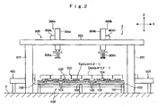
- FIG. 2 is a schematic front view of the storage device
- FIG. 3 is a schematic left side view of the storage device with a storing conveyance device removed
- FIG. 4 is an enlarged partial view of FIG. 1
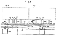
- FIG. 5 is a front view of a portion corresponding to FIG. 4
- FIG. 6 is a right side view of a portion corresponding to FIG. 4 .
- the storage device of the present embodiment is used to accommodate and store a plurality of articles of different outline magnitudes (sizes); for example, tire molds.
- a tire mold is taken as an example of an article to be stored (article-to-be-stored).
- the article-to-be-stored is not limited thereto.
- the storage device of the present embodiment can be used to store not only articles having similar circular outlines but also articles having similar outlines and different outline sizes.
- suffixes a and b in symbols Tab and Dab indicate a column number and a row number assigned along an X-direction and in a Y-direction, respectively, for a regular array in the X- and Y-directions of the mount table group 200.
- the column-row number is counted starting from the mount table T11 located at the upper left corner.
- a mount table indicated by symbol T23 i.e., the mount table T23, is located in the second column in the X-direction and the third row in the Y-direction.
- a tire mold indicated by symbol D23 i.e., the tire mold D23
- the mount table T23 located in the second column in the X-direction and the third row in the Y-direction.
- suffix a assumes a number of 1 to 8
- suffix b assumes a number of 1 to 5
- a tire mold to which the column-row number a, b is not assigned is represented merely as the "tire mold D.”
- the column-row number a, b can increment or decrement as appropriate.
- the mount-table-moving mechanism 100 is configured as follows.
- a plurality of (in the present embodiment, three) slide rails 103 extending in the Y-direction are mounted on a first frame 101, which is framed on the floor F by use of structural members (see FIGS. 5 and 6 ) each having the form of a duct having a squarish cross section.
- a plurality of (in the present embodiment, five) second frames 102 extending in the X-direction are laid on the slide rails 103 in such a manner as to be movable and fixable in the Y-direction.
- a pair of slide rails 104 extending in the X-direction are mounted on each of the second frames 102 via rail-mounting members 105.
- a plurality of (in the present embodiment, eight) mount tables Tab (a 1 to 8) ride on each pair of the slide rails 104 in a straddling manner and in such a manner as to be movable and fixable in the X-direction.
- One tire mold Dab is placed on one mount table Tab.
- each of the second frames 102 can be fixed or rendered movable in the Y-direction on the slide rails 103 by establishing or canceling engagement between engaging members (members each having a projection) provided in a protruding condition on the lower side of the second frame 102 and traveling-guide engagement grooves formed in the slide rails 103, through operation of first fixing members 106 (see FIG. 5 ) provided on the second frame 102.
- Each of the first fixing members 106 is a screw member and is screwed through a threaded hole formed vertically in the second frame 102, and an externally threaded end portion of the first fixing member 106 is threadingly engaged with an internally threaded portion of the corresponding engaging member provided on the second frame 102.
- the engaging member of the second frame 102 advances or retreats, thereby loosening or tightening the engaged condition between the engaging member and the traveling-guide engagement groove of the slide rail 103.
- the engagement structure between the engaging member provided on the second frame 102 and the traveling-guide engagement groove provided on the slide rail 103 is not limited to the above-described structure, but may be modified in various forms.
- the mount table Tab can be fixed or rendered movable in the X-direction on the paired slide rails 104 by operating four screw members 201 (second fixing members; see FIG. 4 ) which are screwed through four respective threaded holes formed at four corners of a table wall of the mount table Tab, so as to loosen or tighten threading engagements associated with the screw members 201.
- screw members 201 second fixing members; see FIG. 4
- two fixing members 202 each having a rectangular parallelepiped shape are disposed at one side of the mount table Tab with respect to the Y-direction such that the fixing members 202 are in contact with opposite side surfaces of the mount table Tab with respect to the X-direction.
- the fixing members 202 are fixedly mounted by means of auxiliary fixing members 203.
- the auxiliary fixing members 203 are screw members.
- the two screw members 203 are screwed through two respective threaded holes formed through each of the fixing members 202.
- the two screw members 203 are operated so as to tighten threading engagements associated with the screw members 203, whereby the mount table Tab can be fixed more firmly on the paired slide rails 104.
- An engagement structure between an engaging member provided on the mount table Tab and an engaging member provided on the slide rail 104 which is employed for fixing the mount table Tab on the paired slide rails 104 by means of tightening threading engagements associated with the screw members 201 and threading engagements associated with the screw members 203 may be basically similar to that between the engaging member provided on the second frame 102 and the traveling-guide engagement groove provided on the slide rail 103 which is employed for fixing the second frame 102 on the slide rails 103 by means of tightening threading engagements associated with the screw members 106.
- Each of the mount tables Tab can move in the X-direction on the paired slide rails 104 in the row B in the Y-direction.
- a mechanism which enables a plurality of (in the present embodiment, eight) the mount tables Tab in the row b in the Y-direction to move in the X-direction on an individual basis and which enables the plurality of mount tables Tab to move all together in the Y-direction is herein called the "mount-table-moving mechanism.”
- the mount-table-moving mechanism 100 is roughly composed of the first frame 101, three slide rails 103, one second frame 102, and a pair of the slide rails 104. A total of five mount-table-moving mechanisms 100 are provided while the first frame 101 and the three slide rails 103 are used in common. Of course, the number of the mount-table-moving mechanisms 100 may be increased or decreased as appropriate.
- storage space is utilized with high effectiveness.
- a plurality of the mount tables Tab (a 1, 2%) in the row b in the Y-direction ride on each pair of the slide rails 104.
- FIGS. 1 to 3 four supports 301 stand on the floor F and support a pair of horizontal, stationary guide rails 302, which extend in the X-direction in parallel with each other.
- a pair of traveling guide rails 303a, 303b lie between and on the paired horizontal, stationary guide rails 302 in a straddling manner and in such a manner as to be movable in the X-direction while extending along the Y-direction.
- Paired horizontally-vertically moving mechanisms 304a, 304b are movably attached to the paired traveling guide rails 303a, 303b, respectively.
- Each of the paired horizontally-vertically moving mechanisms 304a, 304b has a built-in traveler capable of traveling along the relevant traveling guide rail 303a or 303b, and a built-in elevating mechanism capable of moving vertically.
- the four supports 301, the paired stationary guide rails 302, the paired traveling guide rails 303a, 303b, and the paired travelers incorporated respectively in the paired horizontally-vertically moving mechanisms 304a, 304b constitute a pair of horizontally moving mechanisms, which share the four supports 301 and the paired stationary guide rails 302.
- the paired horizontally moving mechanisms, and the paired elevating mechanisms incorporated respectively in the paired horizontally-vertically moving mechanisms 304a, 304b constitute a pair of three-dimensionally moving mechanisms, which share the four supports 301 and the paired stationary guide rails 302; in other words, a pair of transfer devices 300a, 300b (hereinafter, referred to as the first and second transfer devices 300a, 300b).
- the transfer device 300 is a general term for the first and second transfer devices 300a, 300b.
- the above-mentioned horizontally moving mechanism and three-dimensionally moving mechanism are well known and are disclosed in, for example, Japanese Patent Application Laid-Open (kokai) No. 2003-72944 filed by the applicant of the present invention.
- Paired article-to-be-stored-holding mechanisms 305a, 305b are attached to lower portions of the paired horizontally-vertically moving mechanisms 304a, 304b, respectively.
- each of the paired article-to-be-stored-holding mechanisms 305a, 305b can hold the tire mold Dab placed on the mount table Tab or the tire mold D placed at a carrying-in position 401 of a storing conveyance device 400, and also can release the tire mold Dab which it holds onto the mount table Tab or the like.
- the article-to-be-stored-holding mechanism 305a is lowered by the horizontally-vertically moving mechanism 304a and then releases the tire mold Dab which it holds, onto the predetermined mount table Tcd or onto the carrying-out position 501 of the delivering conveyance device 500, thereby placing the tire mold Dab thereon.
- the mount table Tab has three mount members 204 standing on its upper surface at circumferentially equal intervals and adapted to actually support the tire mold Dab.
- One of the three mount members 204 has a pin 205 projecting from its top face and adapted to position the tire mold Dab on the three mount members 204.
- the pin 205 is fitted into a pin hole which is formed on the rear side of the tire mold Dab at a predetermined position, thereby circumferentially positioning the tire mold Dab which is held by the article-to-be-stored-holding mechanism 305a or 305b.
- the mount table Tab also has an article sensor 206 provided on its upper surface and adapted to detect whether or not the tire mold Dab is present.
- the mount table Ta-1b is moved on the paired slide rails 104 in the X-direction by a predetermined distance corresponding to the size of the tire mold D'a-1b to be newly placed. Then, the four auxiliary fixing members (screw members) 203 and the four second fixing members (screw members) 201 are tightened again, thereby fixing the mount table Ta-1b on the paired slide rails 104 (step 2 shown in FIG. 8(b) ).
- step 2 may be modified as follows.
- the mount table Ta-1b is moved to a rough position (where the tire mold D'a-1b to be newly placed on the mount table Ta-1b and the tire mold Dab placed on the mount table Tab do not interfere with each other) on the paired slide rails 104. Subsequently, the tire mold D'a-1b is actually placed on the mount table Ta-1b. Then, the mount table Ta-1b is positionally adjusted to a precise position and is then fixed.
- the new tire mold D'a-1b is moved to a position located immediately above the mount table Ta-1b and is then lowered and placed on the mount table Ta-1b. Then, relative arrangement is checked for interference between the tire mold D'a-1b and the adjacent tire mold Dab and the like. Subsequently, in order that the position of the article-to-be-stored-holding mechanism 305a or 305b of the transfer device 300 and the position of the mount table Ta-1b agree with each other, positional check is performed, and positional information about the mount table Ta-1b stored in the transfer device 300 is revised accordingly (step 3 shown in FIG. 8(c) ).
- the first fixing members (screw members) 106 are operated so as to loosen and tighten threading engagements associated with the first fixing members 106.
- the associated second frame 102 is moved in the Y-direction on the slide rails 103 by a predetermined distance and is then fixed, thereby setting the mount table Ta-1b at a predetermined position in the Y-direction.
- the previously described moving procedure may be followed.
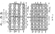
- the tire molds Dab of the small size placed on the mount tables Tab are arranged in three columns in the X-direction and in four rows in the Y-directional; the tire molds D'ab of the medium size placed on the mount tables Tab are arranged in three columns in the X-direction and in four rows in the Y-direction; and the tire molds D"ab of the large size placed on the mount tables Tab are arranged in one column in the X-direction and in four rows in the Y-direction.
- all of the tire molds are stored at optimum intervals, thereby effectively utilizing storage space.
- the arrangement of the tire molds D in the present embodiment may be such that the X-directional arrangement of the tire molds D in the row 2 in the Y-direction is symmetrical with that of the tire molds D in the row 1 in the Y-direction. This enables far more effective utilization of storage space along the Y-direction.
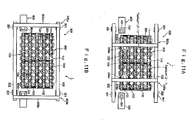
- the traveling guide rail 303a and the horizontally-vertically moving mechanism 304a which constitute the first transfer device 300a, move toward the position of a mount table T41 which is located within the storage area and on which the tire mold D41 is to be placed.
- the built-in elevating mechanism of the horizontally-vertically moving mechanism 304a lowers from above the mount table T41.
- the article-to-be-stored-holding mechanism 305a attached to the lower portion of the elevating mechanism releases the tire mold D41 onto the mount table T41, thereby placing the tire mold D41 on the mount table T41.
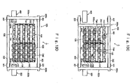
- the elevating mechanism rises again (see FIG. 11C ).
- the traveling guide rail 303a and the horizontally-vertically moving mechanism 304a which constitute the first transfer device 300a, move again toward the carrying-in position 401 of the storing conveyance device 400 and stand by until the next tire mold D is conveyed to the carrying-in position 401 (see FIG. 11D ).
- the traveling guide rail 303b and the horizontally-vertically moving mechanism 304b which constitute the second transfer device 300b, move toward the carrying-out position 501 of the delivering conveyance device 500.
- the built-in elevating mechanism of the horizontally-vertically moving mechanism 304b lowers from a position above the carrying-out position 501.
- the article-to-be-stored-holding mechanism 305b attached to the lower portion of the elevating mechanism releases the tire mold D65 onto the carrying-out position 501, thereby placing the tire mold D65 at the carrying-out position 501.
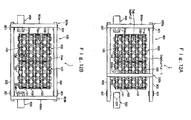
- the elevating mechanism rises again (see FIG. 12B ).
- the traveling guide rail 303b and the horizontally-vertically moving mechanism 304b which constitute the second transfer device 300b, maintain the article-to-be-stored-holding mechanism 305b in an elevated condition and stand by at the position without moving horizontally until the next instruction is received (see FIG. 12B ).
- the second transfer device 300b stands by at a position located above the carrying-out position 501 of the delivering conveyance device 500, and the first transfer device 300a moves to a position located above a mount table T15, which is located nearest to the carrying-in position 401 of the storing conveyance device 400 among a plurality of the mount tables Tab on which a plurality of the tire molds Dab are respectively placed.
- the built-in elevating mechanism of the horizontally-vertically moving mechanism 304a lowers.
- the article-to-be-stored-holding mechanism 305a attached to a lower portion of the elevating mechanism holds a tire mold D15 (not shown) placed on the mount table T15, and the elevating mechanism rises again (see FIG. 13A ).
- the first transfer device 300a moves to a position located above a mount table T84, which is located nearest to the carrying-out position 501 of the delivering conveyance device 500 among a plurality of vacant mount tables Tab. Then, the built-in elevating mechanism of the horizontally-vertically moving mechanism 304a lowers. The article-to-be-stored-holding mechanism 305a attached to the lower portion of the elevating mechanism releases the tire mold D15 onto the mount table T84, thereby placing the tire mold D15 on the mount table T84. Then, the elevating mechanism rises again (see FIG. 13B ).
- the first transfer device 300a moves to a position located above a mount table T14, which is located second nearest to the carrying-in position 401 of the storing conveyance device 400, and repeats the above-described operation (see FIG. 13C ).
- a new column-row number is assigned to the tire mold D15 which was previously placed on the mount table T84, so that the tire mold D15 is indicated as the tire mold D84.
- the first transfer device 300a moves to a position located above the carrying-in position 401 of the storing conveyance device 400 and stands by at the position (see FIG. 13D ).
- the storage device 1 of the present embodiment is configured as described above and can therefore yield the following effects.
- the mount-table-moving mechanism 100 is operated for moving the mount tables Tab on which the tire molds Dab of a relevant size are respectively placed, to positions where useless storage space would otherwise arise.
- the storage device can prevent occurrence of useless storage space to the greatest possible extent, thereby effectively utilizing storage space.
- the present invention is not limited to the above-described embodiment. Numerous modifications and variations of the present invention are possible without departing from the gist of the invention.
- a plurality of the mount tables may be arranged in series in the Y-direction. In this case, the structure of the mount-table-moving mechanism 100 is changed such that the slide rails 103 are laid along the X-direction and such that pairs of the slide rails 104 are laid along the Y-direction.
Landscapes
- Engineering & Computer Science (AREA)
- Mechanical Engineering (AREA)
- Physics & Mathematics (AREA)
- Mathematical Physics (AREA)
- Warehouses Or Storage Devices (AREA)
- Carriers, Traveling Bodies, And Overhead Traveling Cranes (AREA)
Applications Claiming Priority (1)
| Application Number | Priority Date | Filing Date | Title |
|---|---|---|---|
| PCT/JP2006/304849 WO2007105283A1 (ja) | 2006-03-13 | 2006-03-13 | 保管装置 |
Publications (2)
| Publication Number | Publication Date |
|---|---|
| EP1995189A1 true EP1995189A1 (de) | 2008-11-26 |
| EP1995189A4 EP1995189A4 (de) | 2009-04-01 |
Family
ID=38509133
Family Applications (1)
| Application Number | Title | Priority Date | Filing Date |
|---|---|---|---|
| EP06728964A Withdrawn EP1995189A4 (de) | 2006-03-13 | 2006-03-13 | Lagerungsvorrichtung |
Country Status (4)
| Country | Link |
|---|---|
| US (1) | US20090202331A1 (de) |
| EP (1) | EP1995189A4 (de) |
| JP (1) | JP5021618B2 (de) |
| WO (1) | WO2007105283A1 (de) |
Families Citing this family (1)
| Publication number | Priority date | Publication date | Assignee | Title |
|---|---|---|---|---|
| CN106573728B (zh) * | 2014-09-10 | 2019-09-24 | 村田机械株式会社 | 临时保管系统、使用了它的输送系统和临时保管方法 |
Family Cites Families (12)
| Publication number | Priority date | Publication date | Assignee | Title |
|---|---|---|---|---|
| US3951282A (en) * | 1973-10-24 | 1976-04-20 | Alex Jacques Keller | Method for feeding fibers |
| DE3222148A1 (de) * | 1982-06-11 | 1983-12-15 | Albert 5600 Wuppertal Fischbach | Vollautomatisches regallager |
| DE3601297A1 (de) * | 1986-01-17 | 1987-07-23 | Waertsilae Strecker Gmbh | Vorrichtung zur beschickung einer maschine mit warenbahnen von einer mehrzahl vorratsrollen |
| ES2107700T3 (es) * | 1993-03-24 | 1997-12-01 | Hauni Maschinenbau Ag | Brazo de robot de un robot de porticos de superficie. |
| US5820885A (en) * | 1993-09-14 | 1998-10-13 | Mitsubishi, Jukogyo Kabushiki Kaisha | Tire vulcanizing system |
| WO1995032146A1 (de) * | 1994-05-20 | 1995-11-30 | Tax Ingenieurgesellschaft Mbh | Lastenverladekran |
| FI972687A7 (fi) * | 1997-06-19 | 1998-12-20 | Teco Engineering Oy | Menetelmä ja laitteisto konttien lastaamiseksi alukseen ja purkamiseksi aluksesta |
| JP2000095309A (ja) | 1998-09-25 | 2000-04-04 | Okuma Corp | ロール状物品保管装置 |
| AU1332600A (en) * | 1998-10-30 | 2000-05-22 | C&D Robotics, Inc. | Universal tire stacking and palletizing end effector assembly and system and method of using same |
| JP3484104B2 (ja) * | 1998-12-25 | 2004-01-06 | 平田機工株式会社 | 自動倉庫及び自動倉庫の管理方法 |
| US6579053B1 (en) * | 1999-03-15 | 2003-06-17 | Abb Flexible Automation, Inc. | Robotic containerization and palletizing system |
| JP2003072921A (ja) * | 2001-09-05 | 2003-03-12 | Yodo Casting:Kk | 物品の保管位置等をアドレス管理する方法 |
-
2006
- 2006-03-13 EP EP06728964A patent/EP1995189A4/de not_active Withdrawn
- 2006-03-13 WO PCT/JP2006/304849 patent/WO2007105283A1/ja not_active Ceased
- 2006-03-13 JP JP2008504937A patent/JP5021618B2/ja not_active Expired - Fee Related
- 2006-03-13 US US12/224,712 patent/US20090202331A1/en not_active Abandoned
Also Published As
| Publication number | Publication date |
|---|---|
| US20090202331A1 (en) | 2009-08-13 |
| JP5021618B2 (ja) | 2012-09-12 |
| JPWO2007105283A1 (ja) | 2009-07-23 |
| WO2007105283A1 (ja) | 2007-09-20 |
| EP1995189A4 (de) | 2009-04-01 |
Similar Documents
| Publication | Publication Date | Title |
|---|---|---|
| US11547013B2 (en) | Server chassis | |
| CN202212784U (zh) | 一种工件装夹定位设备 | |
| US20090297324A1 (en) | Supply Module for Pallets, Having a Transport Module Movable Together With a Lifting Device Beneath the Stacking Bays of the Pallets | |
| SG172936A1 (en) | Automated warehouse | |
| CN115957972A (zh) | 包裹分类系统和使用方法 | |
| CN114308699B (zh) | 一种高低温环境下芯片的批量化检测线 | |
| EP1995189A1 (de) | Lagerungsvorrichtung | |
| CN114287174B (zh) | 元件安装机的支撑销自动配置系统 | |
| US10882151B2 (en) | Automatic pallet changer in machine tool | |
| JP6001845B2 (ja) | 製品保管方法,製品保管装置,加工システム,及び被保管製品の製造方法 | |
| JP2012138521A (ja) | 電子部品装着装置における吸着ノズル収納方法 | |
| KR101505926B1 (ko) | 인쇄회로기판 프로세스 장치용 지그 | |
| CN201115319Y (zh) | 具多组元件载台的载送装置 | |
| CN106915620A (zh) | 搬运装置 | |
| CN215266219U (zh) | 一种限位式硅片承载装置 | |
| CN212581762U (zh) | 玻璃切割设备 | |
| CN207250478U (zh) | 叉状件用定位工具、叉状件以及基板输送装置 | |
| CN220563141U (zh) | 老化测试板储运装置 | |
| CN222098654U (zh) | 一种仓储用货物堆放装置 | |
| KR102691331B1 (ko) | 기판 가공용 위치 정렬장치 | |
| CN206383983U (zh) | 工件物流车 | |
| CN221134881U (zh) | 一种方便移动的车床支架 | |
| CN217920227U (zh) | 一种tray盘自动取放料机构 | |
| CN103241641B (zh) | 多排板条摆放、吊装及定位组合工装 | |
| CN215148274U (zh) | 一种零件加工用自动调偏机构 |
Legal Events
| Date | Code | Title | Description |
|---|---|---|---|
| PUAI | Public reference made under article 153(3) epc to a published international application that has entered the european phase |
Free format text: ORIGINAL CODE: 0009012 |
|
| 17P | Request for examination filed |
Effective date: 20080814 |
|
| AK | Designated contracting states |
Kind code of ref document: A1 Designated state(s): DE FR |
|
| A4 | Supplementary search report drawn up and despatched |
Effective date: 20090227 |
|
| RIC1 | Information provided on ipc code assigned before grant |
Ipc: B65G 1/14 20060101AFI20071008BHEP Ipc: B29D 30/06 20060101ALI20090223BHEP |
|
| RBV | Designated contracting states (corrected) |
Designated state(s): DE FR |
|
| DAX | Request for extension of the european patent (deleted) | ||
| 17Q | First examination report despatched |
Effective date: 20090630 |
|
| STAA | Information on the status of an ep patent application or granted ep patent |
Free format text: STATUS: THE APPLICATION IS DEEMED TO BE WITHDRAWN |
|
| 18D | Application deemed to be withdrawn |
Effective date: 20110503 |