EP1995475B1 - Ecrou embouti non circulaire - Google Patents
Ecrou embouti non circulaire Download PDFInfo
- Publication number
- EP1995475B1 EP1995475B1 EP20080155345 EP08155345A EP1995475B1 EP 1995475 B1 EP1995475 B1 EP 1995475B1 EP 20080155345 EP20080155345 EP 20080155345 EP 08155345 A EP08155345 A EP 08155345A EP 1995475 B1 EP1995475 B1 EP 1995475B1
- Authority
- EP
- European Patent Office
- Prior art keywords
- nut
- contour
- shaft
- stamping
- head
- Prior art date
- Legal status (The legal status is an assumption and is not a legal conclusion. Google has not performed a legal analysis and makes no representation as to the accuracy of the status listed.)
- Active
Links
- 230000004323 axial length Effects 0.000 claims description 7
- 230000000694 effects Effects 0.000 claims description 5
- 238000010079 rubber tapping Methods 0.000 claims 1
- 238000004080 punching Methods 0.000 description 57
- 239000002184 metal Substances 0.000 description 29
- 238000003825 pressing Methods 0.000 description 27
- 239000000463 material Substances 0.000 description 9
- 238000000034 method Methods 0.000 description 5
- 230000008569 process Effects 0.000 description 5
- 229910000831 Steel Inorganic materials 0.000 description 4
- 239000010959 steel Substances 0.000 description 4
- 230000008859 change Effects 0.000 description 3
- 238000004049 embossing Methods 0.000 description 3
- 239000007769 metal material Substances 0.000 description 3
- 230000009471 action Effects 0.000 description 2
- 238000001514 detection method Methods 0.000 description 2
- 238000003780 insertion Methods 0.000 description 2
- 230000037431 insertion Effects 0.000 description 2
- 238000010008 shearing Methods 0.000 description 2
- 230000007704 transition Effects 0.000 description 2
- 241000237858 Gastropoda Species 0.000 description 1
- 230000015572 biosynthetic process Effects 0.000 description 1
- 239000002131 composite material Substances 0.000 description 1
- 230000008094 contradictory effect Effects 0.000 description 1
- 230000001419 dependent effect Effects 0.000 description 1
- 238000007598 dipping method Methods 0.000 description 1
- 230000009969 flowable effect Effects 0.000 description 1
- 238000007373 indentation Methods 0.000 description 1
- 230000002093 peripheral effect Effects 0.000 description 1
- 230000000630 rising effect Effects 0.000 description 1
- 238000004904 shortening Methods 0.000 description 1
Images




Classifications
-
- F—MECHANICAL ENGINEERING; LIGHTING; HEATING; WEAPONS; BLASTING
- F16—ENGINEERING ELEMENTS AND UNITS; GENERAL MEASURES FOR PRODUCING AND MAINTAINING EFFECTIVE FUNCTIONING OF MACHINES OR INSTALLATIONS; THERMAL INSULATION IN GENERAL
- F16B—DEVICES FOR FASTENING OR SECURING CONSTRUCTIONAL ELEMENTS OR MACHINE PARTS TOGETHER, e.g. NAILS, BOLTS, CIRCLIPS, CLAMPS, CLIPS OR WEDGES; JOINTS OR JOINTING
- F16B37/00—Nuts or like thread-engaging members
- F16B37/04—Devices for fastening nuts to surfaces, e.g. sheets, plates
- F16B37/06—Devices for fastening nuts to surfaces, e.g. sheets, plates by means of welding or riveting
- F16B37/062—Devices for fastening nuts to surfaces, e.g. sheets, plates by means of welding or riveting by means of riveting
- F16B37/068—Devices for fastening nuts to surfaces, e.g. sheets, plates by means of welding or riveting by means of riveting by deforming the material of the support, e.g. the sheet or plate
Definitions
- the invention relates to punch nuts as they are for example from the DE 15 75 187 as well as the DE 36 26 466 are known.
- Such punching nuts which are formed according to the preamble of claim 1, are known from GB 1,205,605 , of the US 2005/0180838 , of the DE 1 400 934 or the US 3,878,598 known.
- the punching nut is pressed into a non-pre-punched sheet and acts as a punch, which punches a slug from the sheet.
- the counterforce is applied by a die, which supports the sheet metal on the side opposite the punching nut around the punched out around the neck.
- the shank part of the punching nut in the sheet metal is equipped with a non-circular, polygonal outer periphery, while the die has a round diameter, so that no specific rotational position of the punching nut must be maintained during punching and pressing.
- the so-called punching nuts in which only the sheet, but not the nut itself is deformed during the Einpressvorganges the mother in the sheet, must be distinguished from the similarly designed so-called rivet nuts, in which during the press-in and the mother, partially in addition to the sheet, is deformed, usually in the free end of the shaft area.
- punching nuts is one of the key parameters, the torque capacity that can withstand the pressed nut before it rotates in the plate.
- This oval contour is preferably a paragraph-free contour, which preferably also continues above the pressing contour towards the head of the punching nut, so that it extends substantially over the entire length of the shaft.
- the oval outer contour of the shaft should be known in terms of their rotational position relative to the head of the punch nut, so that the oval shaft before inserting the punch nut into the sheet z. B. in matching rotational position to the particular analogous non-circular inner diameter of the die can be brought.
- Such an alignment of the rotational positions is accomplished by the rotational position of the oval shaft detected and the shaft, ie the entire Punch nut, is rotated so that the shaft is aligned with respect to its rotational position with the die.
- this detection can also be done on the head of the punching nut, for example by positive reception of the punching nut head in a press ram.
- the shaft of the punching nut can itself by means of a corresponding feed device, in the it can be accommodated positively with respect to its rotational position, are brought to the insertion, in particular by the feeder is operatively connected with respect to their rotational position with the die.
- the punch d. H. the free end face of the shaft part on the one hand and the applied on the opposite side of the plate die into which the punch nut when pressing slightly dips, corresponding to each other peripheral contours and only a limited difference in diameter, the slug is reliably punched out of the sheet metal part and falls off through the die.
- the difference in size between the contour of the die and the contour of the end face of the shank part as a punch depends on the thickness of the sheet metal part and is 8/100 to 12/100 mm per mm of sheet thickness.
- the free end face of the shank part, which acts as a punch does not have to represent the largest outer contour of the shank part.
- the largest outer contour of the shaft part should be set back from the free end face and this largest outer contour, the so-called. Press contour, which pushes the inner contour produced by punching contour in the sheet metal part radially outwardly already formed as the rest of the shaft part should be. Between the larger pressing contour and the end-side punching contour thus extends a pressing bevel, which is inclined between 10 ° and 20 °, in particular between 13 ° and 17 °, to the axial direction.
- the correct axial length of the pressing bevel has a length of 5% to 25%, in particular from 8% to 15%, the axial length of the shaft part result, as well an angular deviation of 20-40 °, in particular 30-40 ° from the axial direction.
- the axial length of the shaft portion should be shorter than the thickness of the sheet into which the punching nut is to be used, so that the press nut used on the opposite side does not project beyond the contour of the sheet metal part and causes problems there.
- shaft length and plate thickness is not always the same, but depends on the one hand on the absolute thickness of the sheet and on the other hand on the material combination punching nut / sheet metal part, in particular the material of the sheet metal part from.
- the sheet thickness is usually 2 - 6 mm.
- the axial extent of the die diameter is preferably smaller than the axial extension of the pressing bevel, so that the die diameter should be selected on the Matrizenstirn Scheme greater than the punching contour of the shank part and smaller than its pressing contour.
- the shoulder-shaped projection of the nut head relative to the shaft portion is not perpendicular to the axial direction, but in shape an obliquely sloping outward undercut, so that in the case of a non-circular outer contour of the head part, the corners of the shoulder-shaped underside of the head part additionally press into the top of the sheet metal part and further increase the torque capacity.
- the pressing of the projections of the shoulder in the sheet metal part is only given if the head part of the punching nut as claimed has a polygonal outer contour, so if the head part is shaped for example in the manner of a conventional octagonal nut.
- head parts are desired with a circular outer contour, since the attachment of a wrench or similar tool on the outer circumference anyway due to the rotationally fixed connection with the sheet metal part is not necessary.
- the shoulder is not a rotationally symmetrical surface relative to the axial direction, but a corrugated in the circumferential direction or preferably jagged surface that can either go to the outer diameter or even to the transition to the outer slope.
- the outside bevel itself can turn be a rotationally symmetric, not corrugated or jagged, surface.
- the security against rotation also depends on the radial extent of the shoulder, which should be the greater, the thinner and / or harder the sheet metal part.
- the force action point are the contact surfaces of the shoulder of the mother on the one hand and the die edge on the other hand, the area of the center of the sheet punched hole is exactly in between, so that here the greatest flowability is given.
- annular grooves in the shaft circumference further undercuts are provided, can flow into the sheet material when inserting the mother, and complicate the especially axial withdrawal of the mother, make it difficult to turn even with non-circumferential groove.
- this bulge may not already completely impress in the sheet metal during the stamping process of the mother.
- the punching contour of the die is chosen so small that during the punching of the punching nut in the sheet, ie until the shoulder of the punching nut reaches the sheet surface, the bulge of the die has not completely penetrated the sheet.
- the diameter of the die is at least chosen so large that only after the embossing of the shoulder of the mother head in the sheet, the bulge of the die completely on the opposite side penetrates into the sheet until it rests against the flat surface of the die.
- a punch with a circular flange surrounding the punch nut can be selected, the axial extent is chosen so that the annular flange is supported with its end face on the sheet and if necessary also impressed on the punching nut has reached the correct offset.
- the punch is supported by this annular flange with respect to the die, which preferably has an equally large outer diameter.
- the correct insertion of the nut can be controlled by then forming a control mark on the sheet metal in the radial area outside the nut, namely between the ring flange of the punch and the flat surface of the die.
- the filling of the undercut of the shoulder of the punch nut is optimized by the likewise pressing annular flange, the Eindschreibweg of Nut head is defined, the reproducibility of the press-fitting process is improved, and thus the Ausdschreib practitioner and the torques held in a defined range, without having to change the geometry of the punch nut.
- the leadership of the mother is thereby improved by the inner contour of the annular flange as closely as possible corresponds to the outer contour of the nut head, so in particular owns a hexagon socket and / or the nut as well as possible inside a cone or better a central guide pin of the punch is performed.
- Fig. 1a and 3 let the basic shape of the punch nut most easily recognize, with a shaft portion 13 and a comparatively wider head portion 11, which adjoin one another in the axial direction 10, preferably integrally formed with each other and in which the head - except for the polygonal outer contours - is rotationally symmetrical.
- Head 11 and shaft 13 are penetrated by a threaded bore 12, which is preferably formed as a through hole, but could also be a blind hole with a then closed free end face 8 on the shaft portion 13th
- the outer circumference of the shaft 13 is designed oval.
- the shaft according to the invention has an oval outer periphery.
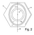
- the threaded bore 12 is arranged in the center of the elliptical shaft 13, which in turn is arranged centrally to hexagonal in this case head 11 in a defined rotational position thereto, in this case with the main axis 60 of the ellipse perpendicular to one of the hexagonal surfaces of the hexagonal head eleventh ,
- both the pressing contour 2 and the smaller punching contour 1 are each formed elliptical and concentric with each other.
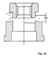
- the die diameter 104 is also shown, ie the inner diameter with which the die 100 supports the metal sheet 21 during the pressing in of the punching nut.
- this die diameter of the shape of the punching contour 1 is also elliptical adjusted and extends in this case between the punching contour 1 and the larger pressing contour 2 with qualitatively identical shape and in the same rotational position, so that when dipping the punch nut, as in Figure 1c represented, with respect to the die diameter 104 slightly smaller punching contour 1 can dip something into the die.
- FIG. 3 shows other non-circular outer contours of the shaft portion 13, which do not illustrate the invention.
- the outer contour is approximately square, ie formed of four polygonal surfaces 15, which are rounded at the edges merge into each other.
- the individual polygon surfaces 15 of the square are viewed in the axial direction 10 as in FIG. 3a shown slightly concave.
- An analogous form has the die contour 104.
- FIG. 3b two different shank shapes 13 are shown with respect to the cross section:
- the shaft 13 is also polygonal, in this case consisting of six equal polygon surfaces 15, in the rotational position symmetrical to the hexagonal head 11 of the punch nut.
- the non-circular contour of the shaft 13 is designed in a ring-shaped annular shape, d. H. with radially outward bulge and in between indentations inwards.
- the shape of the punching contour 1 is the same as that of the pressing contours 2, so that these two diameters are at a constant distance from each other.
- the pressing contour 2 can also have a different spacing and thus a slightly different shape than the punching contour 1.
- the shape of the die diameter 104 is in each case the same as that of the punching contour 1 and, with regard to the size of this contour, lies between the punching contour 1 and the pressing contour 2.
- the non-circular outer contour of the shaft 13 is arranged centrally to the head 11 and the threaded bore 12 in turn centrally within the punching contour 1 or press contour. 2
- non-circular contour of the shaft 13 is formed by polygonal surfaces 15, they do not go to the free end face 8 of the shaft part 13, since the largest diameter of the shaft portion 13 is not the punching contour 1 at the front free end, so the end face 8, but a contrasted, larger press contour 2.
- the polygon surfaces 15 run in the region of the pressing bevel 5 between the punching contour 1 and the pressing contour 2, whereby the pressing contour 2 with respect to the circumference a polygonal contour results, the punching contour 1, however, a round contour.
- a concave configuration of the polygon surfaces 15 is drawn in each case in the left half of the image and indeed formed a cavity when viewed in the axial direction 10 and also a cavity when viewed in the tangential direction is possible, which of course can be combined. It shows Fig. 4 in an enlarged view on the basis of an edge 4 between two polygonal surfaces 15 the effect of this concave formation:
- Fig. 4 a shows plane polygon surfaces 15 according to the prior art, which meet at an edge 4.
- the force 29 engages in the circumferential direction, ie in the direction of the tangential to the hatched circle shown by dashed lines around the polygonal shaft 13 on the nut, and thus presses under a wedge angle 28 against especially the edge regions of the polygon surfaces 15th
- Fig. 4 a shows that, depending on the size of the enveloping circle and the number of polygon surfaces, this wedge angle 28 is very low, and thus a strong wedge effect occurs, which can cause a release of this form-fitting connection with time.
- Fig. 4 c shows one as opposed to Fig. 4 b no longer arcuate design of the concave polygon surface, but a composite of straight sections cavity, so that an equal wedge angle 28 with significantly lower radial depth 31 'can be achieved, which is preferable especially for hard and brittle sheets.
- Fig. 1b shows, punching the smaller punching contour 1 primarily the slug 19, by him - as above all Fig. 1 c shows - shears against the die diameter 104.
- the press contour 2 further in the press-in direction enlarges the press-in opening by displacing the surrounding sheet metal material, However, the die 100 is no longer reached, since their end faces, in particular the bulge 107 present there, are no longer reached at the end of the press-in movement of this pressing contour 2 as a rule.
- the undercut is preferably not continued to the outer periphery, but is before reaching the outer edge in an outer slope 7 on.
- the thus offset from the outer edge inwardly elevation 16 runs at a non-round outer contour of the head 11, as in the right half of Fig. 2 shown, also out of round and already results in a rotationally fixed, positive connection with respect to the sheet.
- FIG. 5 shows a design of the entire device in a longitudinal section analogous to Figure 1 c with further improvements:
- annular groove 32 is arranged in the shaft part 13 of the punching nut in the outer circumference, which here has an arcuate, d. H. semicircular, cross-section and at least the outermost projecting portions, the edges 4 of the shaft portion 13 cuts through, and preferably circumferentially throughout the shaft portion 13 is present.
- the die 200 pressing the punching nut in the direction of the die 100 is shown, which in this case has an annular flange 201 running around the punching nut on the outside.
- This annular flange 201 is used to improve the leadership of the punching nut, but above all the axial length of the annular flange 201 in relation to the axial length punching nut and in particular their head part 11 is chosen so that at the correct Einpresstiefe the mother in the plate 21 of the annular flange 201 is also already imprinted in the top of the sheet 21 and leaves there a marking embossing 300.
- a cone 202 may protrude against the punch nut for engagement with the bevel of the internal thread of the punch nut, which also facilitates the guidance and centering of the nut.
- the inner circumference of the annular flange 201 is formed in accordance with the outer contour of the head portion of the punch nut, for example, with a hexagon socket 203 at a hexagonal head of the punch nut.
- the left half of the figure shows the state shortly before, which is evident in that the bulge 107 of the die has not yet completely impressed in the sheet 21 and thus the flow of the sheet 21 is not yet completed.
Landscapes
- Engineering & Computer Science (AREA)
- General Engineering & Computer Science (AREA)
- Mechanical Engineering (AREA)
- Punching Or Piercing (AREA)
- Forging (AREA)
- Perforating, Stamping-Out Or Severing By Means Other Than Cutting (AREA)
- Automatic Assembly (AREA)
Claims (10)
- Écrou embouti non circulaire présentant une tête (11) et, en face d'elle, une queue (13) plus étroite en retrait autour d'un épaulement (9) périphérique, sachant que la queue (13) présente un contour embouti (1) non circulaire, caractérisé en ce que la queue (13) présente une géométrie extérieure ovale, sachant que la tête (11) possède un contour extérieur polygonal ou circulaire.
- Écrou embouti non circulaire selon la revendication 1, caractérisé en ce que la queue (13) est de géométrie elliptique.
- Écrou embouti non circulaire selon la revendication 2, caractérisé en ce que la queue (13) présente un contour matricé (2) de configuration elliptique agencé concentriquement au contour embouti (1).
- Écrou embouti non circulaire selon la revendication 3, caractérisé en ce que la longueur axiale du chanfrein (5) matricé situé entre le contour matrice (2) et le contour embouti (1) est comprise entre 5 et 25 %, en particulier entre 8 et 15 % de la longueur axiale de la queue (13).
- Écrou embouti non circulaire selon l'une des revendications précédentes, caractérisé ce qu'une contre dépouille (14) descendant en biais vers l'extérieur depuis la queue (13) aboutit avant le diamètre extérieur de la tête (11) et devient un chanfrein (7) extérieur augmentant en direction de l'extérieur.
- Écrou embouti non circulaire selon la revendication 5, caractérisé en ce que l'étendue radiale du chanfrein extérieur (7) est comprise entre 10 et 30 %, en particulier entre 15 et 25 % de l'étendue radiale de l'épaulement (9).
- Écrou embouti non circulaire selon la revendication 5 ou 6, caractérisé en ce que l'angle d'inclinaison du chanfrein extérieur (7) en face du plan transversal par rapport au sens axial (10) est compris entre 10 et 30°, en particulier entre 15 et 25°.
- Écrou embouti non circulaire selon l'une des revendications précédentes, caractérisé en ce que l'épaulement (9) relativement au sens axial (10) n'est pas non plus une surface à symétrie de révolution lorsque la tête (11) présente un diamètre extérieur circonférentiel, mais une surface ondulée ou dentée dans le sens de circulation.
- Écrou embouti non circulaire selon l'une des revendications précitées, caractérisé en ce que sur la périphérie de la queue (13) ont été ménagées une ou plusieurs gorges annulaires en partie périphériques.
- Écrou embouti non circulaire selon l'une des revendications précédentes, caractérisé en ce que l'écrou embouti possède un orifice de passage central sans parois intérieures pour interagir avec une vis autotaraudeuse.
Applications Claiming Priority (1)
| Application Number | Priority Date | Filing Date | Title |
|---|---|---|---|
| DE200710022624 DE102007022624A1 (de) | 2007-05-15 | 2007-05-15 | Unrunde Stanzmutter |
Publications (3)
| Publication Number | Publication Date |
|---|---|
| EP1995475A2 EP1995475A2 (fr) | 2008-11-26 |
| EP1995475A3 EP1995475A3 (fr) | 2011-12-07 |
| EP1995475B1 true EP1995475B1 (fr) | 2014-01-08 |
Family
ID=39666154
Family Applications (1)
| Application Number | Title | Priority Date | Filing Date |
|---|---|---|---|
| EP20080155345 Active EP1995475B1 (fr) | 2007-05-15 | 2008-04-29 | Ecrou embouti non circulaire |
Country Status (3)
| Country | Link |
|---|---|
| EP (1) | EP1995475B1 (fr) |
| DE (1) | DE102007022624A1 (fr) |
| ES (1) | ES2456332T3 (fr) |
Families Citing this family (2)
| Publication number | Priority date | Publication date | Assignee | Title |
|---|---|---|---|---|
| JP7070034B2 (ja) * | 2018-04-25 | 2022-05-18 | 横浜ゴム株式会社 | スタッドピン、及びスタッドタイヤ |
| DE102023112483A1 (de) * | 2023-05-11 | 2024-11-14 | Profil Verbindungstechnik Gmbh & Co. Kg | Funktionselement |
Family Cites Families (10)
| Publication number | Priority date | Publication date | Assignee | Title |
|---|---|---|---|---|
| GB1004562A (en) * | 1962-03-02 | 1965-09-15 | Walsh John & Co Inserts Ltd | Improvements in fasteners or bushes for anchoring in sheet material or the like |
| US3399705A (en) | 1966-02-10 | 1968-09-03 | Lamson & Sessions Co | Self-staking insert |
| GB1205605A (en) * | 1966-09-22 | 1970-09-16 | Bultafabriks Aktiebolaget | A pierce nut |
| US3878598A (en) * | 1972-03-27 | 1975-04-22 | Multifastener Corp | Method of forming a nut and panel assembly |
| DE3626466A1 (de) | 1986-08-05 | 1988-02-18 | Lamson & Sessions Gmbh | Einpressmutter |
| US6220804B1 (en) * | 1999-03-24 | 2001-04-24 | R B & W Corporation | Self-piercing clinch nut |
| US6491487B1 (en) * | 2001-07-19 | 2002-12-10 | Fabristeel Products, Inc. | Double-ended self-attaching stud |
| JP2005226788A (ja) * | 2004-02-16 | 2005-08-25 | Shinjo Mfg Co Ltd | ピアスナット |
| DE102004020676A1 (de) * | 2004-04-28 | 2005-11-24 | Profil-Verbindungstechnik Gmbh & Co. Kg | Verfahren und Vorrichtung zur Anbringung eines Befestigungselements an ein Bauteil, insbesondere an ein Blechteil |
| US7152297B2 (en) * | 2004-06-02 | 2006-12-26 | Whitesell International Corporation | Self-attaching female fastener, die set and method of attachment |
-
2007
- 2007-05-15 DE DE200710022624 patent/DE102007022624A1/de not_active Withdrawn
-
2008
- 2008-04-29 EP EP20080155345 patent/EP1995475B1/fr active Active
- 2008-04-29 ES ES08155345T patent/ES2456332T3/es active Active
Also Published As
| Publication number | Publication date |
|---|---|
| ES2456332T3 (es) | 2014-04-22 |
| EP1995475A3 (fr) | 2011-12-07 |
| EP1995475A2 (fr) | 2008-11-26 |
| DE102007022624A1 (de) | 2008-11-27 |
Similar Documents
| Publication | Publication Date | Title |
|---|---|---|
| EP1803192B1 (fr) | Cosse de cable comprenant un ecrou ou un element fonctionnel, procede de production d'une telle cosse de cable et ecrou | |
| DE69630901T2 (de) | Verfahren zum einpressen eines verbindungselementes, bolzen, nietmatrize und komponentenanordnung | |
| DE69419890T2 (de) | Vorrichtung zur Herstellung selbststanzender Muttern | |
| EP2479442B1 (fr) | Elément de fonction sous la forme d'un élément de compression | |
| EP1918596B1 (fr) | Rivet aveugle et son utilisation | |
| EP1557574B1 (fr) | Ecrou à rivet aveugle | |
| EP2809497B1 (fr) | Tête d'expansion pour élargisseurs et élargisseur comprenant ladite tête d'expansion | |
| EP0993902A2 (fr) | Procédé pour attacher un élément fonctionnel, matrice, élément fonctionnel et ensemble de montage | |
| DE1811695B2 (de) | Schraube | |
| WO1982002579A1 (fr) | Ecrou encastrable | |
| EP2224143B1 (fr) | Ecrou, raccordement de vis, connexion de profilé, ainsi que procédé de fabrication d'un écrou | |
| EP0759510A1 (fr) | Corps creux, matrice pour le corps creux, méthode pour la fixation d'un corps creux sur un élément en forme plate et ensemble de montage | |
| DE102009012243B4 (de) | Stanzmutter, Stanzmutter-Vorrichtung und Stanzmutter-Blechverbindung | |
| EP1923585A2 (fr) | Écrou embouti | |
| EP1995475B1 (fr) | Ecrou embouti non circulaire | |
| EP1923584A2 (fr) | Ecrou embouti | |
| EP1923583B1 (fr) | Ecrou embouti | |
| DE102015221765B3 (de) | Zylinderanordnung mit einem Boden und Vorrichtung zur Herstellung einer Formschlussverbindung zwischen dem Boden und einem Zylinder | |
| EP1591676B1 (fr) | Elément rapporté à enfoncement automatique pour tôle | |
| DE202007019237U1 (de) | Stanzmutter | |
| EP4431415B1 (fr) | Ensemble comprenant un récipient extérieur avec un récipient intérieur disposé dans celui-ci et procédé d'ouverture et de fabrication d'un ensemble | |
| EP3564545A1 (fr) | Composant d'assemblage comprenant un composant et d'un élément doté d'une partie de tête et d'un col disposé sur un côté de la partie de tête ainsi que son procédé de fabrication | |
| WO2011029616A2 (fr) | Tête de fermeture pour visser des bouchons à vis | |
| DE102004052053B4 (de) | Verfahren zum Befestigen eines Bauteils in einer Baukomponente | |
| DE102023208982A1 (de) | Einpresselement, Verfahren zur Ausbildung einer Einpressverbindung sowie Einpressverbindung |
Legal Events
| Date | Code | Title | Description |
|---|---|---|---|
| PUAI | Public reference made under article 153(3) epc to a published international application that has entered the european phase |
Free format text: ORIGINAL CODE: 0009012 |
|
| AK | Designated contracting states |
Kind code of ref document: A2 Designated state(s): AT BE BG CH CY CZ DE DK EE ES FI FR GB GR HR HU IE IS IT LI LT LU LV MC MT NL NO PL PT RO SE SI SK TR |
|
| AX | Request for extension of the european patent |
Extension state: AL BA MK RS |
|
| PUAL | Search report despatched |
Free format text: ORIGINAL CODE: 0009013 |
|
| AK | Designated contracting states |
Kind code of ref document: A3 Designated state(s): AT BE BG CH CY CZ DE DK EE ES FI FR GB GR HR HU IE IS IT LI LT LU LV MC MT NL NO PL PT RO SE SI SK TR |
|
| AX | Request for extension of the european patent |
Extension state: AL BA MK RS |
|
| RIC1 | Information provided on ipc code assigned before grant |
Ipc: F16B 37/06 20060101AFI20111028BHEP |
|
| 17P | Request for examination filed |
Effective date: 20120605 |
|
| AKX | Designation fees paid |
Designated state(s): AT BE BG CH CY CZ DE DK EE ES FI FR GB GR HR HU IE IS IT LI LT LU LV MC MT NL NO PL PT RO SE SI SK TR |
|
| 17Q | First examination report despatched |
Effective date: 20120723 |
|
| GRAP | Despatch of communication of intention to grant a patent |
Free format text: ORIGINAL CODE: EPIDOSNIGR1 |
|
| INTG | Intention to grant announced |
Effective date: 20131009 |
|
| GRAS | Grant fee paid |
Free format text: ORIGINAL CODE: EPIDOSNIGR3 |
|
| GRAA | (expected) grant |
Free format text: ORIGINAL CODE: 0009210 |
|
| AK | Designated contracting states |
Kind code of ref document: B1 Designated state(s): AT BE BG CH CY CZ DE DK EE ES FI FR GB GR HR HU IE IS IT LI LT LU LV MC MT NL NO PL PT RO SE SI SK TR |
|
| REG | Reference to a national code |
Ref country code: GB Ref legal event code: FG4D Free format text: NOT ENGLISH |
|
| REG | Reference to a national code |
Ref country code: CH Ref legal event code: EP |
|
| REG | Reference to a national code |
Ref country code: IE Ref legal event code: FG4D Free format text: LANGUAGE OF EP DOCUMENT: GERMAN |
|
| REG | Reference to a national code |
Ref country code: AT Ref legal event code: REF Ref document number: 648936 Country of ref document: AT Kind code of ref document: T Effective date: 20140215 |
|
| REG | Reference to a national code |
Ref country code: DE Ref legal event code: R096 Ref document number: 502008011183 Country of ref document: DE Effective date: 20140220 |
|
| REG | Reference to a national code |
Ref country code: SE Ref legal event code: TRGR |
|
| REG | Reference to a national code |
Ref country code: ES Ref legal event code: FG2A Ref document number: 2456332 Country of ref document: ES Kind code of ref document: T3 Effective date: 20140422 |
|
| REG | Reference to a national code |
Ref country code: NL Ref legal event code: VDEP Effective date: 20140108 |
|
| REG | Reference to a national code |
Ref country code: LT Ref legal event code: MG4D |
|
| PG25 | Lapsed in a contracting state [announced via postgrant information from national office to epo] |
Ref country code: LT Free format text: LAPSE BECAUSE OF FAILURE TO SUBMIT A TRANSLATION OF THE DESCRIPTION OR TO PAY THE FEE WITHIN THE PRESCRIBED TIME-LIMIT Effective date: 20140108 Ref country code: IS Free format text: LAPSE BECAUSE OF FAILURE TO SUBMIT A TRANSLATION OF THE DESCRIPTION OR TO PAY THE FEE WITHIN THE PRESCRIBED TIME-LIMIT Effective date: 20140508 Ref country code: NO Free format text: LAPSE BECAUSE OF FAILURE TO SUBMIT A TRANSLATION OF THE DESCRIPTION OR TO PAY THE FEE WITHIN THE PRESCRIBED TIME-LIMIT Effective date: 20140408 |
|
| PG25 | Lapsed in a contracting state [announced via postgrant information from national office to epo] |
Ref country code: CY Free format text: LAPSE BECAUSE OF FAILURE TO SUBMIT A TRANSLATION OF THE DESCRIPTION OR TO PAY THE FEE WITHIN THE PRESCRIBED TIME-LIMIT Effective date: 20140108 Ref country code: PT Free format text: LAPSE BECAUSE OF FAILURE TO SUBMIT A TRANSLATION OF THE DESCRIPTION OR TO PAY THE FEE WITHIN THE PRESCRIBED TIME-LIMIT Effective date: 20140508 Ref country code: NL Free format text: LAPSE BECAUSE OF FAILURE TO SUBMIT A TRANSLATION OF THE DESCRIPTION OR TO PAY THE FEE WITHIN THE PRESCRIBED TIME-LIMIT Effective date: 20140108 Ref country code: FI Free format text: LAPSE BECAUSE OF FAILURE TO SUBMIT A TRANSLATION OF THE DESCRIPTION OR TO PAY THE FEE WITHIN THE PRESCRIBED TIME-LIMIT Effective date: 20140108 |
|
| PG25 | Lapsed in a contracting state [announced via postgrant information from national office to epo] |
Ref country code: LV Free format text: LAPSE BECAUSE OF FAILURE TO SUBMIT A TRANSLATION OF THE DESCRIPTION OR TO PAY THE FEE WITHIN THE PRESCRIBED TIME-LIMIT Effective date: 20140108 Ref country code: HR Free format text: LAPSE BECAUSE OF FAILURE TO SUBMIT A TRANSLATION OF THE DESCRIPTION OR TO PAY THE FEE WITHIN THE PRESCRIBED TIME-LIMIT Effective date: 20140108 |
|
| REG | Reference to a national code |
Ref country code: DE Ref legal event code: R097 Ref document number: 502008011183 Country of ref document: DE |
|
| PG25 | Lapsed in a contracting state [announced via postgrant information from national office to epo] |
Ref country code: RO Free format text: LAPSE BECAUSE OF FAILURE TO SUBMIT A TRANSLATION OF THE DESCRIPTION OR TO PAY THE FEE WITHIN THE PRESCRIBED TIME-LIMIT Effective date: 20140108 Ref country code: DK Free format text: LAPSE BECAUSE OF FAILURE TO SUBMIT A TRANSLATION OF THE DESCRIPTION OR TO PAY THE FEE WITHIN THE PRESCRIBED TIME-LIMIT Effective date: 20140108 Ref country code: EE Free format text: LAPSE BECAUSE OF FAILURE TO SUBMIT A TRANSLATION OF THE DESCRIPTION OR TO PAY THE FEE WITHIN THE PRESCRIBED TIME-LIMIT Effective date: 20140108 Ref country code: CZ Free format text: LAPSE BECAUSE OF FAILURE TO SUBMIT A TRANSLATION OF THE DESCRIPTION OR TO PAY THE FEE WITHIN THE PRESCRIBED TIME-LIMIT Effective date: 20140108 |
|
| PLBE | No opposition filed within time limit |
Free format text: ORIGINAL CODE: 0009261 |
|
| STAA | Information on the status of an ep patent application or granted ep patent |
Free format text: STATUS: NO OPPOSITION FILED WITHIN TIME LIMIT |
|
| PG25 | Lapsed in a contracting state [announced via postgrant information from national office to epo] |
Ref country code: SK Free format text: LAPSE BECAUSE OF FAILURE TO SUBMIT A TRANSLATION OF THE DESCRIPTION OR TO PAY THE FEE WITHIN THE PRESCRIBED TIME-LIMIT Effective date: 20140108 Ref country code: PL Free format text: LAPSE BECAUSE OF FAILURE TO SUBMIT A TRANSLATION OF THE DESCRIPTION OR TO PAY THE FEE WITHIN THE PRESCRIBED TIME-LIMIT Effective date: 20140108 Ref country code: MC Free format text: LAPSE BECAUSE OF FAILURE TO SUBMIT A TRANSLATION OF THE DESCRIPTION OR TO PAY THE FEE WITHIN THE PRESCRIBED TIME-LIMIT Effective date: 20140108 Ref country code: LU Free format text: LAPSE BECAUSE OF FAILURE TO SUBMIT A TRANSLATION OF THE DESCRIPTION OR TO PAY THE FEE WITHIN THE PRESCRIBED TIME-LIMIT Effective date: 20140429 |
|
| REG | Reference to a national code |
Ref country code: CH Ref legal event code: PL |
|
| 26N | No opposition filed |
Effective date: 20141009 |
|
| GBPC | Gb: european patent ceased through non-payment of renewal fee |
Effective date: 20140429 |
|
| REG | Reference to a national code |
Ref country code: DE Ref legal event code: R097 Ref document number: 502008011183 Country of ref document: DE Effective date: 20141009 |
|
| REG | Reference to a national code |
Ref country code: IE Ref legal event code: MM4A |
|
| PG25 | Lapsed in a contracting state [announced via postgrant information from national office to epo] |
Ref country code: LI Free format text: LAPSE BECAUSE OF NON-PAYMENT OF DUE FEES Effective date: 20140430 Ref country code: GB Free format text: LAPSE BECAUSE OF NON-PAYMENT OF DUE FEES Effective date: 20140429 Ref country code: CH Free format text: LAPSE BECAUSE OF NON-PAYMENT OF DUE FEES Effective date: 20140430 |
|
| PG25 | Lapsed in a contracting state [announced via postgrant information from national office to epo] |
Ref country code: IE Free format text: LAPSE BECAUSE OF NON-PAYMENT OF DUE FEES Effective date: 20140429 |
|
| PG25 | Lapsed in a contracting state [announced via postgrant information from national office to epo] |
Ref country code: SI Free format text: LAPSE BECAUSE OF FAILURE TO SUBMIT A TRANSLATION OF THE DESCRIPTION OR TO PAY THE FEE WITHIN THE PRESCRIBED TIME-LIMIT Effective date: 20140108 |
|
| REG | Reference to a national code |
Ref country code: AT Ref legal event code: MM01 Ref document number: 648936 Country of ref document: AT Kind code of ref document: T Effective date: 20140429 |
|
| PG25 | Lapsed in a contracting state [announced via postgrant information from national office to epo] |
Ref country code: AT Free format text: LAPSE BECAUSE OF NON-PAYMENT OF DUE FEES Effective date: 20140429 |
|
| PG25 | Lapsed in a contracting state [announced via postgrant information from national office to epo] |
Ref country code: MT Free format text: LAPSE BECAUSE OF FAILURE TO SUBMIT A TRANSLATION OF THE DESCRIPTION OR TO PAY THE FEE WITHIN THE PRESCRIBED TIME-LIMIT Effective date: 20140108 |
|
| REG | Reference to a national code |
Ref country code: FR Ref legal event code: PLFP Year of fee payment: 9 |
|
| PG25 | Lapsed in a contracting state [announced via postgrant information from national office to epo] |
Ref country code: BG Free format text: LAPSE BECAUSE OF FAILURE TO SUBMIT A TRANSLATION OF THE DESCRIPTION OR TO PAY THE FEE WITHIN THE PRESCRIBED TIME-LIMIT Effective date: 20140108 |
|
| PG25 | Lapsed in a contracting state [announced via postgrant information from national office to epo] |
Ref country code: GR Free format text: LAPSE BECAUSE OF FAILURE TO SUBMIT A TRANSLATION OF THE DESCRIPTION OR TO PAY THE FEE WITHIN THE PRESCRIBED TIME-LIMIT Effective date: 20140409 |
|
| PG25 | Lapsed in a contracting state [announced via postgrant information from national office to epo] |
Ref country code: HU Free format text: LAPSE BECAUSE OF FAILURE TO SUBMIT A TRANSLATION OF THE DESCRIPTION OR TO PAY THE FEE WITHIN THE PRESCRIBED TIME-LIMIT; INVALID AB INITIO Effective date: 20080429 Ref country code: BE Free format text: LAPSE BECAUSE OF FAILURE TO SUBMIT A TRANSLATION OF THE DESCRIPTION OR TO PAY THE FEE WITHIN THE PRESCRIBED TIME-LIMIT Effective date: 20140430 |
|
| REG | Reference to a national code |
Ref country code: FR Ref legal event code: PLFP Year of fee payment: 10 |
|
| REG | Reference to a national code |
Ref country code: FR Ref legal event code: PLFP Year of fee payment: 11 |
|
| PGFP | Annual fee paid to national office [announced via postgrant information from national office to epo] |
Ref country code: DE Payment date: 20210430 Year of fee payment: 14 Ref country code: IT Payment date: 20210428 Year of fee payment: 14 Ref country code: FR Payment date: 20210429 Year of fee payment: 14 |
|
| PGFP | Annual fee paid to national office [announced via postgrant information from national office to epo] |
Ref country code: SE Payment date: 20210429 Year of fee payment: 14 Ref country code: TR Payment date: 20210524 Year of fee payment: 14 Ref country code: ES Payment date: 20210519 Year of fee payment: 14 |
|
| REG | Reference to a national code |
Ref country code: DE Ref legal event code: R119 Ref document number: 502008011183 Country of ref document: DE |
|
| REG | Reference to a national code |
Ref country code: SE Ref legal event code: EUG |
|
| PG25 | Lapsed in a contracting state [announced via postgrant information from national office to epo] |
Ref country code: SE Free format text: LAPSE BECAUSE OF NON-PAYMENT OF DUE FEES Effective date: 20220430 Ref country code: FR Free format text: LAPSE BECAUSE OF NON-PAYMENT OF DUE FEES Effective date: 20220430 Ref country code: DE Free format text: LAPSE BECAUSE OF NON-PAYMENT OF DUE FEES Effective date: 20221103 |
|
| PG25 | Lapsed in a contracting state [announced via postgrant information from national office to epo] |
Ref country code: IT Free format text: LAPSE BECAUSE OF NON-PAYMENT OF DUE FEES Effective date: 20220429 |
|
| REG | Reference to a national code |
Ref country code: ES Ref legal event code: FD2A Effective date: 20230602 |
|
| PG25 | Lapsed in a contracting state [announced via postgrant information from national office to epo] |
Ref country code: ES Free format text: LAPSE BECAUSE OF NON-PAYMENT OF DUE FEES Effective date: 20220430 |