EP1995554A2 - Dispositif d'étalonnage de réseau bidimensionnel, son procédé, programme et support d'enregistrement - Google Patents
Dispositif d'étalonnage de réseau bidimensionnel, son procédé, programme et support d'enregistrement Download PDFInfo
- Publication number
- EP1995554A2 EP1995554A2 EP08156718A EP08156718A EP1995554A2 EP 1995554 A2 EP1995554 A2 EP 1995554A2 EP 08156718 A EP08156718 A EP 08156718A EP 08156718 A EP08156718 A EP 08156718A EP 1995554 A2 EP1995554 A2 EP 1995554A2
- Authority
- EP
- European Patent Office
- Prior art keywords
- measurement
- equations
- marks
- artifact
- error
- Prior art date
- Legal status (The legal status is an assumption and is not a legal conclusion. Google has not performed a legal analysis and makes no representation as to the accuracy of the status listed.)
- Withdrawn
Links
- 238000000034 method Methods 0.000 title claims description 32
- 238000005259 measurement Methods 0.000 claims abstract description 476
- 238000004364 calculation method Methods 0.000 claims description 30
- 230000014509 gene expression Effects 0.000 claims description 12
- 238000004590 computer program Methods 0.000 claims 1
- 238000012937 correction Methods 0.000 description 18
- 239000011159 matrix material Substances 0.000 description 17
- 239000013598 vector Substances 0.000 description 11
- 230000000694 effects Effects 0.000 description 6
- 230000008569 process Effects 0.000 description 6
- 230000001419 dependent effect Effects 0.000 description 5
- 238000003384 imaging method Methods 0.000 description 5
- 238000012545 processing Methods 0.000 description 5
- 238000000354 decomposition reaction Methods 0.000 description 4
- 238000013519 translation Methods 0.000 description 4
- 230000010365 information processing Effects 0.000 description 3
- 238000012935 Averaging Methods 0.000 description 2
- 238000012986 modification Methods 0.000 description 2
- 230000004048 modification Effects 0.000 description 2
- 230000003287 optical effect Effects 0.000 description 2
- 230000009897 systematic effect Effects 0.000 description 2
- 235000010678 Paulownia tomentosa Nutrition 0.000 description 1
- 240000002834 Paulownia tomentosa Species 0.000 description 1
- 238000013459 approach Methods 0.000 description 1
- 230000015556 catabolic process Effects 0.000 description 1
- 230000003247 decreasing effect Effects 0.000 description 1
- 238000006731 degradation reaction Methods 0.000 description 1
- 238000009795 derivation Methods 0.000 description 1
- 238000013461 design Methods 0.000 description 1
- 230000002542 deteriorative effect Effects 0.000 description 1
- 238000011156 evaluation Methods 0.000 description 1
- 230000006872 improvement Effects 0.000 description 1
- 230000007246 mechanism Effects 0.000 description 1
- 238000005457 optimization Methods 0.000 description 1
- 230000000644 propagated effect Effects 0.000 description 1
- 238000011160 research Methods 0.000 description 1
- 230000004044 response Effects 0.000 description 1
- 230000009466 transformation Effects 0.000 description 1
Images








Classifications
-
- G—PHYSICS
- G01—MEASURING; TESTING
- G01B—MEASURING LENGTH, THICKNESS OR SIMILAR LINEAR DIMENSIONS; MEASURING ANGLES; MEASURING AREAS; MEASURING IRREGULARITIES OF SURFACES OR CONTOURS
- G01B21/00—Measuring arrangements or details thereof, where the measuring technique is not covered by the other groups of this subclass, unspecified or not relevant
- G01B21/02—Measuring arrangements or details thereof, where the measuring technique is not covered by the other groups of this subclass, unspecified or not relevant for measuring length, width, or thickness
- G01B21/04—Measuring arrangements or details thereof, where the measuring technique is not covered by the other groups of this subclass, unspecified or not relevant for measuring length, width, or thickness by measuring coordinates of points
- G01B21/042—Calibration or calibration artifacts
Definitions
- the present invention relates to a two-dimensional calibrating device. More specifically, it relates to a two-dimensional lattice calibrating device that calibrates a mark position of an artifact (e.g. square lattice) as a standard gauge.
- the present invention also relates to a two-dimensional lattice calibrating method, two-dimensional lattice calibrating program and a recording medium storing the program.
- block-shaped and plate-shaped standard gauges have been used for calibrating a precise measuring instrument.
- standard gauges those having square-lattice marks (including measuring point, center of a ball and the like) such as a ball plate and a grid plate are called as artifacts, which are used as a standard mainly for calibrating a coordinate measuring machine and a vision measuring machine. Accordingly, the position of the marks has to be sufficiently accurately positioned. However, it accompanies a great difficulty to produce a highly accurate artifact. Accordingly, after producing an artifact, a deviation between the position of the mark and a nominal position of the mark is measured, calculated and calibrated. In order to calibrate a ball plate, for example, inverse method has been proposed.
- a ball plate is rotated by 180 degrees around x, y and z axes respectively, where total four measurements are conducted to obtain measurement values in accordance with a rank of simultaneous equations for calibration ( Figs. 23A to 23D ).
- the inverse method requires that an artifact can be measured from a backside thereof. Accordingly, when it is difficult for an artifact to be measured from a backside, calibration using the inverse method is impractical. For instance, a grid plate (an artifact for vision measuring machine) cannot be highly calibrated by the inverse method, since the condition varies between top-side measurement and backside measurement of the grid plate.
- An object of the present invention is to provide a two-dimensional lattice calibrating device, a two-dimensional lattice calibrating method, a two-dimensional lattice calibrating program and a recording medium.
- a two-dimensional lattice calibrating device includes: a measuring unit that measures positions of a plurality of marks within a plane of an artifact as a standard gauge, the positions of the plurality of marks being measured per a plurality of measurement dispositions in which at least a part of the plurality of marks is superposed; a coordinate setting unit in which a coordinate relational equation is set in advance, the coordinate relational equation representing a relationship between a measurement coordinate system of the measuring unit and an artifact coordinate system for specifying the positions of the plurality of marks on the artifact for each of the plurality of measurement dispositions; a simultaneous-equations generating unit that generates simultaneous equations for acquiring deviations of the plurality of marks using a coordinate relational equation and a conditional equation that sets a coordinate
- conditional equation for setting the coordinate axis of the artifact coordinate system is a least-squares line equation obtained under a condition that the deviation between the measurement value of the plurality of marks and a designed value becomes minimum, the least-squares line being set as the coordinate axis of the artifact.
- the artifact is, for instance, a square lattice (grid plate) and a ball plate.
- the measurement points of the artifact are referred to as marks.
- the designed value (nominal value) is a value based on a design of the position of the marks.
- the value corrected by the correction value may be used as the correction value.
- the actual position is a value adding the deviation to the designed value.
- the least-squares conditional equation includes an equation prerequisite for applying the least-squares method, formulae for approximating a linear line obtained by the least-squares method and the like.
- the conditional equation for acquiring a linear line that minimize the deviation D of the entirety or a part of the marks is the least-squares line.
- the simultaneous equations are generated by, for instance, reading out the coordinate relational equations and applying the measurement values and the designed values.
- a normal equation may be solved by matrix calculation, or a Jacobian matrix may be acquired to conduct collective arithmetic calculation thereon after QR-decomposition and the like.
- the coordinate relational equations that represent the relationship between the measurement coordinate system of the measuring unit and the artifact coordinate system that identifies the mark positions of the artifact for each of the measurement dispositions are set in the coordinate setting unit in advance.
- the simultaneous-equations generating unit generates the simultaneous equations that acquire the deviation of actual position the respective marks from the designed value with the use of the least-squares conditional equation and the coordinate relational equation.
- the simultaneous-equations calculating unit solves the simultaneous equations while setting the least-squares lines as the coordinate axes to level the values of the deviation D and to separate the relationship between the respective coordinates and the deviation.
- the obtained measurement value may vary according to the dispositions in measuring the marks even when the same marks are measured.
- the coordinate axes may be set so that the deviation between the plurality of measurement values obtained for the same marks is minimized.
- the coordinate relational equation may include: an origin error An that is a deviation of an origin and a setting rotation error ⁇ n as setting errors that are different per each of measurements under the respective measurement dispositions n; and a squareness error ⁇ of the artifact coordinate system and deviations ⁇ , ⁇ from the designed value as errors that are common to each of the measurements
- the least-squares line equation may include a first conditional equation for minimizing average values of values adding the designed value and the deviation and a second conditional equation for minimizing averages of the deviations ⁇ , ⁇
- the simultaneous-equations calculating unit may correct the designed value based on the squareness error ⁇ of the artifact coordinate system calculated by the simultaneous-equations calculating unit and the deviations ⁇ , ⁇ to repeatedly calculate the least-squares line.
- the coordinate relational equation can define the setting error independently from the deviation. Further, since the simultaneous-equations calculating unit repeatedly calculates the least-squares line to be the coordinate axes of the artifact coordinates, so that the deviation independent of the setting error and the measurement error can be accurately calculated.
- the coordinate relational equation includes a measurement error e, a squareness error ⁇ of the measurement coordinate system and a scale error ⁇ b of the measurement coordinate system as errors that are common to each of the measurements
- the least-squares line equation includes the second conditional equation that minimizes the average of the deviations ⁇ , ⁇ and an average of the measurement error e corrected by the scale error ⁇ b of the measurement coordinate system
- the simultaneous-equations calculating unit calibrates the deviations ⁇ , ⁇ simultaneously with calibrating the scale error ⁇ b of the measuring unit and the squareness error ⁇ of the measurement coordinate system.
- the error (measurement error, squareness error and scale error) of the measuring unit can be defined separately from the deviation by the coordinate relational equation and the simultaneous-equations calculating unit can calculate the deviation independent of the errors of the measuring unit.
- the measuring unit conducts a first measurement after disposing the artifact in a first measurement disposition where the coordinate axis and point sequence of the marks are aligned, the measuring unit conducts a second measurement after rotating the artifact in-plane by ninety degrees relative to the first measurement disposition as a second measurement disposition around a centroid position substantially identical with the first measurement disposition, the measuring unit conducts a third measurement after rotating the artifact in a plane by one-hundred eighty degrees relative to the first measurement disposition as a third measurement disposition around the centroid position substantially identical with the first measurement disposition, and the measuring unit conducts a fourth measurement after translating the artifact by a distance corresponding to an interval of the marks relative to the first measurement disposition as a fourth measurement disposition
- the disposition rotated in-plane is preferably a disposition in which the artifact is rotated by a predetermined angle around the center of the artifact as the origin while the plane including the marks of the artifact is not displaced in normal line direction thereof.
- the point sequence direction of the marks is row and column direction of the marks in a square lattice.
- a two-dimensional lattice calibrating method includes: a measuring step that measures positions of a plurality of marks within a plane of an artifact as a standard gauge, the positions of the plurality of marks being measured for each of a plurality of measurement dispositions in which at least a part of the plurality of marks is superposed; a coordinate setting step in which a coordinate relational equation is set in advance, the coordinate relational equation representing a relationship between a measurement coordinate system of the measuring unit and an artifact coordinate system for specifying the positions of the plurality of marks on the artifact for each of the plurality of measurement dispositions, the coordinate setting step being performed before or after the measuring step; a simultaneous equations generating step that generates simultaneous equations for acquiring deviations of the plurality of marks using the coordinate relational equation and a least-squares conditional equation that sets a least-squares line that minimizes a deviation between an actual position of the marks corresponding to the measurement value and a predetermined designed value as a coordinate axis of
- the two-dimensional lattice calibrating device of the invention may be arranged as follows.
- a two-dimensional lattice calibrating device includes: a measuring unit that measures positions of a plurality of marks within a plane of an artifact as a standard gauge, the positions of the plurality of marks being measured per a plurality of measurement dispositions in which at least a part of the plurality of marks is superposed; a storage that stores a measurement value m for each of the measurement in the measurement dispositions, a predetermined arithmetic formula and a nominal value N that is a designed position of the marks; and a computing unit that calculates a deviation in predetermined artifact coordinates between the nominal value M and an actual value L using the measurement value m at predetermined measurement coordinates stored in the storage and the nominal value N according to the predetermined arithmetic formula.
- the artifact coordinates include: coordinate axes that are least-squares lines that minimize the deviation between the actual position and the nominal value of the artifact in x-axis and y-axis directions; and a squareness error ⁇ that is an angular difference between an angle formed by the least-squares lines and a right angle.
- the measurement coordinates include coordinate axes that are least-squares lines that minimize a measurement error e of the measuring unit respectively in the x-axis and y-axis directions and a squareness error ⁇ that is an angular difference between an angle formed by the coordinate axes and a right angle.
- the storage further includes a measurement value storage, a nominal value storage, a coordinate relational equation storage and a least-squares conditional equation storage.
- the measurement value storage stores the measurement value m for each of the measurements.
- the nominal value storage stores the nominal value N that is a designed position of the marks in nominal coordinates having as coordinate axes a x0-axis and a y0-axis that orthogonally cross at an origin of the centroid position of the marks.
- the coordinate relational equation storage that stores relational equations that represent a relationship among: an origin error A of the origins of the artifact coordinates and the measurement coordinates supposing that the actual value L of the marks within the artifact coordinates and the actual value G of the marks within the measurement coordinates are identical; the squareness errors ⁇ , ⁇ of the respective coordinates; a rotation error B according to the setting rotation error ⁇ of the measurement disposition; the nominal value N; the measurement error e; and the measurement value m, which are stored as coordinate relational equations per each of the measurement dispositions.
- the least-squares conditional equation storage stores a least-squares conditional equation that sets coordinate axes of the respective coordinates as least-squares lines.
- the computing unit includes: a simultaneous-equations generating unit that reads out the measurement value m per each of the measurement dispositions and the nominal value N to assign into the coordinate relational equations per each of the measurement dispositions stored in the coordinates relational expression storage and reads out the least-squares conditional equation to generate simultaneous equations for acquiring the deviation D from the nominal value N to the actual position L of the respective marks using the measurement value m; and a simultaneous-equations calculating unit that solves the simultaneous equations generated by the simultaneous-equations generating unit.
- the measurement value m is given by measurement coordinates and the coordinate axes of the measurement coordinates are least-squares lines that minimize the measurement error e, which is specified by the squareness error ⁇ .
- the nominal value and the deviation are given by artifact coordinates and the coordinate axes of the artifact coordinates are least-squares lines that minimize the deviation D, which is specified by the squareness error ⁇ .
- the coordinate relational equation storage stores relational equations that represent a relationship among: an origin error A of the origins of the artifact coordinates and the measurement coordinates supposing that the actual value L of the marks within the artifact coordinates and the actual value G of the marks within the measurement coordinates are identical; the squareness errors ⁇ , ⁇ of the respective coordinates; a rotation error B according to the setting rotation error ⁇ of the measurement disposition; the nominal value N; the measurement error e; and the measurement value m, which are stored as coordinate relational equations per each of the measurement dispositions.
- the coordinate relational equations are formulae that associate ⁇ , ⁇ , e, N and m independent of the measurement dispositions with A and B dependent on the measurement dispositions while separating with each other.
- the simultaneous-equations generating unit generates simultaneous equations by assigning the measurement value and the nominal value into the coordinate relational equations and by reading out the least-squares conditional expression.
- the simultaneous-equations calculating unit solves the simultaneous equations.
- a normal equation may be solved by matrix calculation, or a Jacobian matrix may be acquired to conduct collective arithmetic calculation thereon after QR-decomposition and the like.
- the two-dimensional lattice calibrating device that handles the measurement error achieves the same advantages as the above-described two-dimensional lattice calibrating device.
- the two-dimensional lattice calibrating device can separately and simultaneously acquire the deviation D, the measurement error e, the setting error A and the squareness errors ⁇ and ⁇ . Accordingly, the effect of the setting error A that varies for each of the measurements and the influence of the measurement error by the measuring unit can be separated to calculate the deviation D of the mark position of the artifact and the squareness error ⁇ .
- the coordinate relational equation storage stores the coordinate relational equation approximating the rotation error B with a primary equation
- the simultaneous-equations generating unit conducts addition and subtraction of the squareness errors ⁇ , ⁇ of the respective coordinates and the setting angular error ⁇ for each of the measurement dispositions and reads out the equations for acquiring the rotation error B by the multiplication with the nominal value N per each of the marks from the coordinate relational equation storage to assign the corresponding nominal values N to each of the equations for the measurement values m
- the simultaneous-equations calculating unit solves the simultaneous equations as primary equations.
- the simultaneous-equations calculating unit collectively conducts arithmetic calculation of the simultaneous equations of the coordinates relational equations and the least-squares conditional equation.
- a two-dimensional lattice calibrating program is read by a computer connected with a measuring unit that measures positions of marks provided on a plane of an artifact as a standard gauge, the measuring unit measuring the positions of the marks per each of a plurality of measurement dispositions in which the marks are at least partially superposed, the computer calculating deviations of the marks using measurement values per each of the measurement dispositions, the program operating the computer as a two-dimensional lattice calibrating device that handles the above measurement errors.
- a recording medium stores the two-dimensional lattice calibrating program to install the file of the program in an auxiliary storage (storage unit) connected to a CPU such as a hard disk.
- the recording medium may be, for instance, optical disc such as CD and DVD.
- optical disc drive reader of the recording medium
- the program or the file may be supplied and installed to a computer including a CPU by transmitting by wire or wireless through a network such as the Internet and LAN. According to the above arrangement, without changing the structure of the device of the invention, the content of the processing can be updated later.
- the program is constructed so that the respective functions are achieved by the computer, the parameter for each process can be easily changed in accordance with input from an input means and predetermined measurement mode.
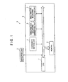
- Embodiment Fig. 1 shows an example of a two-dimensional lattice calibrating method according to an embodiment of the invention.
- a two-dimensional lattice calibrating device 1 includes: a measuring unit that measures positions of marks 1a on an artifact 9 (see Fig. 2 ) for each of a plurality of measurement dispositions n in which at least of a part of the marks 1a is superposed; and an analyzing unit (computer) 3.
- the analyzing unit 3 includes a coordinate setting unit 4 in which coordinate relational equations representing a relationship between a measurement coordinate system of the measuring unit 2 and an artifact coordinate system that identifies the position of the marks 1 a of the artifact 9 for each of the measurement dispositions n are set in advance.
- the coordinate relational equations are, for instance, the below-mentioned equations 1.5b to 1.5e in the present embodiment.
- the coordinate relational equation includes: an origin error An (deviation of the origin) and a setting rotation error ⁇ n as the setting errors that are different per each of the measurements under the respective measurement dispositions n; and a squareness error ⁇ of the artifact coordinate system and deviations ⁇ , ⁇ from a designed value (nominal value) Ni as errors that are common to each of the measurements.
- the analyzing unit (computer) 3 includes: a simultaneous-equations generating unit 5 for generating simultaneous equations for obtaining a deviation Di from the nominal value Ni of an actual position Li of the marks 1a with the use of the coordinate relational equation and a least-squares conditional equations that adjusts least-squares lines that minimize the deviation Di [ ⁇ i ⁇ i] between the actual position Li corresponding to a measurement value mni of the marks 1a and the predetermined nominal value Ni as the axes ⁇ , ⁇ of the artifact coordinate system; and a simultaneous-equations calculating unit 6 that solves the generated simultaneous equations.
- a simultaneous-equations generating unit 5 for generating simultaneous equations for obtaining a deviation Di from the nominal value Ni of an actual position Li of the marks 1a with the use of the coordinate relational equation and a least-squares conditional equations that adjusts least-squares lines that minimize the deviation Di [ ⁇ i ⁇ i] between the actual position Li corresponding to a measurement value mni of
- the least-squares conditional equations are, for instance, equations 1.2a to 1.3b in the present embodiment, which are conditional equations that minimize averages of values adding (or multiplying) the nominal value Ni and the deviation Di and are conditional equations that minimize the averages of the deviations ⁇ i, ⁇ i.
- the simultaneous-equations calculating unit 6 may correct the designed value based on the squareness error ⁇ of the artifact coordinate system calculated by the calculating unit and the deviations ⁇ i, ⁇ i to repeatedly calculate the least-squares lines.
- Each of the L, G, D, N, B and m represents a vector. Incidentally, additional signs (such as an arrow) are omitted in the description.
- Fig. 2 shows an exemplary arrangement of the measuring unit 2.
- the measuring unit 2 includes an imaging device 2A that images the marks 1 a of the artifact 9 to output an image data.
- the artifact 9 is disposed so that an imaging surface (measurement surface) of the imaging device 2A becomes parallel to the surface including the marks 1a.
- a stage 2B may include a mechanism that rotates or translates the artifact 9 at the centroid position thereof in response to a command from the outside.
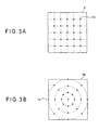
- Figs. 3A and 3B are illustrations showing examples of the artifact.
- Fig. 3A shows a generally available grid plate or a ball plate, in which the marks 1a is arrayed in a square lattice 9. In the example shown in Fig. 3A and the like, the marks 1a are arranged in 5*5 square grid, however, such arrangement is not limiting.
- the calibrating method according to the present embodiment and example tolerates calibration irrespective of the number of the marks.
- Fig. 3B shows the artifact 9 having concentric arrangement of the marks for special purposes.
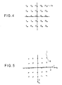
- Fig. 4 shows an example of the numbering of the marks.
- the upper left mark in the figure is designated as the first mark and the lower right mark is designated as twenty-fifth mark.
- At least one of the marks 1a is positioned approximately at the same location as the other mark on the imaging surface after rotating or translating the artifact 9.
- a part of or the entirety of the marks 1a can be superposed (i.e. located approximately at the same position as the previous position of the other mark) by a rotation of ninety degrees or translation in up-down and right-left directions in the figure.
- the marks can be superposed by rotation(s) of forth-five degrees. The measurement disposition allows, though dependent on a rank of the simultaneous equations, superposition of a part of or the entirety of the marks 1a.
- the artifact 9 when the artifact 9 is a square lattice and is rotated anticlockwise by ninety degrees in the figure around the neighborhood of the 13th mark 1a (centroid position), 21st mark 1a is located at a position where the 1st mark 1a was located. Accordingly, mutually independent two measurement values can be obtained for the same mark 1a.
- the artifact 9 is translated downward (in the figure) for one grid, the 1st mark 1a is located at a position where the 2nd mark 1a was located.
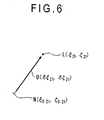
- Fig. 5 shows an exemplary arrangement of the artifact coordinates.
- the artifact coordinates are depicted to be superposed on the nominal coordinates having x0-axis and y0-axis orthogonal to each other.
- the artifact coordinates are represented by least-squares lines that minimize the deviation Di between the actual position Li based on a measurement value m of the marks 1a and the nominal value Ni, of which ⁇ -axis is taken in x0-axis direction and ⁇ -axis is taken in y0-axis direction.
- a difference between the angle formed by the ⁇ -axis and ⁇ -axis and a right angle is the squareness error ⁇ of the artifact coordinates.
- the x0-axis and the ⁇ -axis are superposed and the nominal coordinate axes x0 and y0 are inherently orthogonal, the angle formed by y0-axis and the ⁇ -axis represents the squareness error ⁇ .
- N ⁇ i ⁇ 0 ⁇ i ⁇ 0 ⁇ i
- D ⁇ i ⁇ ⁇ ⁇ i ⁇ ⁇ ⁇ i
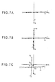
- Figs. 7A to 7C show an example of coordinate axes of the artifact coordinates.
- the least-squares-condition is that an average of the values adding the nominal value ⁇ 0i and the deviation ⁇ i per all of i becomes the minimum (0, in this example) as shown in equation 1.2c.
- ⁇ -axis shown in Fig. 7A can be obtained.
- ⁇ -axis (least-squares line corresponding to x0-axis) can also be obtained by averaging ⁇ i.
- the ⁇ and ⁇ axes are primary average lines taken from the deviations ⁇ i and ⁇ o separated into components in respective directions of the nominal coordinates y0 and x0.
- the "least-squares line" is a primary average line.
- the angular difference between y0-axis and ⁇ -axis is ⁇ 1
- the angular difference between x0-axis and ⁇ -axis is ⁇ 2
- the squareness error between the ⁇ -axis and the ⁇ -axis is ⁇ . Addition of ⁇ 1 and ⁇ 2 amounts to ⁇ .
- ⁇ is positive in a direction for the angle of the two axes to be reduced.
- the intersection of the ⁇ -axis and the ⁇ -axis is set at the same position as the origin of the nominal coordinates for the convenience of description.
- the value from the origin of the nominal coordinates can be obtained by adding Aa to the coordinate value of the artifact coordinate.
- the least-squares conditional equations may be partial differential equations when the least-squares conditional equations are expressed as vectors as shown in equations 1.3a and 1.3b.
- the inclination (tan ⁇ 1) and the intersection ( ⁇ x0) may be calculated so that the square of the deviation ⁇ becomes 0 with respect to variation in the inclination (tan ⁇ 1) of ⁇ -axis relative to y0-axis (tan ⁇ 1) and the variation in the intersection ( ⁇ x0) with the x0-axis.
- the partial differential equation can be solved with normal equation by matrix operation.
- ⁇ is represented with the x0-axis horizontally situated.
- the least-squares lines (coordinate axes of the artifact coordinates) are calculated using the deviations of all of the 5*5 marks in the example shown in Figs. 7A and 7B , the 3rd, 8th, 13th, 18th and 23rd ⁇ may be used for ⁇ -axis and 11th to 15th values may be used for ⁇ -axis.
- the least-squares line is used for the axes of the artifact coordinates mainly in order to minimize as possible the deviations ⁇ i and ⁇ i on ⁇ and ⁇ axes, separate the deviations D from the errors dependent on measurements (origin error A and setting error ⁇ ) and rotation error B of the entire artifact and avoid generation of digit number difference of the measurement value mni per respective i. Accordingly, an approximate expression may alternatively be employed instead of the least-squares line itself.
- the "least-squares line” encompasses the formula such as the equations 1.2c and 1.2d and more simplified approximate expressions.
- equations 1.2a and 1.2b as the basis for applying the least-square method are interpreted as a part of the "least-squares conditional equations".
- the least-squares line can be uniquely specified on the nominal coordinates by parameters of ⁇ 1 (inclination) shown in Fig. 7A and ⁇ x0 (intersection with x0-axis) shown in Fig. 7C with regard to ⁇ axis.
- the ⁇ -axis can also be specified by ⁇ 2 and ⁇ y0.
- the least-squares line is initially acquired in an approach that solves a normal equation, and, after the measurement value is corrected and the like, the simultaneous equations may be solved.
- the numeric calculation can be done without using a normal equation.
- the deviation D and ⁇ can be simultaneously and collectively obtained.
- the nominal value may be corrected by the calculated ⁇ and the deviation D as a new nominal value and the least-squares line and the like may be calculated, thereby further improving the calculation accuracy.
- Figs. 8A, 8B , 9A and 9B show an example of measurement disposition n.
- measurement coordinates having x and y axes and square error ⁇ of the measurement coordinates will be described below in the example.
- ⁇ n the component included in the angle formed by x0-axis of the nominal coordinates and ⁇ -axis that is caused when the artifact 9 is mounted is represented as ⁇ n.
- the y0 and x0 axes of the nominal coordinates are represented with normal arrows.
- the ⁇ and ⁇ axes of the artifact coordinates are represented with an arrow having one triangle tip end.
- the measurement coordinates are represented with two arrows having two triangles at the tip end thereof.
- the axis name in parentheses represents a reference parallel straight line.
- the dotted line is a linear line orthogonal to the ⁇ -axis.
- the measuring unit 2 conducts the 1st measurement after aligning the respective coordinate axes and point-sequence directions of the marks (1st measurement disposition).
- the point-sequence direction is the direction of the coordinate axes x0, y0 of the nominal coordinates.
- the x0-axis is aligned with ⁇ -axis and y0-axis is aligned with ⁇ -axis.
- the setting rotation error of the measurement disposition is ⁇ 1.
- the sign ⁇ represents a squareness error of the angle formed by the least-squares lines ⁇ and ⁇ shown in Figs. 7A to 7C , which is independent of ⁇ n.
- X1 and Y1 represents a deviation between the origin of the nominal coordinates and the origin of the artifact coordinates in the present embodiment.
- the origin error includes disposition error As at the 1st measurement disposition and deviation Aa between the intersection of the least-squares lines (i.e. the origin of the artifact coordinates) and the origin of the nominal coordinates.
- Xn, Yn and ⁇ n are determined depending on the measurement dispositions n.
- ⁇ is not dependent on the measurement disposition but is a constant.
- the measuring unit 2 rotates in-plane the 1st measurement disposition by 90 degrees around the centroid position thereof (2nd measurement disposition) to conduct the second measurement.
- the "in-plane” rotation means that the artifact 9 is rotated while keeping the plane including the marks on the surface of the artifact 9 parallel to the imaging surface of the measuring unit 2.
- the artifact 9 is rotated by 90 degrees anticlockwise.
- the 1st mark 1a is moved to the position of the 5th mark shown in Fig. 8A .
- the angle formed by x0-axis and ⁇ -axis is ⁇ /2+ ⁇ 2.
- the measuring unit 2 rotates in-plane the 1st measurement disposition by 180 degrees around the centroid position thereof (3rd measurement disposition) to conduct the third measurement.
- the even-number component of the deviation Di can be separately acquired.
- the angle formed by x0-axis and ⁇ -axis is ⁇ + ⁇ 3.
- the measuring unit 2 translates the 1st measurement disposition by an interval ⁇ of the marks (4th measurement disposition) to conduct the fourth measurement.
- a rotation error may be generated before and after the translational movement in mounting the artifact.
- ⁇ 1 and ⁇ 4 are variables determined separately.
- the measurement disposition is translated per one mark in downward direction in the figure. Accordingly, the 1st mark 1a is moved to the position of the 2nd mark 1a shown in Fig. 9A .
- the row including the 5th mark 1a is laid outside the measurement range during the 1st to 3rd measurement dispositions.
- the measurement values for one row or column is decreased by the one-mark translational movement. It should be understood that all of the marks may be measured by widening the measurement range.
- At least three measurement values for the same mark are obtained by four measurement processes by the rotations and translational movement.
- the artifact coordinates are rotated in accordance with the rotations.
- G i A n + N i + B ni + D i
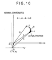
- Fig. 10 shows a relationship between the parameters of the coordinate relational equation in the 1 st measurement disposition, in which An represents an origin error, Bn represents a rotation error, Ni represents a nominal value, Di represents a deviation from the nominal value to the actual position Li and Gi represents an actual value subtracting the measurement error e from the measurement value mni, as expressed in equation 1.4a.
- the measurement error e is known.
- a correction equation or a correction value for removing the measurement error from the measurement value is known (incidentally, an exemplary process for simultaneously correcting the measurement error e will be described below in the Example).
- the origin error An includes an origin error Aa (and Am in the Example) between the coordinates and a setting origin error Asn which is a difference between the centers of the measurement dispositions caused during the setting process.
- the rotation error Bn is an error depending on the setting angle error ⁇ n caused when setting each of the measurement dispositions n and ⁇ in accordance with the inclination of the least-squares line, which is acquired for each of the measurement dispositions n.
- the angular errors ⁇ n, ⁇ n in the equation 1.4d can be defined in advance in accordance with the coordinate relationship of the measurement disposition.
- the ⁇ and ⁇ (mentioned below) can be defined as a squareness error, which can be treated as a rotation error when they are sufficiently small.
- the ⁇ 1 in the 1st measurement disposition is equal to - ⁇ 1 + ⁇ and ⁇ 1 is equal to ⁇ 1.
- Equations 1.5c to 1.5e are respectively related to the 2nd to 4th measurement dispositions.
- the coordinate relational equations are the equations 1.5b to 1.5e in the present embodiment.
- the setting error influences on the origin error An and the rotation error Bn.
- the rotation error Bn is an error caused by the rotation error components ⁇ , ⁇ , which are obtained by adding/subtracting the squareness error ⁇ and the setting rotation error ⁇ n in accordance with coordinates relationship in the respective measurement dispositions.
- the simultaneous-equations generating unit 5 uses the equation 1.5 to subtract the measurement error e and the nominal value Ni from the measurement value mni at the 1st measurement disposition, which is substituted into the left-side of the equation 1.5b. Further, the nominal value Ni is substituted into Bn on the second item on the right side. Accordingly, the same number of linear expressions as the number of the marks 1a are acquired. Similarly, the simultaneous equations are established for the 2nd to 4th measurement dispositions. Subsequently, the simultaneous-equations generating unit 5 reads out the least-squares conditional equations 1.2.
- the simultaneous-expressions generating unit 5 may additionally read out a conditional equation that equalizes the distances ⁇ between the respective marks in accordance with the need for rank adjustment and accuracy improvement.
- the simultaneous-equations calculating unit 6 solves the simultaneous equations that are generated by the simultaneous-equations generating unit 5.
- the parameters for identifying the least-squares line ⁇ and ⁇ as the axis of the artifact coordinates may be initially calculated, or, alternatively, all components including the identification of the least-squares line may be collectively obtained by arithmetic calculation by QR-decomposition and the like without solving normal equations.
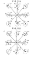
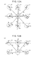
- Figs. 11A, 11B , 12A and 12B show a relationship between the deviation Di around the centroid position and the measurement error ej.
- j represents the position on the side of the measuring unit (the number of the measurement range in the Example).
- Fig. 11A shows the 1st measurement disposition, where the number ofj coincides with the number of i.
- the measurement direction can be rotated by 90 degrees for measurement.
- the relationship between i and j can be reflected on the measurement values m per each measurement disposition with independent combinations by the measurement accompanying rotation and translation without fixing the relationship between i and j.
- the origin error Asn and the setting rotation error ⁇ n are equal at the respective measurement dispositions n.
- the origin error Asn and the setting rotation error ⁇ n influence on the measurement values of all the marks measured at a specific (n-th) measurement disposition.
- the errors for each of the measurement dispositions can be acquired based on the value of the deviation D.
- the deviation D can be acquired from the errors for each of respective measurement dispositions n.
- the setting errors that are actually different for each of the measurement dispositions are Asn for the origin error A and ⁇ n for the rotation error B.
- the coordinate relational equations can be defined with the squareness error ⁇ and the origin error Aa between the coordinates being constant irrespective of the setting errors between the respective measurement dispositions, thereby separating the setting errors Asn and ⁇ n from the other errors.
- the measurement value m is obtained while, preferably, rotating the artifact 9 by 180 degrees.
- correction value (deviation) D considering the influence of not only odd-number component error but also the even-number component error can be obtained for each of the marks.
- the simultaneous equations can be defined while separating the coordinate relational equation and the setting error.
- the simultaneous equations can be derived using the measurement value mni, measurement error ei and the nominal value Ni, which are subject to calculation. Accordingly, the setting error component can be efficiently removed. Since the coordinate value of the actual position Gi is determined using the least-squares line, the difference between the deviations of each of the marks can be reduced, so that stable arithmetic calculation can be made without deteriorating accuracy by digit cancellation and the like.
- the influence of the even-number components of the errors can be efficiently eliminated and the origin error, rotation error, measurement error and the deviation can be efficiently separated.
- arithmetic calculation can be conducted at the proximity of the marks while minimizing the effect of the setting error during the measurement. Further, the systematic error Di of the marks of the artifact can be acquired separately from the origin error An and the rotation error Bn including the setting error of the artifact.
- Measurement number n the number of the measurement disposition (each of the measurements)
- Mark number i the number of each of the marks of the artifact (e.g. a square lattice).
- Measurement range number j the number of each of the measurement ranges (e.g. a measurement grid) of the measuring unit
- Nominal coordinates coordinates for defining the artifact coordinates and the measurement coordinates, which have two axes of x0-axis and y0-axis that pass an origin and are orthogonal with each other.
- the artifact coordinates with the origin error and the squareness error ⁇ being corrected coincide with the nominal coordinates.
- the measurement coordinates with the origin error and the squareness error ⁇ being corrected coincide with the nominal coordinates.
- Nominal coordinate axes two axes (x0-axis and y0-axis) that pass the origin and are orthogonal with each other.
- Nominal coordinates origin Intersection of x0-axis and y0-axis.
- Nominal value Ni coordinate value [ ⁇ 0i ⁇ 0i] at each of the marks in the nominal coordinates.
- Nominal corrected coordinate value When the artifact has a correction value C, the coordinate value of the position of the respective marks after being corrected by the correction value.
- the correction value is, for instance, the deviation D in the previous calibration.
- Artifact coordinates Coordinates with least-squares lines that minimize the difference (deviation) between the nominal value Ni and the actual position Li of the respective marks in the x0 and y0 directions.
- Artifact coordinate axes ⁇ -axis corresponding to x0-axis and ⁇ -axis corresponding to y0-axis.
- ⁇ -axis and ⁇ -axis The least-squares lines (primary average lines) that minimize the position error (excluding the measurement error) of the respective marks represented by the nominal coordinates.
- Artifact coordinates origin Centroid position of the point sequence of the respective marks, which is the intersection of ⁇ -axis and ⁇ -axis.
- Squareness error ⁇ Difference between an angle formed by ⁇ -axis and ⁇ -axis and a right angle, in which positive direction is taken in a direction for the angle to be reduced.
- Actual position Li Actual coordinate values [ ⁇ i ⁇ i] of the respective marks in the artifact coordinates.
- the deviation may include a scale error ⁇ a of the artifact.
- Measurement coordinates Coordinates of the respective measurement ranges including the measurement value mni of the respective marks and the measurement error ej (may include scale error ⁇ b in this Example) having axes of the least-squares lines that minimize the respective measurement errors in x direction and y direction.
- Measurement coordinate axes x-axis corresponding to x0-axis and y-axis corresponding to y0-axis.
- x-axis and y-axis The least-squares lines (primary average lines in the respective directions) that minimize the measurement error e (excluding the scale error ⁇ b) of the measurement value mni represented by the nominal coordinates.
- Measurement coordinates origin Centroid position of the point sequence of the measurement range, which is the intersection of the x-axis and the y-axis.
- Measurement range j-numbered range(s) on the measurement coordinates containing the measurement value m of the respective marks, measuring unit error e of the measurement value (and nominal value N).
- Squareness error ⁇ Difference between an angle formed by x-axis and y-axis and a right angle, in which positive direction is taken in a direction for the angle to be reduced.
- Setting rotation error ⁇ n An angle formed by the x-axis of the measurement coordinates and ⁇ -axis of the artifact coordinates.
- Origin error 1st item of the right side of the coordinate relational equation of the respective measurement numbers n.
- Aa Deviation from the artifact coordinates to the origin of the nominal coordinates, which is the deviation of the centroid position of the marks of the artifact (origin of square lattice coordinates).
- the measurement value can be treated as the value on the nominal coordinates except for the rotation error.
- Bn A value multiplying ( ⁇ + ⁇ + ⁇ n) by the nominal value Ni, which is the rotation error of the respective marks obtained by summation of the angle errors.
- Ci [ ⁇ ci, ⁇ ci]: Correction value of the respective marks of the artifact (known).
- Ni [ ⁇ 0i, ⁇ 0i]: Nominal value of the respective marks (known).
- Di [ ⁇ i, ⁇ i]: Deviation between the actual positions and the respective nominal values.
- Li [ ⁇ i, ⁇ i]: Actual lattice position of the respective marks.
- Gi [xi, yi]: Actual position of the respective marks in the measurement coordinate system, where the influence of the measurement error is removed.
- mni [mnxi, mnyi]: Measurement value of the respective marks in the measurement coordinates.
- ej [exi(xi, yi), eyi(xi, yi)]: Error of the measurement value by the measuring unit.
- the two-dimensional lattice calibrating device 1 includes: a measuring unit 20 that measures the positions of the marks 1a for each of the measurement dispositions in accordance with a plurality of measurement dispositions in which at least a part of the marks 1a of the artifact 9 is superposed; a storage 30 that stores the measurement value mni for each of the measurement dispositions, predetermined formulae and the nominal value Ni of the respective marks 1a; and a computing unit 40 that calculates the deviation D from the nominal value Ni to the actual value using the measurement value mni and the nominal value Ni stored in the storage 30 according to the predetermined formulae.
- the storage 30 includes: a measurement value storage 31 that stores the measurement value m for each of the measurement dispositions within the measurement coordinates in which the difference between the angle formed by the least-squares lines that minimize the measurement error ej of the measuring unit 20 and a right angle; and a nominal value storage 32 that stores the nominal value Ni of the respective marks within the nominal coordinates.
- the nominal value Ni (or a value added with/subtracted by the correction value C, when the correction value C has been obtained) is known.
- the measurement value mni becomes known after completion of the measurement at the respective measurement dispositions.
- the measurement value mni to be stored may be set as a value corrected by the squareness error ⁇ or, alternatively, may be set as the value detected by the measuring unit 2.
- the storage 30 further includes a coordinate relational equation storage 33 that stores the coordinate relational equations for each of the measurement dispositions n.
- the coordinate relational equations are derived in advance assuming that the actual value L of the respective marks of the artifact coordinates and the actual value G of the respective marks within the measurement coordinates are equal.
- the artifact coordinates are coordinates in which the difference between the angle formed by the least-squares lines ( ⁇ and ⁇ axes) that minimize the deviation D between the nominal value Ni and the actual position Li of the artifact 9 and the right angle is the squareness error ⁇ .
- the coordinate relational expressions are relational expressions showing the relationship among the origin error An (deviation of the origin of the respective coordinates (the artifact coordinates and the measurement coordinates) from the nominal coordinates origin), the rotation error Bn based on the squareness errors ⁇ , ⁇ and the setting rotation error ⁇ n, the nominal value Ni, the measurement error ej and the measurement value mni.
- the coordinate relational equations are equations that provides a relationship among An, Bn, Ni, mni and ej per each of the measurement dispositions.
- the storage 30 further includes: a least-squares conditional equation storage 34 that stores a least-squares conditional equation for setting the respective axes of the respective coordinates as the least-squares lines; and a rank-adjusting equation storage 35 that stores a rank-adjusting equation for adding the least-squares conditional equation according to the number of the unknowns.
- the equations stored in advance in the storage 30 are the coordinate relational equation, the least-squares conditional equation and the rank-adjusting equation as necessary.
- the computing unit 40 includes a simultaneous-equations generating unit 41 and a simultaneous-equations calculating unit 6 for solving the simultaneous equations generated by the simultaneous-equations generating unit 41.
- the simultaneous-equations generating unit 41 reads out the measurement value mni of the respective marks per each of the measurement dispositions n and the nominal value Ni to assign into the coordinate relational equations per each of the measurement dispositions stored in the coordinate relational equation storage 33. Further, the simultaneous-equations generating unit 41 reads out the least-squares conditional equations to generate simultaneous equations for acquiring the deviation Di from the nominal value Ni to the actual position Li of the respective marks using the measurement value mni.
- the two-dimensional lattice calibrating device can achieve the same functions and effects of the above embodiment.
- the two-dimensional lattice calibrating device can separately acquire the measurement error ej, whereby preliminary calibration of a measuring instrument becomes unnecessary and the deviation and the measurement error of the measurement value can be integrally and separately measured.
- Fig. 14 is an illustration showing an example of the measurement coordinates.
- the coordinate system is defined also on the measuring unit 2.
- the measurement error ej is considered only on the respective measurement areas 1b of the measurement coordinates and the origin, x-axis and y-axis are defined in the same manner as the artifact coordinates, where the squareness error between the both axes are represented by ⁇ .
- the x-axis and the y-axis are respectively the least-squares lines (primary average linear lines) that minimize the value of the measurement error ej.
- the scale error ⁇ b is not included in the measurement error ej.
- the scale error ⁇ may be separately calculated after measuring ej: or the scale error may be calibrated in advance to correct the measurement value; or ej may be multiplied by the scale error ⁇ b in the equation 1.7 to calibrate simultaneously with calibration of ej.
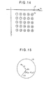
- Fig. 15 shows an example of the measurement area 1b.
- the measurement value mni (or the measurement value after correcting with the scale error) contains error ej on the side of the measuring unit 2. Addition of ej to the measurement value mni amounts to the actual value L obtained by adding the deviation Di to the nominal value Ni after removing the influence of the origin error An and the rotation error Bn.
- the positions of the respective grids are not superposed in a strict sense on account of the setting errors and errors of the marks. However, it is sufficient for calibration that the positions of the marks are located within a range in which the errors of the measuring unit can be regarded as being hardly changed.
- Fig. 16 shows a relationship among the nominal coordinates, the measurement coordinates and the artifact coordinates.
- the origins of the measurement coordinates and the nominal coordinates are identical for the sake of facilitating the explanation. Further, it is assumed that there is no angular error between the x0-axis of the nominal coordinates and the x-axis of the artifact coordinates.
- mni An (1st item on the right side) + Bn (2nd item on the right side) + Di (3rd item on the right side) + ej (4th item on the right side)
- the coordinate relational equation storage 33 stores the equations 1.7b to 1.7e.
- the measuring unit 2 identifies the respective measurement values using the measurement number n and the mark number i.
- the simultaneous-equations generating unit 41 assigns the measurement values per each measurement number into the left side in accordance with the mark number and also assigns the nominal value into the left side and the second item on the right side, thereby generating simultaneous equations for the respective marks for each of respective measurement numbers.
- the coordinate relational equation storage 33 stores the coordinate relational equation approximating the rotation error B with a primary equation.
- the simultaneous-equations generating unit 41 conducts addition and subtraction of the squareness errors ⁇ , ⁇ of the respective coordinates and the setting angular error ⁇ n for each of the measurement dispositions and reads out the equations for acquiring the rotation error Bn by the multiplication with the nominal value Ni per each of the marks 1a from the coordinate relational equation storage 33 to assign the corresponding nominal values Ni to each of the equations for the measurement values mni.
- the simultaneous-equations calculating unit 6 solves the simultaneous equations as primary equations.
- the simultaneous-equations calculating unit 6 may collectively conduct arithmetic calculation for the simultaneous equations by the coordinate relational equations, the least-squares conditional equations and necessary rank-adjusting equations without solving normal equations.
- the artifact is rotated by 90 degrees around the z-axis to measure the position of the respective marks.
- i j 1 1 ⁇ 2 2 ⁇ [ 24 24 ] [ 25 25 ]
- ei takes the coordinate value of the measuring instrument as a parameter, ei can be represented as in the equation 2.2 using a parameter j (grid number of the measuring instrument).
- the measurement value of the 1st measurement can be represented by the equation 2.3.
- equation 2.5a When the equation 2.5 is substituted by the equation 2.1, equation 2.5a can be obtained.
- the equation 2.5b can be obtained by expanding the equation 2.5a, which can be approximated as the equation 2.5c by omitting the multiplication of apparently minute values ⁇ i and ⁇ i.
- the measurement value is given by the equation 2.3, which is set as the equation 2.6a and is assigned with the equation 2.5c to be modified as the equation 2.6b.
- the artifact In the 2nd measurement disposition, without changing (shifting) the setting position, the artifact is rotated by 90 degrees about the z-axis around the origin relative to the 1st measurement disposition to measure the position of the respective marks.
- an equation 2.7b can be derived from the equation 2.7a as in the 1st measurement.
- the artifact is rotated by 180 degrees about the z-axis around the origin relative to the 1st measurement disposition to measure the position of the respective marks.
- conditional equations for setting the respective axes of the respective coordinates as least-squares lines are introduced.
- the coordinate relational equations contain the measurement error e, the squareness error ⁇ of the measurement coordinate system and the scale error ⁇ b of the measurement coordinate system as errors common to all of the measurements.
- the least-squares conditional equations include a conditional equation that minimizes the average of the deviations ⁇ , ⁇ and the average of the measurement error e corrected by the scale error ⁇ b of the measurement coordinate system.
- the simultaneous-equations calculating unit 6 preferably calibrate the deviations ⁇ , ⁇ simultaneously with calibrating the scale error ⁇ b of the measuring unit and the squareness error ⁇ of the measurement coordinate system.
- the scale error ⁇ a of the artifact can be separated from the deviation D.
- conditional equations may be used as long as the rank of the simultaneous equations is not degraded. For example, several points may be picked up and a condition for fixing the coordinate axis or a conditional equation for correcting the scale error may be added solely for the points.
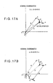
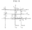
- Point p2 on the ⁇ -axis is an intersection of the ⁇ -axis and a line passing the point p1 and orthogonal to the ⁇ axis.
- Length r1 from the origin of the artifact at which the ⁇ axis and the ⁇ -axis orthogonally crosses to the point p2 is given by an equation 5.1b.
- length r2 from the point p1 to the point p2 is given by an equation 5.1c.
- the point p3 is the intersection of a linear line passing the point p1 and parallel to the x-axis of the measurement coordinates and y0-axis of the nominal coordinates.
- the coordinate value on y0-axis of the nominal coordinates is given by an expression 5.2a.
- an equation 5.2c can be obtained by assigning the equations 5.1b and 5.1c into the equation 5.2b, which is approximated as an equation 5.2d.
- the point p4 is the intersection of a linear line passing the points p1 and p3 and the y-axis of the measurement coordinates.
- the point p4 is yi as a component of Gi.
- the point p4 can be represented as in an equation 5.3a using the squareness error ⁇ of the nominal coordinates and the measurement coordinates.
- the second item and the third item of the equation 5.3b can be represented by multiplication of matrixes.
- Point p5 is the intersection of a linear line passing the point p1 and parallel to the ⁇ -axis and the x-axis of the measurement coordinates.
- the length from the point p5 to X1 can be expressed as an equation 5.4a.
- r6 and r7 can be represented by an equation 5.4b, into which the equations 5.1b and 5.1c are assigned to obtain an equation 5.4c.
- the equation is approximated as an equation 5.4d, which is further modified as an equation 5.4e.
- Point p6 is the intersection of a linear line passing the point p1 and parallel to the y-axis of the measurement coordinates and the x-axis.
- the x coordinate value of the point p6 is xi (a component of G), which is represented by an equation 5.5a.
- r8 is equal to the length from the point p3 to the point p4, which is represented by an equation 5.5b and r5 can be represented by the equation 5.4e, which are assigned to obtain an equation 5.5c.
- the equation 5.6 is equal to the above described equation 2.4.
- the artifact is rotated anticlockwise by 90 degrees.
- the coordinate value is derived with the use of the value of ⁇ i, the value of ⁇ i, ⁇ , ⁇ and ⁇ .
- r1 and r2 are defined according to the equations 5.1b and 5.1c.
- the equation 5.2d is derived from the equation 5.2a representing the point p3, which is expanded to the point p4 by the equations 5.2a and 5.3b.
- the equation 5.2b is expressed in a matrix shown in the equation 5.6.
- the equation 5.4e is derived from the equation 5.4a representing the point p5, which is expanded to the point p6 by the equations 5.5a to 5.5f.
- the equation 5.5f is expressed in a matrix shown in the equation 5.6.
- the rotation error can be calculated in the same manner as the 1st measurement disposition.
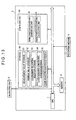
- the artifact is measured by the measuring unit 2 shown in Figs. 1 and 13 .
- the coordinates are set by the coordinate setting unit 4 shown in Fig. 1 .
- the coordinate relational equation is set in the storage 30 during the coordinate setting step in the example shown in Fig. 13 .
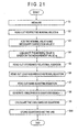
- the simultaneous-equations-generating steps S2 to S8 are information processing by the simultaneous-equations generating unit 5 shown in Fig. 1 .
- the simultaneous equations may be generated by the simultaneous-equations generating unit 41 of the computing unit 40.
- the simultaneous equations calculating step S9 is information processing for solving the simultaneous equations by the simultaneous-equations calculating unit 6 shown in Figs. 1 and 13 .
- the simultaneous-equations generating unit 41 reads out the nominal value Ni of the marks 1a from the nominal value storage 32 in accordance with the lens of the measuring unit 2, the identification number of the artifact and the like.
- the simultaneous-equations generating unit 41 adds the correction value Ci to the nominal value Ni or subtracts the correction value Ci from the nominal value Ni.
- the correction value Ci is, for instance, the deviation Di measured during previous calibration of the two-dimensional lattice.
- the nominal value Ni is the designed position at first. However, once obtaining the deviation Di of the marks, the value adding the deviation Di as the correction value Ci to the nominal value Ni may be used as a new nominal value Ni, which is used for further estimation. In this case, the values of Xn, Yn and ⁇ are reduced and the accuracy of the arithmetic calculation can be improved.
- the simultaneous-equations generating unit 41 subtracts the nominal value from the measurement value m (step S4).
- the subtraction is independently conducted for x and y.
- the coordinate relational equations from 1.7a to 1.7e and the like are read out from the coordinate relational equation storage 33 (step S5).
- the simultaneous-equations generating unit 41 further reads out the least-squares conditional equations from the equations 3.1a to 3.2b (step S6) and further reads out the rank-adjusting equations from the equations 4.1a to 4.2b (step S7).
- the simultaneous-equations generating unit 41 assigns the nominal value Ni and the value subtracting the nominal value Ni from the measurement value mni into the formulae that are read out (step S8).
- the value subtracting the measurement value from the nominal value Ni is assigned to the left side of the coordinate relational equations 1.7a to 1.7e. The value is assigned per each of the measurement numbers (n) and per each of the mark numbers (i).
- the nominal value Ni is substituted into the second item on the right side of the coordinate relational equation.
- the nominal value Ni is assigned to the least-squares conditional equations and the rank-adjusting equations. The assignment of the nominal value and the like is conducted using the mark number i.
- the simultaneous equation calculating unit 6 calculates the simultaneous equations generated in the step S8. For instance, the simultaneous equation calculating unit 6 obtains a Jacobian matrix from the simultaneous equations, which is subject to arithmetic calculation after QR-decomposition. Accordingly, all of A (first item on the right side of the equation 1.7), ⁇ , ⁇ and ⁇ n in B (second item), D (third item) and e (fourth item) can be collectively and simultaneously obtained. Thus, all of the parameters can be obtained after being optimized by the least-squares conditional equations.
- the computing unit 40 stores the parameters (the value of An, Bn, Di and ej) of the coordinate relational equations in the storage 30 together with the number for distinguishing the mark of the artifact from the other artifact, objective lens and the like.
- the information processing in the steps S2 to S10 shown in Fig. 21 may be achieved by executing a two-dimensional lattice calibrating program with the analyzing unit 3 (computer).
- the two-dimensional lattice calibrating program includes a measuring unit 2 and a computer (analyzing unit) 3 connected with the measuring unit 2 to compute the deviation Di of the mark using the measurement value mni per each of the measurement dispositions n.
- the two-dimensional lattice calibrating program operates for the computer 3 to work as the storage 30 that stores the measurement value mni per each of the measurement dispositions, predetermined arithmetic formulae and the nominal value Ni of the marks and the computing unit 40 that calculates the deviation Di between the nominal value Ni and the actual value Li using the measurement value mni and the nominal value Ni stored in the storage 30 according to the predetermined arithmetic formula.
- the program further operates the storage 30 as the measurement value storage 31, the nominal value storage 32, the coordinate relational equation storage 33, the least-squares conditional equation storage 34 and the rank-adjusting equation storage 35.
- the program is, for instance, connected with the measuring unit 2 to control the measurement value inputted from the measuring unit 2 in the measurement value storage 31. Further, the program urges a user of the computer to input the coordinate relational equations, the least-squares conditional expression and the rank-adjusting equation to store the equations.
- the program further operates the computing unit 40 as the simultaneous-equations generating unit 41 and the simultaneous equation calculating unit 6.
- the program operates the computer 3 to do the processing from the step S2 to the step S8 to make the computer 3 function as the simultaneous-equations generating unit 41.
- corresponding nominal value Ni is specified using the number for identifying the artifact 9, the objective lens of the measuring unit 2 and the like.
- the processing for subtracting the nominal value Ni from the measurement value mni in the step S4 the number is subtracted per each of the number of the mark (i).
- the coordinate relational equation and the least-squares conditional expression in the steps S5 and S6 are selected in accordance with the type and the number of the measurement disposition, which also applies to the rank-adjusting equation.
- the program operates the computer to calculate the simultaneous equations.
- the program may control the computer to rely on a generally available matrix-calculating software for calculating the simultaneous equations.
- the two-dimensional lattice calibrating program may be constituted so that the program itself conducts a calculation or, alternatively, contain a process or command for operating the other program.
- the two-dimensional lattice calibrating program may be stored in a recording medium 9 to be installed in the two-dimensional lattice calibrating device.
- the two-dimensional lattice calibrating device is not limited to that described in the above embodiment, but may be modified in a variety of manners as long as an object of the present invention can be achieved.
- the optimum solution may alternatively be calculated by least-squares method by increasing the number of measurements.
- the calibration accuracy can be further improved by increasing data redundancy.
- the deviation and measurement error may be expressed using a spline function and the like. In this case, the value of the error is not directly estimated but the parameter of the function will be estimated.
- the two-dimensional lattice calibrating device allows highly accurate measurement of the position of marks without inverting an artifact.
Landscapes
- Physics & Mathematics (AREA)
- General Physics & Mathematics (AREA)
- Length Measuring Devices By Optical Means (AREA)
- A Measuring Device Byusing Mechanical Method (AREA)
- Length Measuring Devices With Unspecified Measuring Means (AREA)
- Complex Calculations (AREA)
- Apparatus For Radiation Diagnosis (AREA)
Applications Claiming Priority (1)
| Application Number | Priority Date | Filing Date | Title |
|---|---|---|---|
| JP2007137153A JP5468726B2 (ja) | 2007-05-23 | 2007-05-23 | 二次元格子校正装置、二次元格子校正プログラム、記録媒体 |
Publications (2)
| Publication Number | Publication Date |
|---|---|
| EP1995554A2 true EP1995554A2 (fr) | 2008-11-26 |
| EP1995554A3 EP1995554A3 (fr) | 2009-11-18 |
Family
ID=39706294
Family Applications (1)
| Application Number | Title | Priority Date | Filing Date |
|---|---|---|---|
| EP08156718A Withdrawn EP1995554A3 (fr) | 2007-05-23 | 2008-05-22 | Dispositif d'étalonnage de réseau bidimensionnel, son procédé, programme et support d'enregistrement |
Country Status (3)
| Country | Link |
|---|---|
| US (1) | US7765079B2 (fr) |
| EP (1) | EP1995554A3 (fr) |
| JP (1) | JP5468726B2 (fr) |
Families Citing this family (10)
| Publication number | Priority date | Publication date | Assignee | Title |
|---|---|---|---|---|
| EP2100189B1 (fr) * | 2006-11-09 | 2018-06-20 | Carl Zeiss SMT GmbH | Procédé de détermination d'erreurs résiduelles |
| JP5438988B2 (ja) * | 2009-02-17 | 2014-03-12 | 株式会社ミツトヨ | 測定システムおよび干渉計 |
| DE102009003503A1 (de) * | 2009-02-18 | 2010-08-19 | Vistec Semiconductor Systems Gmbh | Verfahren zur Kalibrierung eines Messtisches einer Koordinaten-Messmaschine |
| JP5325048B2 (ja) * | 2009-08-25 | 2013-10-23 | 株式会社ミツトヨ | 誤差伝播による出力データの精度評価方法 |
| JP2012007942A (ja) * | 2010-06-23 | 2012-01-12 | Fuji Xerox Co Ltd | 位置測定装置 |
| US10845192B2 (en) * | 2017-09-13 | 2020-11-24 | Shawn Thomas Lause | Machine tool test fixture |
| TWI677413B (zh) | 2018-11-20 | 2019-11-21 | 財團法人工業技術研究院 | 用於機械手臂系統之校正方法及裝置 |
| CN113804148B (zh) * | 2021-08-04 | 2024-04-19 | 吉林建筑科技学院 | 一种基于动态基准的测量平差方法 |
| CN113701798B (zh) * | 2021-08-29 | 2024-01-19 | 孙恺欣 | 一种二维栅格标准板的校准装置和方法 |
| CN114674249B (zh) * | 2022-03-28 | 2023-02-07 | 上海大学 | 一种筒体嵌套装配对中的视觉测量引导装置、方法及系统 |
Family Cites Families (9)
| Publication number | Priority date | Publication date | Assignee | Title |
|---|---|---|---|---|
| US4583298A (en) * | 1984-03-07 | 1986-04-22 | Hewlett-Packard Company | Auto calibration method suitable for use in electron beam lithography |
| US5798947A (en) | 1996-09-25 | 1998-08-25 | The Board Of Trustees Of The Leland Stanford, Jr. University | Methods, apparatus and computer program products for self-calibrating two-dimensional metrology stages |
| DE19734695C1 (de) * | 1997-08-11 | 1998-11-05 | Leica Mikroskopie & Syst | Verfahren zur Korrektur der Messfehler einer Koodinaten-Messmaschine |
| JPH11175762A (ja) * | 1997-12-08 | 1999-07-02 | Katsushi Ikeuchi | 光環境計測装置とそれを利用した仮想画像への陰影付与装置及び方法 |
| JP2004198110A (ja) * | 2002-12-16 | 2004-07-15 | Dainippon Printing Co Ltd | 校正用基板 |
| JP4445717B2 (ja) | 2003-06-10 | 2010-04-07 | 株式会社ミツトヨ | 画像データ処理装置、画像データ補正方法、画像測定機、画像データ処理プログラムおよびこのプログラムを記録した記録媒体 |
| JP4323268B2 (ja) | 2003-09-09 | 2009-09-02 | 株式会社ミツトヨ | 形状測定装置、形状測定方法、形状解析装置 |
| US6948254B2 (en) * | 2003-10-27 | 2005-09-27 | Micronic Laser Systems Ab | Method for calibration of a metrology stage |
| JP2005326247A (ja) * | 2004-05-14 | 2005-11-24 | Nippon Telegr & Teleph Corp <Ntt> | 校正装置及び校正方法並びに校正プログラム |
-
2007
- 2007-05-23 JP JP2007137153A patent/JP5468726B2/ja active Active
-
2008
- 2008-05-21 US US12/153,573 patent/US7765079B2/en active Active
- 2008-05-22 EP EP08156718A patent/EP1995554A3/fr not_active Withdrawn
Non-Patent Citations (1)
| Title |
|---|
| TAKESHI WAGOU; ISAO YONEKURA: "Value-Determining Calibration of a Ball Plate by CMM", JOURNAL OF IWATE INDUSTRIAL RESEARCH INSTITUTE, July 2005 (2005-07-01), Retrieved from the Internet <URL:http:l/www.pref.iwate jphkiri/inforltheme/2004/pdf/H16-27-cmm.pdf> |
Also Published As
| Publication number | Publication date |
|---|---|
| EP1995554A3 (fr) | 2009-11-18 |
| JP2008292259A (ja) | 2008-12-04 |
| US20080294364A1 (en) | 2008-11-27 |
| JP5468726B2 (ja) | 2014-04-09 |
| US7765079B2 (en) | 2010-07-27 |
Similar Documents
| Publication | Publication Date | Title |
|---|---|---|
| EP1995554A2 (fr) | Dispositif d'étalonnage de réseau bidimensionnel, son procédé, programme et support d'enregistrement | |
| US9031805B2 (en) | Geomagnetic field measurement device, offset determination method, and computer readable recording medium therefor | |
| JP5033572B2 (ja) | 位置座標の測量方法 | |
| US7245982B2 (en) | System and process for measuring, compensating and testing numerically controlled machine tool heads and/or tables | |
| US9560335B2 (en) | Device and system for three-dimensional scanning, and method thereof | |
| KR20080026395A (ko) | 자기 환경을 고려한 컴퍼스 센서의 교정 방법 및 장치와이를 이용한 방위각 측정 방법 및 장치 | |
| JP2008261755A (ja) | 情報処理装置、情報処理方法 | |
| WO2012044964A2 (fr) | Appareils et procédés destinés à estimer l'angle de lacet d'un dispositif dans un système de référence gravitationnel en utilisant des mesures de capteurs de mouvement et un magnétomètre attaché au dispositif | |
| EP2841876A1 (fr) | Procédé et appareil améliorés pour effectuer une compensation de voile de roulement pour alignement de roues de véhicule | |
| US6434849B1 (en) | Method for determining a lateral and/or angular offset between two rotatable parts | |
| CN116182703A (zh) | 一种线结构光传感器标定方法及系统 | |
| US7539586B2 (en) | Correction method and measuring instrument | |
| Guo et al. | Azimuth calibration based on equal angle balance correction algorithm for measurement-while-drilling system | |
| CN113778241A (zh) | 鼠标装置及校准其灵敏度的方法 | |
| WO2021070531A1 (fr) | Procédé de mesure de forme de plaquette | |
| JP2013002908A (ja) | 地磁気測定装置、オフセット決定方法、及びオフセット決定プログラム | |
| JP3999063B2 (ja) | 三次元測定機、三次元測定機の校正方法及び該方法を実行するためのプログラムを格納したコンピュータ読み取り可能な記憶媒体 | |
| JP7180432B2 (ja) | データ処理装置、データ処理方法及びプログラム | |
| Okatani et al. | Easy calibration of a multi-projector display system | |
| JP5620972B2 (ja) | 情報処理装置、情報処理方法 | |
| US20070003163A1 (en) | A Method of Assembling a Composite Data Map Having a Closed-Form Solution | |
| TWI258566B (en) | System and method for error compensation of coordinate measurement machine | |
| JPH11173835A (ja) | 形状測定装置及びその方法 | |
| Shah et al. | Propagation of error from registration parameters to transformed data | |
| JP6872324B2 (ja) | 計測システム、計測方法および計測プログラム |
Legal Events
| Date | Code | Title | Description |
|---|---|---|---|
| PUAI | Public reference made under article 153(3) epc to a published international application that has entered the european phase |
Free format text: ORIGINAL CODE: 0009012 |
|
| AK | Designated contracting states |
Kind code of ref document: A2 Designated state(s): AT BE BG CH CY CZ DE DK EE ES FI FR GB GR HR HU IE IS IT LI LT LU LV MC MT NL NO PL PT RO SE SI SK TR |
|
| AX | Request for extension of the european patent |
Extension state: AL BA MK RS |
|
| PUAL | Search report despatched |
Free format text: ORIGINAL CODE: 0009013 |
|
| AK | Designated contracting states |
Kind code of ref document: A3 Designated state(s): AT BE BG CH CY CZ DE DK EE ES FI FR GB GR HR HU IE IS IT LI LT LU LV MC MT NL NO PL PT RO SE SI SK TR |
|
| AX | Request for extension of the european patent |
Extension state: AL BA MK RS |
|
| 17P | Request for examination filed |
Effective date: 20100517 |
|
| 17Q | First examination report despatched |
Effective date: 20100615 |
|
| AKX | Designation fees paid |
Designated state(s): DE FR GB |
|
| STAA | Information on the status of an ep patent application or granted ep patent |
Free format text: STATUS: THE APPLICATION IS DEEMED TO BE WITHDRAWN |
|
| 18D | Application deemed to be withdrawn |
Effective date: 20101016 |