EP1996347B1 - Verfahren zum walzen eines blechbands - Google Patents
Verfahren zum walzen eines blechbands Download PDFInfo
- Publication number
- EP1996347B1 EP1996347B1 EP07731138A EP07731138A EP1996347B1 EP 1996347 B1 EP1996347 B1 EP 1996347B1 EP 07731138 A EP07731138 A EP 07731138A EP 07731138 A EP07731138 A EP 07731138A EP 1996347 B1 EP1996347 B1 EP 1996347B1
- Authority
- EP
- European Patent Office
- Prior art keywords
- speed
- cage
- strip
- rolling stand
- variation
- Prior art date
- Legal status (The legal status is an assumption and is not a legal conclusion. Google has not performed a legal analysis and makes no representation as to the accuracy of the status listed.)
- Revoked
Links
Images



Classifications
-
- B—PERFORMING OPERATIONS; TRANSPORTING
- B21—MECHANICAL METAL-WORKING WITHOUT ESSENTIALLY REMOVING MATERIAL; PUNCHING METAL
- B21B—ROLLING OF METAL
- B21B37/00—Control devices or methods specially adapted for metal-rolling mills or the work produced thereby
- B21B37/46—Roll speed or drive motor control
-
- B—PERFORMING OPERATIONS; TRANSPORTING
- B21—MECHANICAL METAL-WORKING WITHOUT ESSENTIALLY REMOVING MATERIAL; PUNCHING METAL
- B21B—ROLLING OF METAL
- B21B37/00—Control devices or methods specially adapted for metal-rolling mills or the work produced thereby
- B21B37/16—Control of thickness, width, diameter or other transverse dimensions
-
- B—PERFORMING OPERATIONS; TRANSPORTING
- B21—MECHANICAL METAL-WORKING WITHOUT ESSENTIALLY REMOVING MATERIAL; PUNCHING METAL
- B21B—ROLLING OF METAL
- B21B1/00—Metal-rolling methods or mills for making semi-finished products of solid or profiled cross-section; Sequence of operations in milling trains; Layout of rolling-mill plant, e.g. grouping of stands; Succession of passes or of sectional pass alternations
- B21B1/22—Metal-rolling methods or mills for making semi-finished products of solid or profiled cross-section; Sequence of operations in milling trains; Layout of rolling-mill plant, e.g. grouping of stands; Succession of passes or of sectional pass alternations for rolling plates, strips, bands or sheets of indefinite length
- B21B1/24—Metal-rolling methods or mills for making semi-finished products of solid or profiled cross-section; Sequence of operations in milling trains; Layout of rolling-mill plant, e.g. grouping of stands; Succession of passes or of sectional pass alternations for rolling plates, strips, bands or sheets of indefinite length in a continuous or semi-continuous process
- B21B1/28—Metal-rolling methods or mills for making semi-finished products of solid or profiled cross-section; Sequence of operations in milling trains; Layout of rolling-mill plant, e.g. grouping of stands; Succession of passes or of sectional pass alternations for rolling plates, strips, bands or sheets of indefinite length in a continuous or semi-continuous process by cold-rolling, e.g. Steckel cold mill
-
- B—PERFORMING OPERATIONS; TRANSPORTING
- B21—MECHANICAL METAL-WORKING WITHOUT ESSENTIALLY REMOVING MATERIAL; PUNCHING METAL
- B21B—ROLLING OF METAL
- B21B2261/00—Product parameters
- B21B2261/20—Temperature
-
- B—PERFORMING OPERATIONS; TRANSPORTING
- B21—MECHANICAL METAL-WORKING WITHOUT ESSENTIALLY REMOVING MATERIAL; PUNCHING METAL
- B21B—ROLLING OF METAL
- B21B2275/00—Mill drive parameters
- B21B2275/02—Speed
- B21B2275/04—Roll speed
-
- B—PERFORMING OPERATIONS; TRANSPORTING
- B21—MECHANICAL METAL-WORKING WITHOUT ESSENTIALLY REMOVING MATERIAL; PUNCHING METAL
- B21B—ROLLING OF METAL
- B21B2275/00—Mill drive parameters
- B21B2275/02—Speed
- B21B2275/06—Product speed
-
- B—PERFORMING OPERATIONS; TRANSPORTING
- B21—MECHANICAL METAL-WORKING WITHOUT ESSENTIALLY REMOVING MATERIAL; PUNCHING METAL
- B21B—ROLLING OF METAL
- B21B37/00—Control devices or methods specially adapted for metal-rolling mills or the work produced thereby
- B21B37/48—Tension control; Compression control
- B21B37/52—Tension control; Compression control by drive motor control
Definitions
- the present invention relates to a method and a device for controlling the cold rolling of a sheet metal strip, of the type comprising the continuous passage of the strip in at least two successive cages each comprising at least two driven rolls between which the strip is circulated. and is overwritten, according to the preambles of claims 1 and 13, see for example JP-61 088 911 .
- Cold rolling is an important step in the development of long products in the metallurgical industry. Its purpose is to reduce the thickness of the input product.
- the sheets produced are usually intended for the automotive and food industries.
- Rolling therefore consists of reducing the thickness of a metal strip by plastic deformation.
- the strip flows continuously between two rotary cylinders, called working cylinders, with parallel axes delimiting between them a nip space commonly called air gap, and on which a force is applied.
- the thickness reduction of the band is then obtained by crushing.
- This device constitutes a cage of a rolling mill. The use of several successive cages in which the band passes simultaneously is a tandem mill.
- the working rolls are rotated at a controlled speed.
- the speed of the band increases in view of the decrease in its thickness, and the maintenance of its width.
- the thickness variations at the output of the tandem must be as small as possible. For this, different control loops are implemented.
- the thickness is the distance separating the two working cylinders.
- the object of the invention is to propose a cold rolling method which makes it possible to further reduce the thickness variations of the strip at the exit of the rolling mill.
- FIG. 1 is schematically illustrated a cold rolling plant 10 of a strip B of metal sheet.
- this installation comprises, as known per se, a system 11 for maintaining traction at the input of the rolling mill.
- This system comprises a reel 12 in the case of a reel roll mill or an S block in the case of a continuous rolling mill, whose unwinding speed is controlled by a torque control unit 14.
- the rolling plant to which this invention can be applied comprises from two to six stands.
- each roll stand comprises two working rolls 18 with parallel axes between which the band B circulates. These rolls are rotated by drive motors whose speed is regulated according to a predetermined set point. A , u B , specific to each cage.
- Each cage comprises a hydraulic or electromechanical clamping device 22 for transmitting to the two working rolls 18 the necessary rolling force so that these ensure the reduction of predetermined thickness.
- This device 22 provides an adjustment of the air gap separating the two cylinders 18. The rolling force is transmitted from the device 22 to the working rolls 18 through a stack of one or more support cylinders 20.
- a gauge 24 of thickness J 0 is disposed upstream of the first cage 16A. This gauge 24 is able to continuously determine the thickness of the band B before entering the first cage 16A.
- a second gauge 26 of thickness J 1 is disposed at the output of the first cage 16A. It is capable of continuously determining the thickness of the strip B after its rolling in the cage 16A.
- a speed sensor V S1 S1 is disposed at the output of the first cage 16A. It is capable of continuously determining the instantaneous linear speed of circulation of the band B at the output of the cage 16A.
- the sensor is formed for example of a laser velocimeter.
- the gauge 26 is connected to a speed correction unit 29 as a function of the thickness measured at the output of the first cage 16A.
- the drive motors of the cylinders 18 of the first cage 16A and the second cage 16B are each controlled by a speed regulator 30A, 30B able to define a speed setpoint for the motor of the associated cage.
- the speed controller 30A is connected to the speed correction unit 29 to receive a raw speed correction u 1A used for calculating the setpoint u A applied to the first cage 16A.
- the speed controller 30A receives as input a theoretical speed u tA .
- the speed controller 30B is adapted to receive at the input a theoretical speed u tB and output provide a raw speed signal u B applied to the drive motor of the second cage 16B.
- the thickness errors measured by the gauge 24 at the entrance of the cage 16A are compensated by an action on the air gap of the working rolls 18 of the cage 16A via the clamping device 22 This action modifies the thickness at the outlet of the cage 16A.
- the thickness errors measured by the gauge 26 at the exit of the cage 16A are also corrected by an action on the air gap of the working rolls 18 of the cage 16A via the clamping device 22 This action modifies the thickness at the outlet of the cage 16A.
- the thickness errors measured by the gauge 26 at the exit of the cage 16A are corrected at the output of the second cage 16B by an action on the speed of the first cage 16A.
- the speed correction u 1A associated with the first cage 16A is supplied to an inertia compensation unit 32, itself connected to the unit.
- the unit 32 is able to determine from the speed correction u 1A , and the mechanical characteristics of the band, the torque that must be imposed on the system 12 for maintaining traction at the input of the rolling mill. .
- a unit 34 for compensating the rotational speed of the working rolls of at least two stands as a function of a slip variation measured at the outlet of the first stand of the rolling mill is provided in the 'installation.
- the unit 34 is connected to these speed sensors.
- the speed of the cylinder is different from the speed of the strip upstream and downstream of the cylinder due to the variation in thickness of this strip during the passage between two cylinders and physical phenomena related to rolling.
- the speed of the strip is equal to the speed of the cylinder only at a point on the periphery of the cylinder designated by neutral point.
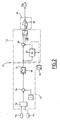
- the scheme of the compensation unit 34 is illustrated on the Figure 2 .
- This unit comprises a module 42 for calculating the slippage of the strip at the output of the cage 16A, a module 44 for calculating the time variation of sliding of the strip and a unit 46 for producing a speed correction signal. of rotation of the only cylinders of the first cage 16A.
- the slip calculation module 42 comprises a divider 52 capable of ensuring the division of the linear speed V s1 of the band at the output of the first cage 16A by the circumferential speed V c1 of the cylinders of the first cage delivered by the sensor 36.
- a subtractor 54 subtracts the number 1 from the quotient of the velocities.
- the calculation module 42 has at its output a filter 58 making it possible to filter the measurement of the slip g 1 .
- the module 44 for calculating the sliding time variation ⁇ g1 comprises a memory 62 capable of storing an initial filtered slip value g ii produced by the module 42 during the start-up of the unit 34.
- a trigger 64 is able to ensure the storage of the current slip value produced by the module 42 during the startup of the unit.
- the module 44 further comprises a subtracter 66 able to make the difference between the current filtered slip g 1 obtained at the output of the module 42 and the value of the initial filtered slip g 1 i stored in the memory 62.
- a slip variation ⁇ g 1 g 1 - g 1i in the cage 16A is thus obtained.
- the unit 46 in this embodiment is able to ensure the adjustment of the relative speed correction of the unit 34. In theory this gain is -1.
- the output of the unit 46 is connected to a multiplier 69A provided at the output of the speed regulator 30A.
- the output of the multiplier supplies the speed reference value u A to the drive motor of the cylinders 18.
- the multiplier is able to multiply the setpoint u 3A by (1 + u 2A ).
- the speed instruction u 1A is increased or decreased in percentage by an amount equal to the opposite of the sliding variation ⁇ g 1 at the moment of measurement considered.
- This installation further comprises a sensor 138 for measuring the rotation speed V C2 of the drive motors of the cage 16B making it possible to measure the instantaneous circumferential speed of the working rolls of the second cage 16B.
- This sensor is connected to the supplementary compensation unit 34.
- the unit 34 has two outputs, one connected to the multiplier 69A and a second connected to a second multiplier 69B integrated in the speed controller 30B.
- the second output of the additional compensation unit 34 is adapted to provide an additional correction u 2B addressed to the multiplier 69B to output a speed reference value u B applied to the engine of the second cage 16B.
- the additional compensation unit 34 has an output u 2C for controlling the clamping position of the rollers of the third cage 16C.
- the diagram of the supplementary correction unit 34 is illustrated on the Figure 4 .
- This diagram shows the modules 42 and 44 of the first embodiment.
- the module 70 comprises a divider 76 capable of calculating the transfer time t 23 of a point of the band B between the second and third cages from the distance d 23 separating these cages from the speed V S2 of circulation of the bandaged.
- an adder 78 connected to a memory 80 for storing a delay constant ⁇ corresponding to the propagation time of the slip filter 58.
- the output of the module 70 is connected to a delay line 82 integrated in the correction module 46.
- This delay line receives as input the signal - ⁇ g 1 obtained at the output of the multiplier 68.
- the delay line 82 is adapted to ensure the application of an additional correction signal u 2A , u 2B to the cages 16A and 16B with the delay produced by the module 70.
- the output of the delay line 82 is applied to both multipliers 69A, 69B so that the speed setpoints u A, u B are each corrected in relative percentage of an amount equal to - ⁇ ⁇ boy Wut 1 ⁇ t + t 23 - ⁇ or t is the moment of measurement,, t 23 is the transfer time between cages 16A and 16B, and ⁇ is the propagation time of the slip filter 58.
- the role of the module 47 is to maintain the traction between the stands 16B and 16C by calculating a clamping correction u 2C for the cage 16C from the speed correction u 2B .
- the output of the module 82 is filtered by the module 90 to ensure an adaptation of the motor dynamics of the cage 16B with respect to the clamping of the cage 16C.
- a gain G 91 is applied by a module 91 on the output signal of the module 90 to ensure that the variation of the clamping position u 2c of the cage 16C is just necessary to compensate for the variation in traction induced by u 2B .
- the first and second cages have their rotational speed of the cylinders corrected to take account of the sliding variations ⁇ g 1 at the outlet of the first cage so that the variation in thickness that may have occurred at the outlet of the second cage with respect to a theoretical optimal thickness is compensated during the passage of the band in the third cage 16C.
- the process according to the invention can be extended to more than two successive cages, the speed of the rolls of all the cages or of only a partial number of cages except the last one being able to be corrected of the same relative quantity and taking into account the transfer time of the product between the second cage and the last corrected cage, so that the last corrected cage compensates for the variation in thickness caused by sliding variations at the outlet of the first cage.
- the inertia compensation unit 32 further receives the speed correction u 1A of the regulator 30A as is usually known and the additional speed correction u 2A obtained taking into account the correction of the unit 34 so that the flow variations at the entrance of the cage 16A can be compensated by means of the traction maintenance system at the input of the rolling mill, this having the purpose of not disturbing the traction at the entrance of the cage 16A.
- the units 30A, 30B and 34 are distinct. However, alternatively, these units are functionally implemented by one and the same computer.
- the inertia compensations are applied to the winder.
Landscapes
- Engineering & Computer Science (AREA)
- Mechanical Engineering (AREA)
- Control Of Metal Rolling (AREA)
Claims (13)
- Verfahren zur Kontrolle des Kaltwalzens eines Blechbands (B), umfassend den kontinuierlichen Durchlauf des Bands in der Kälte durch mindestens zwei aufeinanderfolgende Gehäuse (16A, 16B, 16C, 16D, 16E), die jeweils mindestens zwei Zylinder (18) umfassen, zwischen denen das Band (B) vorgeschoben zirkuliert und ein Breitdrücken erfährt,
dadurch gekennzeichnet, dass es folgendes umfasst:- die Abschätzung der Schlupfschwankung (Δg1) am Ausgang eines Gehäuses (16A); und- die Korrektur der Rotationsgeschwindigkeit (UA; UA, UB) der Zylinder (18) von mindestens einem korrigierten Gehäuse (16A; 16A, 16B) in Funktion der Variation der abgeschätzten Schlupfschwankung (Δg1). - Verfahren nach Anspruch 1, dadurch gekennzeichnet, dass das Verfahren die Dicke des Bands kontrolliert.
- Verfahren nach Anspruch 1 oder 2, dadurch gekennzeichnet, dass die Abschätzung der Schlupfschwankung einen Schritt des Messens der linearen Geschwindigkeit (Vs1) des Bands am Ausgang des Gehäuses und einen Schritt des Abschätzens der Umfangsgeschwindigkeit (Vc1) der Zylinder in dem Gehäuse (16A), und einen Schritt der Berechnung des Schlupfs (g1) des Bands aus der linearen Geschwindigkeit (Vs1) des Bands am Ausgang des Gehäuses (16A) und der Umfangsgeschwindigkeit (Vc1) der Zylinder des Gehäuses umfasst.
- Verfahren nach einem der vorhergehenden Ansprüche, dadurch gekennzeichnet, dass die Abschätzung der Schlupfschwankung am ersten Gehäuse (16A) unter Berücksichtigung der Zirkulationsrichtung des Bands vorgenommen wird.
- Verfahren einem der vorhergehenden Ansprüche, dadurch gekennzeichnet, dass die Korrektur der Geschwindigkeit (UA, UB) auf eine Gesamtheit von mindestens zwei aufeinanderfolgenden Gehäusen (16A, 16B) unter Berücksichtigung der Zirkulationsrichtung des Bands angewandt wird.
- Verfahren nach Anspruch 5, dadurch gekennzeichnet, dass die auf zwei aufeinanderfolgende Gehäuse (16A, 16B) angewandten Korrekturen von Geschwindigkeit (UA, UB) identisch sind.
- Verfahren nach einem der vorhergehenden Ansprüche, dadurch gekennzeichnet, dass die Korrektur der Geschwindigkeit (UA) eine Variation der Geschwindigkeit des im Wesentlichen zum Zeitpunkt der Abschätzung der Schlupfschwankung korrigierten Gehäuses umfasst.
- Verfahren nach einem der Ansprüche 1 bis 6, dadurch gekennzeichnet, dass die Korrektur der Geschwindigkeit eine Variation der Geschwindigkeit des ersten Gehäuses, korrigiert um eine Zeitverschiebung (t23) entsprechend der Übergangszeit des Bands zwischen dem letzten korrigierten Gehäuse (16B) und dem folgenden Gehäuse (16C) unter Berücksichtigung der Zirkulationsrichtung des Bands umfasst.
- Verfahren nach Anspruch 8, dadurch gekennzeichnet, dass die zeitliche Verschiebung eine Verzögerung (τ) auf Grund einer Filterung integriert.
- Verfahren nach einem der Ansprüche 1 bis 6, dadurch gekennzeichnet, dass die Korrektur der Geschwindigkeit eine Variation der Geschwindigkeit des ersten Gehäuses, korrigiert um eine Zeitverschiebung (t23 + t34) entsprechend der Übergangszeit des Bands zwischen dem Gehäuse, das auf das Gehäuse, an dem die Schlupfschwankung abgeschätzt wird, folgt, und dem ersten, unter Berücksichtigung der Zirkulationsrichtung des Bands korrigierten Gehäuses umfasst.
- Verfahren nach einem der vorhergehenden Ansprüche, dadurch gekennzeichnet, dass eine Presskorrektur auf mindestens ein Gehäuse angewandt wird, das an ein zum Aufrechterhalten des Zugs korrigiertes Gehäuse angrenzt.
- Verfahren nach einem der vorhergehenden Ansprüche, dadurch gekennzeichnet, dass es die Steuerung einer Haltevorrichtung (12) des Zugs umfasst, die stromaufwärts von dem ersten Gehäuse angeordnet ist, und dadurch dass die Steuerung die abgeschätzte Schlupfschwankung berücksichtigt.
- Verfahren zur Kontrolle des Kaltwalzens eines Blechbands (B), umfassend mindestens zwei aufeinanderfolgende Gehäuse (16A, 16B, 16C, 16D, 16E), umfassend jeweils mindestens zwei Zylinder (18), zwischen denen das Band (B) vorgeschoben kalt zirkuliert und ein Breitdrücken erfährt,
dadurch gekennzeichnet, dass es folgendes umfasst:- Mittel (34) zur Abschätzung der Schlupfschwankung (Δg1) am Ausgang eines Gehäuses (16A);- Mittel (30A, 34) zur Korrektur der Rotationsgeschwindigkeit (UA; UA, UB) der Zylinder (18) von mindestens einem korrigierten Gehäuse (16A; 16A, 16B) in Funktion der abgeschätzten Schlupfschwankung (Δg1), und- Mittel zur Durchführung eines Verfahrens nach einem der vorhergehenden Ansprüche.
Applications Claiming Priority (2)
| Application Number | Priority Date | Filing Date | Title |
|---|---|---|---|
| FR0602229A FR2898523B1 (fr) | 2006-03-14 | 2006-03-14 | Procede de laminage d'une bande de tole. |
| PCT/FR2007/000443 WO2007104865A1 (fr) | 2006-03-14 | 2007-03-14 | Procede de laminage d'une bande de tole |
Publications (2)
| Publication Number | Publication Date |
|---|---|
| EP1996347A1 EP1996347A1 (de) | 2008-12-03 |
| EP1996347B1 true EP1996347B1 (de) | 2010-12-15 |
Family
ID=37307329
Family Applications (1)
| Application Number | Title | Priority Date | Filing Date |
|---|---|---|---|
| EP07731138A Revoked EP1996347B1 (de) | 2006-03-14 | 2007-03-14 | Verfahren zum walzen eines blechbands |
Country Status (7)
| Country | Link |
|---|---|
| US (1) | US8347681B2 (de) |
| EP (1) | EP1996347B1 (de) |
| CN (1) | CN101454091B (de) |
| DE (1) | DE602007011224D1 (de) |
| ES (1) | ES2361456T3 (de) |
| FR (1) | FR2898523B1 (de) |
| WO (1) | WO2007104865A1 (de) |
Cited By (1)
| Publication number | Priority date | Publication date | Assignee | Title |
|---|---|---|---|---|
| CN110314941A (zh) * | 2019-08-07 | 2019-10-11 | 中铝瑞闽股份有限公司 | 一种铝合金热轧梯度张力控制的生产方法 |
Families Citing this family (5)
| Publication number | Priority date | Publication date | Assignee | Title |
|---|---|---|---|---|
| US8286171B2 (en) | 2008-07-21 | 2012-10-09 | Workshare Technology, Inc. | Methods and systems to fingerprint textual information using word runs |
| EP2527052A1 (de) * | 2011-05-24 | 2012-11-28 | Siemens Aktiengesellschaft | Betriebsverfahren für eine Walzstraße |
| US9613340B2 (en) | 2011-06-14 | 2017-04-04 | Workshare Ltd. | Method and system for shared document approval |
| KR102110645B1 (ko) * | 2013-12-24 | 2020-05-14 | 아르셀러미탈 | 열간 압연 방법 |
| DE102019132133A1 (de) * | 2019-11-27 | 2021-05-27 | Muhr Und Bender Kg | Anlage und verfahren zum flexiblen walzen von metallischem bandmaterial |
Family Cites Families (15)
| Publication number | Priority date | Publication date | Assignee | Title |
|---|---|---|---|---|
| FR2395086A1 (fr) * | 1977-06-24 | 1979-01-19 | Siderurgie Fse Inst Rech | Procede de controle de la tension de produits epais lamines a chaud en prise entre deux cages successives |
| JPS6188911A (ja) * | 1984-10-05 | 1986-05-07 | Nippon Steel Corp | タンデム圧延における自動板厚制御方法 |
| US4745556A (en) * | 1986-07-01 | 1988-05-17 | T. Sendzimir, Inc. | Rolling mill management system |
| US4907433A (en) * | 1988-04-18 | 1990-03-13 | Bethlehem Steel Corporation | Apparatus and method for adaptive control of a rolling mill |
| US5012660A (en) * | 1989-11-29 | 1991-05-07 | Aeg Westinghouse Industrial Automation Corporation | Control system and method for compensating for speed effect in a tandem cold mill |
| JP2850496B2 (ja) * | 1990-06-27 | 1999-01-27 | 日本鋼管株式会社 | 冷間圧延機のスリップ抑制方法 |
| CN1050783C (zh) * | 1995-10-20 | 2000-03-29 | 冶金工业部钢铁研究总院 | 热带连轧机恒张力控制和连轧厚度及截面积计算方法 |
| JP2000094022A (ja) * | 1998-09-14 | 2000-04-04 | Toshiba Corp | 通板速度制御装置 |
| JP2000167612A (ja) * | 1998-12-04 | 2000-06-20 | Toshiba Corp | 圧延機の最適パススケジュール決定方法及び装置 |
| JP2000288614A (ja) * | 1999-04-09 | 2000-10-17 | Toshiba Corp | 圧延機の板厚制御装置 |
| FR2792857B1 (fr) * | 1999-04-28 | 2001-07-27 | Kvaerner Metals Clecim | Procede de fabrication, en continu, d'une bande metallique |
| US6167736B1 (en) * | 1999-07-07 | 2001-01-02 | Morgan Construction Company | Tension control system and method for reducing front end and tail end overfill of a continuously hot rolled product |
| US6263714B1 (en) * | 1999-12-27 | 2001-07-24 | Telepro, Inc. | Periodic gauge deviation compensation system |
| JP2005340867A (ja) | 2003-03-18 | 2005-12-08 | Fuji Xerox Co Ltd | ファクシミリ装置 |
| US20070068210A1 (en) * | 2005-09-29 | 2007-03-29 | University Of Pittsburgh - Of The Commonwealth System Of Higher Education | System for controlling a rolling mill and method of controlling a rolling mill |
-
2006
- 2006-03-14 FR FR0602229A patent/FR2898523B1/fr not_active Expired - Fee Related
-
2007
- 2007-03-14 US US12/225,033 patent/US8347681B2/en not_active Expired - Fee Related
- 2007-03-14 EP EP07731138A patent/EP1996347B1/de not_active Revoked
- 2007-03-14 ES ES07731138T patent/ES2361456T3/es active Active
- 2007-03-14 DE DE602007011224T patent/DE602007011224D1/de active Active
- 2007-03-14 WO PCT/FR2007/000443 patent/WO2007104865A1/fr not_active Ceased
- 2007-03-14 CN CN2007800133444A patent/CN101454091B/zh not_active Expired - Fee Related
Cited By (1)
| Publication number | Priority date | Publication date | Assignee | Title |
|---|---|---|---|---|
| CN110314941A (zh) * | 2019-08-07 | 2019-10-11 | 中铝瑞闽股份有限公司 | 一种铝合金热轧梯度张力控制的生产方法 |
Also Published As
| Publication number | Publication date |
|---|---|
| WO2007104865A1 (fr) | 2007-09-20 |
| FR2898523B1 (fr) | 2009-02-27 |
| DE602007011224D1 (de) | 2011-01-27 |
| US20090235706A1 (en) | 2009-09-24 |
| ES2361456T3 (es) | 2011-06-17 |
| EP1996347A1 (de) | 2008-12-03 |
| CN101454091B (zh) | 2013-03-06 |
| CN101454091A (zh) | 2009-06-10 |
| US8347681B2 (en) | 2013-01-08 |
| FR2898523A1 (fr) | 2007-09-21 |
Similar Documents
| Publication | Publication Date | Title |
|---|---|---|
| EP3086889B1 (de) | Heisswalzverfahren, heisswalzwerk und computerprogramm zur durchführung eines solchen verfahrens | |
| EP2167248B1 (de) | Verfahren zur walzung eines metallbandes mit einstellung der seitlichen position des bandes und dafür geeignetes walzwerk | |
| EP1466675B1 (de) | Verfahren und Vorrichtung zur Dickenregelung eines gewalzten Produktes | |
| EP1996347A1 (de) | Verfahren zum walzen eines blechbands | |
| US6263714B1 (en) | Periodic gauge deviation compensation system | |
| EP1020240B1 (de) | Verfahren zur Zug-/Druckregelung in einem Vielständer-Warmwalzwerk und entsprechendes Regelungssystem | |
| FR2585486A1 (fr) | Appareil de commande de vitesses pour un appareillage de traitement en continu de toles d'acier | |
| KR20150020061A (ko) | 압연 제어 장치, 압연 제어 방법 및 기록 매체 | |
| EP0041025B1 (de) | Verfahren und Vorrichtung zum Walzen von Metall ohne Walzgutspannung | |
| EP2958687B1 (de) | Verfahren zum walzen eines blechstreifens | |
| CH677373A5 (de) | ||
| FR2469963A1 (fr) | Installation de reglage pour un laminoir d'etirage et de reduction a cages multiples destine a des tubes | |
| EP2172282B1 (de) | Verfahren zur Steuerung des Walzens eines Blechbandes | |
| EP2464470B1 (de) | Verfahren und vorrichtung für die automatische einstellung der position von arbeitswalzen bei einer walzanlage | |
| EP0000454B1 (de) | Verfahren zum Steuern der Walzgutspannung zwischen aufeinanderfolgenden Walzgerüsten beim Warmwalzen von dickem Walzgut. | |
| EP2938476B1 (de) | Verfahren und vorrichtung zur regelung einer extrusionsvorrichtung | |
| EP0000855B2 (de) | Verfahren zum Vorsteuern von einer kontinuierlichen Tandemstrasse beim Warmwalzen von Metall | |
| EP0560688A1 (de) | Regelungsvorrichtung eines Kaltbearbeitungswerkzeuges zum Nachwalzen von Blech | |
| EP1782953B1 (de) | Verfahren und Vorrichtung zum Einstellen der Farbzufuhrmenge eines Druckprodukts | |
| EP2349598A1 (de) | Vorrichtung und verfahren zur einstellung einer anlage zur umwandlung eines stahlbands als funktion einer willkürlichen dicke des stahlbands | |
| FR2878174A1 (fr) | Procede de fabrication d'un fil plat par laminage a froid | |
| FR2464106A1 (fr) | Dispositif pour la regulation automatique de la forme de bandes en cours de laminage | |
| FR2473915A1 (fr) | Procede et dispositif de regulation de l'epaisseur d'un lamine | |
| BE731620A (de) | ||
| JPS6199507A (ja) | 圧延制御方法 |
Legal Events
| Date | Code | Title | Description |
|---|---|---|---|
| PUAI | Public reference made under article 153(3) epc to a published international application that has entered the european phase |
Free format text: ORIGINAL CODE: 0009012 |
|
| 17P | Request for examination filed |
Effective date: 20080911 |
|
| AK | Designated contracting states |
Kind code of ref document: A1 Designated state(s): DE ES FR |
|
| DAX | Request for extension of the european patent (deleted) | ||
| RBV | Designated contracting states (corrected) |
Designated state(s): DE ES FR |
|
| GRAP | Despatch of communication of intention to grant a patent |
Free format text: ORIGINAL CODE: EPIDOSNIGR1 |
|
| GRAS | Grant fee paid |
Free format text: ORIGINAL CODE: EPIDOSNIGR3 |
|
| GRAA | (expected) grant |
Free format text: ORIGINAL CODE: 0009210 |
|
| AK | Designated contracting states |
Kind code of ref document: B1 Designated state(s): DE ES FR |
|
| REF | Corresponds to: |
Ref document number: 602007011224 Country of ref document: DE Date of ref document: 20110127 Kind code of ref document: P |
|
| REG | Reference to a national code |
Ref country code: ES Ref legal event code: FG2A Ref document number: 2361456 Country of ref document: ES Kind code of ref document: T3 Effective date: 20110617 |
|
| PLBI | Opposition filed |
Free format text: ORIGINAL CODE: 0009260 |
|
| PLAX | Notice of opposition and request to file observation + time limit sent |
Free format text: ORIGINAL CODE: EPIDOSNOBS2 |
|
| 26 | Opposition filed |
Opponent name: SMS SIEMAG AG Effective date: 20110915 |
|
| REG | Reference to a national code |
Ref country code: DE Ref legal event code: R026 Ref document number: 602007011224 Country of ref document: DE Effective date: 20110915 |
|
| PLAF | Information modified related to communication of a notice of opposition and request to file observations + time limit |
Free format text: ORIGINAL CODE: EPIDOSCOBS2 |
|
| PLBB | Reply of patent proprietor to notice(s) of opposition received |
Free format text: ORIGINAL CODE: EPIDOSNOBS3 |
|
| RAP2 | Party data changed (patent owner data changed or rights of a patent transferred) |
Owner name: GE ENERGY POWER CONVERSION FRANCE SAS |
|
| PGFP | Annual fee paid to national office [announced via postgrant information from national office to epo] |
Ref country code: FR Payment date: 20140317 Year of fee payment: 8 Ref country code: ES Payment date: 20140326 Year of fee payment: 8 |
|
| PGFP | Annual fee paid to national office [announced via postgrant information from national office to epo] |
Ref country code: DE Payment date: 20140327 Year of fee payment: 8 |
|
| RDAF | Communication despatched that patent is revoked |
Free format text: ORIGINAL CODE: EPIDOSNREV1 |
|
| REG | Reference to a national code |
Ref country code: DE Ref legal event code: R103 Ref document number: 602007011224 Country of ref document: DE Ref country code: DE Ref legal event code: R064 Ref document number: 602007011224 Country of ref document: DE |
|
| RDAG | Patent revoked |
Free format text: ORIGINAL CODE: 0009271 |
|
| STAA | Information on the status of an ep patent application or granted ep patent |
Free format text: STATUS: PATENT REVOKED |
|
| 27W | Patent revoked |
Effective date: 20141006 |
|
| REG | Reference to a national code |
Ref country code: DE Ref legal event code: R107 Ref document number: 602007011224 Country of ref document: DE Effective date: 20150319 |