EP1996401B1 - Impression d'images en continu sur un matériau en bande et transfert en continu des images sur des piecès d'identité - Google Patents
Impression d'images en continu sur un matériau en bande et transfert en continu des images sur des piecès d'identité Download PDFInfo
- Publication number
- EP1996401B1 EP1996401B1 EP07757557A EP07757557A EP1996401B1 EP 1996401 B1 EP1996401 B1 EP 1996401B1 EP 07757557 A EP07757557 A EP 07757557A EP 07757557 A EP07757557 A EP 07757557A EP 1996401 B1 EP1996401 B1 EP 1996401B1
- Authority
- EP
- European Patent Office
- Prior art keywords
- component
- images
- web material
- registration
- Prior art date
- Legal status (The legal status is an assumption and is not a legal conclusion. Google has not performed a legal analysis and makes no representation as to the accuracy of the status listed.)
- Active
Links
Images






Classifications
-
- B—PERFORMING OPERATIONS; TRANSPORTING
- B42—BOOKBINDING; ALBUMS; FILES; SPECIAL PRINTED MATTER
- B42D—BOOKS; BOOK COVERS; LOOSE LEAVES; PRINTED MATTER CHARACTERISED BY IDENTIFICATION OR SECURITY FEATURES; PRINTED MATTER OF SPECIAL FORMAT OR STYLE NOT OTHERWISE PROVIDED FOR; DEVICES FOR USE THEREWITH AND NOT OTHERWISE PROVIDED FOR; MOVABLE-STRIP WRITING OR READING APPARATUS
- B42D25/00—Information-bearing cards or sheet-like structures characterised by identification or security features; Manufacture thereof
- B42D25/40—Manufacture
- B42D25/48—Controlling the manufacturing process
-
- B—PERFORMING OPERATIONS; TRANSPORTING
- B41—PRINTING; LINING MACHINES; TYPEWRITERS; STAMPS
- B41J—TYPEWRITERS; SELECTIVE PRINTING MECHANISMS, i.e. MECHANISMS PRINTING OTHERWISE THAN FROM A FORME; CORRECTION OF TYPOGRAPHICAL ERRORS
- B41J2/00—Typewriters or selective printing mechanisms characterised by the printing or marking process for which they are designed
- B41J2/315—Typewriters or selective printing mechanisms characterised by the printing or marking process for which they are designed characterised by selective application of heat to a heat sensitive printing or impression-transfer material
- B41J2/32—Typewriters or selective printing mechanisms characterised by the printing or marking process for which they are designed characterised by selective application of heat to a heat sensitive printing or impression-transfer material using thermal heads
- B41J2/325—Typewriters or selective printing mechanisms characterised by the printing or marking process for which they are designed characterised by selective application of heat to a heat sensitive printing or impression-transfer material using thermal heads by selective transfer of ink from ink carrier, e.g. from ink ribbon or sheet
-
- B—PERFORMING OPERATIONS; TRANSPORTING
- B42—BOOKBINDING; ALBUMS; FILES; SPECIAL PRINTED MATTER
- B42D—BOOKS; BOOK COVERS; LOOSE LEAVES; PRINTED MATTER CHARACTERISED BY IDENTIFICATION OR SECURITY FEATURES; PRINTED MATTER OF SPECIAL FORMAT OR STYLE NOT OTHERWISE PROVIDED FOR; DEVICES FOR USE THEREWITH AND NOT OTHERWISE PROVIDED FOR; MOVABLE-STRIP WRITING OR READING APPARATUS
- B42D25/00—Information-bearing cards or sheet-like structures characterised by identification or security features; Manufacture thereof
-
- B—PERFORMING OPERATIONS; TRANSPORTING
- B42—BOOKBINDING; ALBUMS; FILES; SPECIAL PRINTED MATTER
- B42D—BOOKS; BOOK COVERS; LOOSE LEAVES; PRINTED MATTER CHARACTERISED BY IDENTIFICATION OR SECURITY FEATURES; PRINTED MATTER OF SPECIAL FORMAT OR STYLE NOT OTHERWISE PROVIDED FOR; DEVICES FOR USE THEREWITH AND NOT OTHERWISE PROVIDED FOR; MOVABLE-STRIP WRITING OR READING APPARATUS
- B42D25/00—Information-bearing cards or sheet-like structures characterised by identification or security features; Manufacture thereof
- B42D25/20—Information-bearing cards or sheet-like structures characterised by identification or security features; Manufacture thereof characterised by a particular use or purpose
- B42D25/23—Identity cards
-
- B—PERFORMING OPERATIONS; TRANSPORTING
- B65—CONVEYING; PACKING; STORING; HANDLING THIN OR FILAMENTARY MATERIAL
- B65H—HANDLING THIN OR FILAMENTARY MATERIAL, e.g. SHEETS, WEBS, CABLES
- B65H23/00—Registering, tensioning, smoothing or guiding webs
- B65H23/04—Registering, tensioning, smoothing or guiding webs longitudinally
- B65H23/18—Registering, tensioning, smoothing or guiding webs longitudinally by controlling or regulating the web-advancing mechanism, e.g. mechanism acting on the running web
- B65H23/188—Registering, tensioning, smoothing or guiding webs longitudinally by controlling or regulating the web-advancing mechanism, e.g. mechanism acting on the running web in connection with running-web
- B65H23/1882—Registering, tensioning, smoothing or guiding webs longitudinally by controlling or regulating the web-advancing mechanism, e.g. mechanism acting on the running web in connection with running-web and controlling longitudinal register of web
-
- B—PERFORMING OPERATIONS; TRANSPORTING
- B65—CONVEYING; PACKING; STORING; HANDLING THIN OR FILAMENTARY MATERIAL
- B65H—HANDLING THIN OR FILAMENTARY MATERIAL, e.g. SHEETS, WEBS, CABLES
- B65H23/00—Registering, tensioning, smoothing or guiding webs
- B65H23/04—Registering, tensioning, smoothing or guiding webs longitudinally
- B65H23/18—Registering, tensioning, smoothing or guiding webs longitudinally by controlling or regulating the web-advancing mechanism, e.g. mechanism acting on the running web
- B65H23/188—Registering, tensioning, smoothing or guiding webs longitudinally by controlling or regulating the web-advancing mechanism, e.g. mechanism acting on the running web in connection with running-web
- B65H23/1888—Registering, tensioning, smoothing or guiding webs longitudinally by controlling or regulating the web-advancing mechanism, e.g. mechanism acting on the running web in connection with running-web and controlling web tension
-
- B—PERFORMING OPERATIONS; TRANSPORTING
- B65—CONVEYING; PACKING; STORING; HANDLING THIN OR FILAMENTARY MATERIAL
- B65H—HANDLING THIN OR FILAMENTARY MATERIAL, e.g. SHEETS, WEBS, CABLES
- B65H39/00—Associating, collating, or gathering articles or webs
- B65H39/14—Associating sheets with webs
-
- B—PERFORMING OPERATIONS; TRANSPORTING
- B65—CONVEYING; PACKING; STORING; HANDLING THIN OR FILAMENTARY MATERIAL
- B65H—HANDLING THIN OR FILAMENTARY MATERIAL, e.g. SHEETS, WEBS, CABLES
- B65H2701/00—Handled material; Storage means
- B65H2701/10—Handled articles or webs
- B65H2701/19—Specific article or web
- B65H2701/1914—Cards, e.g. telephone, credit and identity cards
Definitions
- the technical disclosure herein relates to printing images and transferring the images to identity documents in the production thereof.
- identity documents can include for instance plastic cards, which may include financial (e.g. credit and debit) cards, drivers' licenses, national identification cards, or other related identity documents, such as passports, which usually bear personalized data unique to the card holder and/or which bear other card or document information.
- financial e.g. credit and debit
- national identification cards e.g. credit and debit
- passports e.g. credit and debit
- the technical disclosure herein relates to printing images and transferring the images to identity documents on a continuous basis.
- Document WO 99/32291 A1 discloses a system for transferring images to identity documents comprising:
- Identity documents which are often personalized by such systems and methods, may include plastic and composite cards, for instance financial (e.g. credit and debit) cards, drivers' licenses, national identification cards, and other related cards and documents which are personalized with information unique to the intended document holder.
- financial e.g. credit and debit
- Document personalization systems and methods can be designed for small scale, individual document personalization and production.
- a single document to be personalized is input into a personalization machine, which typically includes one or two personalization/production capabilities, such as printing and film application through heat transfer.
- Improvements may be made upon existing personalization/production stations, namely heat transfer printing and application modules. Particularly, improvements may be made on such modules that can provide increased throughput and efficiency.
- the technical disclosure described below can provide for a system of personalizing identity documents by printing images and applying them to the identity documents, where module timing and positioning may be improved, and while minimizing image and web material waste and document rejection.
- the present disclosure provides for continuous printing and application of images to identity documents.
- the technical disclosure herein is relevant to, among other applications, modular processing of personalized documents, where high speed document processing and throughput are desired.
- the disclosure is further relevant to such applications where document processing and throughput may be desired at a rate of, for example, about 500 identity documents processed/hour or higher.
- the present disclosure provides a system according to claim 1 and a method according to claim 13 of printing and applying images to identity documents where printing, registration and applicator components have simultaneous processing cycles and have simultaneous intervals between processing cycles, such that continuous printing and application of images onto identity documents can occur.
- the present disclosure may achieve efficient production of identity documents by improving system timing and mechanism positioning, while resulting in fewer rejected documents.
- a system for printing images and transferring the images to identity documents includes a web material having a surface that is printable thereon.
- a print component prints images on the web material.
- a registration component registers a select image to an identity document.
- An applicator component applies a selected image to the identity document, after the selected image has been registered with the respective identity document.
- a controller maintains continuous throughput of the web material through the print component, registration component, and applicator component. The controller synchronizes cycles of the components, such that they are configured to have simultaneous processing cycles and have simultaneous intervals between processing cycles.
- the print component prints a plurality of images on the web material.
- the registration component registers select images to a plurality of identity documents.
- the applicator component applies each selected image to one of the identity documents, when the selected image is registered with the respective identity document.
- the controller maintains continuous throughput of the web material through the components, where the controller synchronizes cycles of the components, such that they have simultaneous processing cycles and simultaneous intervals between processing cycles.
- a method for continuously printing images on a web material and transferring the images on the web material to identity documents includes printing a plurality of images on the web material. A select image from the web material is registered to an identity document. The image can then be applied to the identity document that the image is registered with. The steps of printing images, registering select images, and applying the select images are repeated a number of times in a continuous manner, whereby the steps of printing, registration, and application have synchronized cycles, such that the steps have simultaneous processing cycles and have simultaneous intervals between processing cycles.
- a system for printing and applying images to identity documents includes an assembly for maintaining tension in a web material.
- the assembly includes a support body with a displacement arm mounted on the support body.
- the displacement arm is receivable for supporting a web material at an initial tension on the displacement arm.
- the displacement arm is movable in a first direction when an increased tension is applied from one side, and is movable in a second direction when a decreased tension is applied from another side.
- a detector component is mounted on the support body, and is operatively connected with the displacement arm.
- the detector component can detect a transition through movement of the displacement arm and indicated by increased or decreased tension on the displacement arm.
- the transition detected by the detector component is readable for making tension and velocity adjustments on the web material, so as to maintain uniform tension and constant velocity.
- Figure 1 represents one exemplary embodiment of a system 10 for continuously printing images and transferring the images to, for example, identity documents in the production of personalized identity documents.
- the system 10 includes a print component 12, a registration component 14, and an applicator component 16.
- the print, registration, and applicator components cooperate to continuously print images and transfer images to identity documents, by having simultaneous processing cycles and simultaneous intervals between processing cycles.
- the print component 12 prints images on a web material 19.
- the web material 19 is provided with a surface for printing thereon.
- the web material 19 is delivered to the print component 12 from a supply component 13.
- the supply component 13 may be a supply roll and spindle assembly as known in the art or any other suitable structure for supplying a run of the web material 19 to the print component 12.
- the print component 12 prints images on the web material 19. Once images have been printed on the web material 19, the web material 19 and the images printed thereon are delivered to a registration component 14.
- the registration component 14 registers select images on the web material to documents, such as identity document 20.
- the registration component 14 assures that each selected image is correctly registered with a respective identity document before the image is applied to its identity document 20 with the applicator component 16. That is, the identity document 20 and the selected image on the web material 19 are paired and positioned, so that they simultaneously enter the applicator component 16 for the select image to be applied to the identity document.
- the applicator component 16 applies each selected image from the web material 19 to its respective identity document 20.
- the applicator component 16 applies the image to the identity document once the image is registered with its respective document.
- the take-up component 15 may be a take-up roll and spindle assembly as known in the art or any other suitable structure that can take-up used web material after application.
- Transport members 17 facilitate throughput of the web material 19 through the system and the components 12, 14, and 16. It will be appreciated that the transport members 17 may be transport rollers as known in the art or any other suitable structure for facilitating delivery of the web material 19 through the system 10.
- one identity document 20 is shown being processed through the system 10. It will be appreciated that continuous processing can occur, such that a plurality of images may be continuously printed on the web material 19 and a plurality of selected images may be continuously applied to a plurality of respective identity documents.
- a transport or conveyor as known in the art (not shown) can deliver a plurality of documents successively (such as a plurality of identity documents 20) to the registration component 14.
- a controller 11 is operatively connected with the print component 12, registration component 14, and applicator component 16 for transferring data information and instructions for operating the components.
- the controller 11 maintains continuous throughput of the web material 19 through the system 10 to continuously print images and apply select printed images from the web material to identity documents.
- the controller 11 synchronizes operation cycles of the components 12, 14, and 16, such that the components have simultaneous processing cycles and have simultaneous intervals between processing cycles.
- the controller 11 may be a CPU that controls the print, registration, and applicator components through suitably constructed firmware configurations, or in other examples, as suitable computer programs contained permanently in a hardware device as read-only memory.
- the controller includes control firm ware that can enable the system 10 to simultaneously perform the functions of printing, registration, and application, so as to provide continuous (non-stop) document processing.
- a document immediately preceding the document in the applicator component 16 can be retrieved, such as by a document conveyor (not shown), and positioned by the registration component 14 with a select image from the web material, while the print component 12 prints images on the web material 19.
- a document conveyor may be any structure or mechanism known in the art and that is suitable for carrying and/or transporting the identity documents to the registration component.
- a document may be simultaneously processed in a module immediately upstream or downstream of the system 10.
- the registration component 14 includes a mechanism 14b that registers and feeds identity documents into the applicator component 16.
- the registration component 14 also includes a mechanism 14a that examines the web material 19 by looking for a registration mark of the next select image. On detection of the web registration mark, the respective identity document and image are registered, such that they are paired and positioned to be simultaneously fed into the applicator component 16, where the image can be applied to the identity document. It will be appreciated that some images may not be selected by the registration component, and are for example "passed over,” where such images run through the registration and applicator components to the take-up without being applied to an identity document.
- the system includes a tension adjustment mechanism 18.
- the tension adjustment mechanism 18 is configured to maintain constant velocity and uniform tension of the web material within and between components of the system 10. An example of a tension adjustment mechanism is further discussed in Figures 15-17 below.
- the system 10 includes component spacing in such a manner that if an error occurs, for example, the current identity document in the applicator component 16 is not rejected and the existing images on the web material 19 can be saved.
- an error such as upstream of the printer component 12, between any of the print component 12, registration component 14, and applicator component, or downstream of the applicator component 16, the next image application cycle will not be initiated.
- the web 19, and components 12, 14, 16 are stopped.
- the web material 19 may then be reversed to a recovery (restart) position.
- the components of the system 10 remain idle or in a non-active interval between processing cycles, until the reported error condition has been repaired. When the error condition has been repaired, the printing, registration, and application cycles can be resumed to simultaneous and continuous processing.
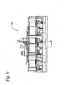
- Figures 2 through 6 illustrate another embodiment of a system 100 for continuously printing images on a web material and transferring the images to documents, such as in personalizing identity documents.
- identity documents is to be broadly construed, and that the following descriptions of cards is exemplary only and employed for purposes of representing one embodiment of the disclosure. It will be further appreciated that such identity documents can include for instance plastic cards, which may include financial (e.g. credit and debit) cards, drivers' licenses, national identification cards, or other related identity documents constructed of various mediums other than cards, such as passports or other identity documents that usually bear personalized data unique to the card holder and/or which bear other document information.
- financial e.g. credit and debit
- the system 100 is similar to the system 10 and including such differences as described herein.
- the system 100 includes a print component 120, a registration component 140, and an applicator component 160.
- the system 100 is supported by a frame structure 112. It will be appreciated that any suitable frame structure may be employed and that the system is not limited to the specific structure shown in the figures, so long as the components of the system are provided with proper support to carry out their functions.
- the print component 120 prints images on a web material 190.
- the web material 190 may be delivered to the print component 120 from a supply roll and spindle assembly 130.
- a guide pin 120c is employed to help support the web material 190 and route it to the print component.
- the web material 190 is provided with a surface, such that images 192 and registration marks 192a disposed at trailing edges of the images 192 are printed on the web material 190 (best shown in Figures 8 through 10 ).
- the images 192 and registration marks 192a will be further described below.
- the web material 190 may be a continuous print media.
- the web material 190 is a pigment receptive carrier onto which the images and registration marks are printed.
- a final print station of the print component 120 can be designated to also apply a thermally activated resin layer to the web material 190 to be subsequently applied to a card.
- the resultant image can be a thin layer thermally transferable from the web material 190 onto the card.
- the thin layer may have a thickness of about 0.5 microns. It will be appreciated that the thin layer may vary as necessary or suitable.
- the web material 190 is constructed so as to allow the image 192 and resin layer (if present) to be released from the web material 190 and be applied onto the card, such as when the image is thermally activated by the applicator 160. That is, the "image material" may be made up of each color pigment printed by the print component and a thermally activated resin layer (or adhesive layer) acting as a primer. The image material is transferred from the web to the identity document, such as by using heat and pressure.
- the web material 190 may be configured such that the gap 194 between printed images may be approximately 0.2 inches.
- a distance from a trailing edge of one image 192 at its registration mark 192a through a gap 194 to the trailing edge (or registration mark) of another image is approximately 3.8 inches.
- the print component 120 may include print heads that are spaced about 3.8 inches dot row to dot row, where the cards on which the images are applied have approximately a 3.375 inch width.
- an image may be overprinted by about 2100 columns (at about 600 columns per inch) for a total distance of about 3.5 inches.
- the registration mark 192a for image registration and identification may be about 0.1 inches wide, so as to leave an inter image gap 194 of about 0.200 inches.
- the system 100 can include component spacing in such a manner that if an error occurs, the current document or card in the applicator component 160 is not rejected and the existing images on the web material 190 can be saved.
- the registration component 140 particularly the web registration mechanism 140a discussed below, and the applicator component 160 can include a component spacing configuration downstream from the print component 120.
- the image to image spacing which may be the 3.8 inches described above, may be used as a repeat length to determine how far downstream the web registration mechanism 140a and applicator component 160 are spaced from each other and spaced from the print component 120.
- the web registration mechanism 140a may be positioned a multiple of this repeat length, such as at three times the repeat length from the last print head of the print component 120.
- the applicator component 160 also may be spaced downstream from the web registration mechanism at a multiple of the repeat length, such as at one repeat length from the web registration component 140a.
- repeat length may vary as necessary for providing suitable component spacing of the system. It will further be appreciated that the repeat length may be predetermined and may vary according to sizing requirements of the overall system 100 and the type identity document being processed or personalized. Likewise, it will be appreciated that the component spacing is not limited to certain multiples of any repeat length employed. It will be further appreciated that components, other than the print, registration, and applicator components, employed in the system 100 can be positioned according to a multiple of a repeat length determined.
- the print component 120 at least one thermal print head assembly 120b may be disposed about a print drum 120a (see Figure 4 ).
- the print component 120 includes a plurality of thermal print heads 120b disposed about the print drum 120a, such as used in multicolor printing (see Figure 2-3 ).
- the print component 120 supports six thermal print heads 120b about the print drum 120a.
- the print component 120 prints at least one image 192 on the web material 190.
- a print drum 120a can include an outer surface with a high friction gripping surface, such as a silicon coated rubber material. It will be appreciated that the print drum 120a may have any suitable coating or adhesive for providing the high friction gripping surface.
- Multicolor printing employing a print drum and multiple thermal print heads is well known, such as in Applicants' issued patent U.S. Patent No. 6,262,755 , and is not further detailed.
- the registration component 140 registers select images 192 to be applied onto cards.
- the registration component 140 includes a web registration mechanism 140a for the web material 190 and a document registration mechanism 140b for the identity document or card.
- the registration component 140 assures that the select images 192 are correctly registered or paired and positioned with a respective card before the image 192 is applied onto the card. That is, the web registration mechanism 140a and the document registration mechanism 140b are configured to position selected images on the web material with respective cards such that each image and card simultaneously enter the applicator component 160.
- An applicator component 160 applies the selected images 192 from the web material 190 to respective cards in succession.
- the applicator component 160 applies the image to the card once the image is registered with its respective card. As described, both the web material having the image and the respective card simultaneously enter the applicator component 16.
- the applicator component 160 applies the select images 192 to cards through a thermal transfer process using heated rollers that is known in the art. As select images are applied to cards, the remaining web material 190 (without the select images) is collected by a take-up roll and spindle assembly 150. Transport rollers 170 facilitate throughput of the web material 190 through the system and the components 120, 140, and 160.
- a controller i.e. controller 11
- the controller can maintain continuous throughput of the web material 190 through the system 100.
- the controller allows the system to continuously print and apply images to the cards, by synchronizing operation cycles of the components 120, 140, and 160, where the components have simultaneous processing cycles and have simultaneous intervals between processing cycles.
- the controller may be a CPU that controls the print, registration and applicator components through suitably constructed firmware configurations.
- the controller includes firmware that can enable the system 100 to simultaneously perform the functions of printing, registration, and application, so to provide continuous card processing.
- a document immediately preceding the document in the applicator component 160 can be retrieved, such as by a document conveyor (not shown), and positioned by the card registration mechanism 140b with a select image from the web material 190, while the print component 120 prints images on the web material 190.
- a document conveyor may be any structure or mechanism known in the art and that is suitable for carrying the identity documents to the registration component.
- a document may be simultaneously processed in a module immediately upstream or downstream of the system 10.
- the card registration mechanism 140b registers and feeds cards into the applicator component 160.
- the web registration mechanism 140a examines the web material 190 by looking for the web registration mark 192a of the next select image 192. On detection of the web registration mark 192, the card and image 192 are registered and fed together into the applicator component 160, so the image 192 can be applied to the card.
- the next application cycle is not initiated.
- the web 190 and the print component 120 including the print drum 120a are stopped, while the thermal print heads 120b are retracted.
- the currently active print cycle and currently active application cycle may complete before the print heads 120b are retracted and the drum 120a is stopped.
- a heated roller retracts to its home position.
- the web material 190 may then be reversed to a recovery (restart) position. See descriptions of Figures 8 through 10 below.
- the components of the system 100 remain idle or in a non-active interval between processing cycles, such as during an error. When the reported error condition has been repaired, the printing, registration, and application cycles can be resumed to simultaneous processing.
- the system 100 enables the cards and the images to be fed into the applicator component on a continuous basis, because the processing and inactive cycles of the print, registration, and applicator components are synchronized. Such a system can reduce the need to reverse the web material unless an error actually occurs. As a result, card processing throughput can be increased, while reducing the number of rejected images and cards due to modular or system errors.
- Figures 7 and 8 through 10 illustrate one embodiment of a print component 120, such as for the system 100 shown above in Figures 2 through 6 .
- the print component 120 includes the print drum 120a with at least one thermal print head 120b disposed about an outer side of the print drum 120a.
- the print drum 120a moves in the production direction during a card processing cycle, in which the print component 120 prints images 192 on the web material 190. (See Figure 7 .)
- the printing process cycle stops at the end of an image panel strip pin 124.
- the drum may then reverse to a gap 194 between images on the web material 190.
- the thermal print heads 120b can engage the print drum 120a starting in one of the gaps 194 between images and normal production can continue. In such a configuration, unfinished images in process may be saved.
- the print component 120 may include a cleaning roller 122. (See e.g. Figures 3 and 7 .) In one embodiment, the cleaning roller 122 may be disposed before each print head 120b so to contact the web material 190 and remove any debris that is present before printing occurs at each print head.
- Figures 8 through 10 depict partial schematic views of a print component in operation, such as print component 120, and show the print component during states where a printing cycle has stopped processing ( Figure 8 ), where the printing cycle is being corrected ( Figure 9 ), and where the printing cycle has resumed ( Figure 10 ).
- a controller is operatively connected with the print component (i.e. controller 11).
- the controller maintains throughput of the web material 190 through the system so that continuous printing and applying of images can occur.
- the controller synchronizes operation cycles of the print, registration, and applicator components, such that the components have simultaneous processing cycles and have simultaneous intervals between processing cycles, such as when there is an error in the system.
- the controller may be a CPU that controls the components through suitably constructed firm ware configurations, of which the operation of the print component is described below.
- the starting and stopping of the drum and web or retransfer material represent a key element in thermal printing, since this technology has overcome the thermal problems experienced by dye sublimation/thermal transfer technology.
- the print component 120 enables printing to be stopped and restarted, without thermal artifacts in the image (such as optical density shifts).
- the print heads start a print cycle at the same time.
- a primer head begins printing the primer canvas of a first image
- a yellow head begins printing the yellow canvas of a second image
- a magenta head begins printing the magenta canvas of a third image
- a cyan head begins printing the cyan canvas of a fourth image.
- the number of print heads is exemplary only.
- a print component may include additional or less print heads disposed about the print drum. As shown, the print component 120 includes six thermal print heads.
- the controller determines if the print drum of the print component needs to be stopped due to a detected functional error, for example a print component error, an applicator component error and/or a card transport error (including a registration component error).
- a detected functional error for example a print component error, an applicator component error and/or a card transport error (including a registration component error).
- the controller retrieves and stores a current rotational position (P d ) of the print drum of the print component, and determines if the applicator component 160 is currently in an active application cycle. (See Figure 8 .) If the applicator component 160 is active, the print component waits until the current application cycle has been completed. Once the applicator component is idle (between images), the print component 120 retracts the thermal print heads 120b from the drum, stops its print ribbons, and stops the print drum 120a (including a retransfer material (RTM) web take-up motor).
- RTM retransfer material
- the distance between images is also included in the summation of steps to give a total steps (D r ) to restart the print component.
- the print drum is reversed past the stored drum position (P d ) a distance determined by the total number of steps (D r ), where the last printed image before the drum stopped is positioned before the position where the print drum stopped (P d ).
- the registration and applicator components 140, 160 do not attempt to initiate their next processing cycles until the error has been reported and the condition rectified. For example, on detection of a stopped print drum 120a, the applicator component 160 returns the heated roller to its home position and waits for the print component 120 to restart.
- the summation or total steps (D r ) is used to restart the print component.
- the web material 190 is moved forward so that the leading edge of the first image printed after the print drum is restarted 192 is positioned at the drum restart position (P r ).
- the error has been reported and rectified and the print component may restart the print cycle by starting the print drum, starting the print ribbons, and dropping the thermal print heads.
- Figures 8-10 show that the distance the print drum reverses is determined by the amount of forward travel that occurs between the completion of printing the final image before stopping and when the drum is physically stopped. This distance can vary due to the applicator component being in an active apply state at the time the print component is to be stopped. Given the variable distance, a configurable reverse distance can be determined that is greater than the time required to get all motors up to slew and the printing initiated. On restarting the print component, the print drum will advance this configurable distance before resuming the print operation. In this configuration, the print operation may continue at the point it would have had printing not been stopped.
- the applicator component 160 can lower its heated rollers and begin the next application cycle. It will be appreciated that while the applicator component 160 is idle, temperature of its heated rollers can be maintained in order to minimize the restart time.
- errors may be experienced on any of the components of the system 100 at any given time.
- the system 100 can handle these error conditions with minimal material waste.
- card handling errors In addition to print errors and application errors, there may be card handling errors, all of which can be asynchronous to one another.
- the starting and stopping of the print drum 120a and web material represent a key element in such thermal printing methodology.
- the print component 120 described can help overcome the thermal problems experienced by dye sublimation/thermal transfer technology, by stopping and restarting printing, so to prevent thermal artifacts in the image (such as optical density shifts).
- rejection of images in process can be reduced, thereby resulting fewer rejected cards and cost savings to card producers and customers.
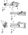
- FIGs 11 through 14 illustrate various embodiments of a tension adjustment mechanism 180, such as for a system 100 shown in Figure 2 .
- Applicator temperature, pressure, card thickness and component wear can affect the linear velocity of a card while it is being processed, such as in the applicator component 160.
- a change in linear velocity can result in a change of web tension.
- Excessive web tension can cause image distortion, wrinkles and poor image geometry.
- Minimal web tension can cause poor image to card registration and web material wrinkles.
- the tension adjustment mechanism 180 described is used to maintain constant velocity and uniform tension of the web material within and between the components of the system 100. It will be appreciated that the tension adjustment mechanism may be used in any application where uniform tension and/or tension adjustments are required in a web material.
- the tension adjustment mechanism 180 includes a support body 182.
- a displacement arm 184 is mounted on the support body 182 and is rotatable with respect to the support body 182.
- the displacement arm 184 is receivable for a web material through a slot 185, such as web material 190.
- the web material is receivable through the displacement arm at an initial tension.
- a guide 188 may be employed to further support the web material and facilitate its travel through the tension adjustment mechanism 180. (See also Figure 2 .)
- the displacement arm 184 can rotate in a first direction when an increased tension is applied from one side, and can rotate in a second direction when a decreased tension is applied from another side.
- a detector component 186 is mounted on the support body 182, and is operatively connected with the displacement arm 184.
- the detector component 186 can detect a transition indicated by the increased or decreased tension on the displacement arm 184, through rotational movement of the displacement arm 184.
- the transition detected by the detector component 186 is readable by a controller (i.e. controller 11) for making tension and velocity adjustments on the web material 190.
- the detector component 186 may be a suitable encoder structure that records transitions indicated by the displacement arm 184.
- the encoder is configured so as to indicate and quantify directional and distance changes of the displacement arm 184.
- the displacement arm 184 may be a spring loaded tension displacement arm that is operatively connected with the encoder.
- the web material 190 is routed through the displacement arm 184 and guide 188 in such a manner that when speed changes occur either upstream or downstream, the displacement arm 184 rotates. Rotation of the arm 184 results in transitions being recorded on the detector component 186.
- the detector component 186 can then be linearized by a controller, and upstream or downstream mechanics can be adjusted to maintain uniform tension and velocity of the web material 190.
- tension is adjusted by varying the speed at the take-up side of the system, such as at the take-up motor.
- the take-up motor speed can be adjusted to maintain the tension mechanism within a certain range of acceptable motion.
- the tension mechanism may be designed (but is not necessary) such that linearity is assumed, where in a linear system the speed of the take-up motor would increase or decrease a fixed amount based on the difference in encoder positions taken between two fixed time samples. It will be appreciated, however, that a non-linear controller algorithm could be implemented that increases/decreases the take-up motor by a variable value based on the amount of tension change between fixed time samples.
- a controller i.e. controller 11 maintains throughput of the web material 190 through the system 100.
- the controller synchronizes operation cycles of the components 120, 140, and 160, such that the components have simultaneous processing cycles and have simultaneous intervals between processing cycles.
- the controller may be a CPU that controls the components through suitably constructed firmware configurations.
- the controller can be operatively connected with the tension adjustment mechanism 180 and detector component 186 to perform the necessary tension adjustment functions discussed above.
- the tension adjustment mechanism 180 compensates for tension differences as well as web stretching that occur due to heat and tension, such as during the application cycle. Variance in web motion between the time the image registration mark has been read and the time the card and web material meet, results in a visible error applying the image to the card. Web variance can be caused by several factors including, but not limited to, slippage on the web take-up capstan rollers, a change in speed of the print drum, heated apply rollers of the applicator component, or the web material itself. Such changes in the web material motion can occur often, such as when the card and web are inserted into the applicator component, and particularly at a nip between the applicator heated rollers.
- the act of heating the web material combined with the tension of pulling the web through the applicator heated rollers can cause the web to stretch. Such stretching may occur as high as about 0.100 inches over 4 inches of web length. This stretching causes error in the web registration unless compensation is made for tension changes.
- a system 200 shows a tension adjustment mechanism 280 in operation.
- an image registration mark of an image i.e. registration mark 192a of an image 192
- the leading edge of the image on the web material 219 can be advanced to meet the document or card 220 it is to be applied at the nip of the heated rollers of the applicator component 260.
- the web material move between a position at the web registration mechanism 240 of the registration component and a position of the heated roller nip of the applicator component 260 is a configurable offset measured in web take-up mechanism motor steps. That is, the web take-up mechanism motor steps or web registration offset (m) represents a configurable distance between the web registration mechanism 240 and the heated roller nip of the applicator component 260.
- the distance between the heated roller of the applicator component and the web material is fixed, and is determined by the mechanical tolerances of the mechanism.
- This distance is represented by a configurable parameter to describe the distance between the leading edge of the image on the web material once the image has been registered (i.e. using the registration bar code).
- the distance between the registration mechanism and the heated roller nip of the applicator component is also a configurable parameter. These values are used to determine, for example, when the print component is to signal placement of the card in the heated roller nip of the applicator component.
- the speed on the take-up side can be used in this calculation in order to determine the amount of time required to move the configured distance to the heated roller nip of the applicator component.
- the range of desirable web tension encoder values can be determined on every power cycle.
- the tension mechanism can be placed in both extreme positions, and the corresponding encoder values read and stored.
- the "ideal" operating encoder range can then be determined by these values.
- the web registration offset (m) is adjusted when the web tension changes.
- a control firmware records a position (d) of the tension adjustment mechanism (i.e. displacement arm), and begins the web registration offset adjustment process.
- the control firmware adjusts the web registration offset (m) by adding additional motor step counts, or subtracting motor step counts based on the relative motion of the tension adjustment mechanism 280 (i.e. displacement arm).
- the web registration offset (m) is decreased according to the amount of tension increase as indicated by the detector component of the web tension mechanism (i.e. detector component 186). If the web tension decreases, as shown in Figure 17 , where the position of the displacement arm 184 is (d+T), then the web take-up speed will have dropped below the print drum speed. In this case, the web registration motor offset (m) is increased accordingly as indicated by the detector component of the web tension mechanism. This adjustment process continues until the web registration offset step count has been exhausted.
- the web registration offset step count which is used to determine when the web material is in position in front of the heated rollers, is decremented or adjusted to zero.
- a card registration mechanism of the registration component can feed the card into the applicator component 260 at the nip of the heated rollers at the same speed as the web, so that the application process can begin.
- the tension adjustment mechanism 280 provides an assembly that is compact and suitable for use in web material handling and to measure relatively small displacements. In this manner, the mechanism 280 helps address issues of variance in web tension and velocity.
- the tension adjustment mechanism 280 described can allow for greater tolerance variations, such as may be caused by variations in drum and applicator roller diameters.
- the tension adjustment mechanism can also compensate for variations in card stock thickness, applicator pressure and temperatures.
- FIGs 18 through 23 illustrate one embodiment of a registration component 140, such as for the system 100 shown in Figure 2 .
- the registration component 140 can provide a high speed precise horizontal and vertical card transport and registration device.
- the registration component 140 includes a web registration mechanism 140a and a card registration mechanism 140b.
- the web registration mechanism 140a may be a laser mechanism 142 that reads the image registration mark of an image to help initiate registration of an image to a card.
- web registration mechanism 140a is disposed between the tension adjustment mechanism 180 and the applicator component 160.
- the card registration mechanism 140b may be a gantry structure that can manipulate a card in x-y directions.
- the card registration mechanism 140b transfers and registers the card with the web material 190 before entry into the applicator component 160.
- the card registration mechanism 140b may be any suitable frame structure raised on side supports so as to span over or around the card.
- Such a gantry card transport contains upper and lower card guides for moving the card in the x-y directions.
- the upper and lower card guides 144, 145 are respectively powered by horizontal and vertical motors 147, 149.
- the lower card guide 145 provides a bias against a card to provide friction and card alignment.
- the lower card guide 145 is spring loaded.
- the lower card guide 145 can help keep the card in place in the gantry while it is being moved in x and/or y directions.
- the gantry can move on horizontal and vertical rails 141, 143 while registering the card to the image on the web material.
- the laser mechanism 142 examines the web looking for the next registration mark. On detection of the web registration mark, the gantry registers the card with a respective image and feeds the card into the applicator component 160 at its heated roller nip to initiate application processing.
- a controller i.e. controller 11
- the controller maintains throughput of the web material 190 through the system 100 to continuously print and apply images to documents.
- the controller synchronizes operation cycles of the components, such that they have simultaneous processing cycles and have simultaneous intervals between processing cycles.
- the controller may be a CPU that controls the components through suitably constructed firmware configurations.
- a controller is used to operate the registration component 140.
- a control firm ware for operation includes standard x/y robotic controls. Such controls may also be used to transport a card across the upper portion of the system 100 in order to pass a card through the system 100 without applying an image to the card.
- the card registration mechanism 140b receives a card from a conveyor mechanism (not shown), and positions the card with speed and accuracy to a designated registration position.
- the card may be made to bypass registration and application.
- a conveyor mechanism is known in the art to deliver documents or cards in within processing modules, and is not further described.
- the web material can be scanned until a selected image for a specified card has been located.
- the control firmware evaluates a time and distance required to move the card into the nip of the heated rollers of the applicator component, as well as a time and distance required to move a leading edge of the image on the web to the nip of the heated rollers.
- the horizontal or "x" motor 147 may then be started at the appropriate time to ensure the card and the leading edge of the image meet at the heated roller nip at the same time, and at the same speed.
- the vertical or "y" motor 149 can adjust the card to match the location of the registration mark read on the image of the web material.
- the card registration mechanism 140b can adjust for rising or falling of the web in the y-axis with respect to the web registration mark read by the web registration mechanism 140a.
- the registration component 140 and namely the card registration mechanism 140b, enables a card to be presented to the applicator component 160 other than by drive rollers. Because the card registration mechanism 140a contains no rollers, it can be formed as a lightweight assembly that can be moved at high speeds and accelerations, while maintaining accuracy and precision in the horizontal and vertical directions.
Landscapes
- Engineering & Computer Science (AREA)
- Manufacturing & Machinery (AREA)
- Electronic Switches (AREA)
- Coloring (AREA)
- Labeling Devices (AREA)
Claims (15)
- Système (10, 100) pour l'impression d'images (192) et le transfert des images sur des pièces d'identité (20, 220), comprenant :un matériau en bande continue (19, 190, 219) ayant une surface pour l'impression d'images (192) sur celui-ci ;un composant d'impression (12, 120) configuré pour imprimer des images sur le matériau en bande continue (19, 190, 219) ;un composant d'enregistrement (14, 140) configuré pour enregistrer des images sélectionnées imprimées sur le matériau en bande continue avec des pièces d'identité (20, 220) ;un composant d'application (16, 160) configuré pour appliquer chaque image sélectionnée sur une des pièces d'identité (20, 220), après que l'image a été enregistrée avec la pièce d'identité (20, 220) ; etun dispositif de commande (11) configuré pour commander le composant d'impression (12, 120), le composant d'enregistrement (14, 140) et le composant d'application (16, 160), de sorte que le système imprime en continu des images (192) et applique en continu des images sur des pièces d'identité (20, 220), le dispositif de commande (11) étant configuré pour synchroniser des cycles du composant d'impression (12, 120), du composant d'enregistrement (14, 140) et du composant d'application (16, 160), de sorte que les composants aient des cycles de traitement simultanés et aient des intervalles simultanés entre des cycles de traitement.
- Système (10, 100) selon la revendication 1, dans lequel le dispositif de commande (11) est configuré pour arrêter l'impression par le composant d'impression (12, 120) sur le matériau en bande continue (19, 190, 219) en présence d'une erreur, inverser le matériau en bande continue (19, 190, 219) à un intervalle (194) sur le matériau en bande continue (19, 190, 219) entre des images (192) et poursuivre l'impression sur le matériau en bande continue (19, 190, 219) une fois que l'erreur a été corrigée.
- Système (10, 100) selon la revendication 2, dans lequel, quand une erreur est présente, le dispositif de commande (11) est configuré pour récupérer et stocker une position (Pd) du composant d'impression (12, 120) et est configuré pour déterminer une distance totale dont le composant d'impression (12, 120) et le matériau en bande continue (19, 190, 219) doivent être inversés au-delà de la position de manière à redémarrer le composant d'impression (12, 120).
- Système (10, 100) selon la revendication 3, dans lequel la distance totale comprend :a) une distance déterminée par un nombre de pas de moteur de tambour d'impression (Da) nécessaire pour accélérer un moteur de tambour d'impression, et
une distance entre des images imprimées (192) sur le matériau en bande continue (19, 190, 219) ; oub) une distance déterminée par un nombre de pas de moteur nécessaire pour positionner des têtes d'impression du composant d'impression (12, 120) ; et
une distance déterminée par un nombre de pas de moteur nécessaire pour accélérer des rubans d'impression du composant d'impression (12, 120). - Système (10, 100) selon la revendication 1, dans lequel le composant d'enregistrement (14, 140) comprend un mécanisme d'enregistrement de bande continue (140a) et un mécanisme d'enregistrement de document (140b).
- Système (10, 100) selon la revendication 5, dans lequel le mécanisme d'enregistrement de bande continue (140a) et le mécanisme d'enregistrement de document (140b) sont configurés pour positionner chaque image sélectionnée (192) avec une pièce d'identité respective (20, 220), de sorte que l'image et la pièce d'identité (20, 220) soient configurées pour entrer simultanément dans le composant d'application (16, 160).
- Système (10, 100) selon la revendication 5, dans lequel le mécanisme d'enregistrement de bande continue (140a) comprend un mécanisme à laser (142) configuré pour lire des marques d'enregistrement d'image (192a) des images imprimées sur le matériau en bande continue (19, 190, 219), et le dispositif de commande (11) est configuré pour déterminer s'il faut sélectionner et enregistrer l'image avec une pièce d'identité (20, 220), sur la base d'une lecture du mécanisme à laser (142).
- Système (10, 100) selon la revendication 5, dans lequel le mécanisme d'enregistrement de document comprend des guides de carte supérieur et inférieur (144, 145) qui sont respectivement mobiles dans des directions x-y et configurés pour déplacer la pièce d'identité (20, 220) dans les directions x-y et enregistrer la pièce d'identité respective (20, 220) avec l'image sélectionnée respective.
- Système (10, 100) selon la revendication 1, comprenant en outre un mécanisme de réglage de tension (18, 180, 280), le mécanisme de réglage de tension étant configuré pour maintenir une vitesse constante et une tension uniforme du matériau en bande continue (19, 190, 219) dans et entre des composants du système.
- Système (10, 100) selon la revendication 1, dans lequel l'image imprimée sur le matériau en bande continue (19, 190, 219) comprend :une image (192) pour l'application sur la pièce d'identité etune marque d'enregistrement (192a) lue par le composant d'enregistrement (14, 140).
- Système (10, 100) selon la revendication 1, comprenant en outre un composant d'espacement entre chacun du composant d'impression (12, 120), du composant d'enregistrement (14, 140) et du composant d'application (16, 160), le composant d'espacement comprend une longueur de répétition ou un multiple de celle-ci, et où, en présence d'une erreur durant le traitement, une pièce d'identité qui est traitée par le composant d'application (16, 160) n'est pas rejetée et des images imprimées sur le matériau en bande continue (19, 190, 219) sont sauvegardées.
- Système (10, 100) selon la revendication 11, dans lequel la longueur de répétition correspond à une longueur d'image à image sur le matériau en bande continue (19, 190,219).
- Procédé pour l'impression en continu d'images (192) sur un matériau en bande continue (19, 190, 219) et le transfert des images sur le matériau en bande continue sur des pièces d'identité (20, 220), comprenant :l'impression d'images (192) sur le matériau en bande continue (19, 190, 219) ;l'enregistrement d'images sélectionnées sur le matériau en bande continue (19, 190, 219) avec des pièces d'identité (20, 220) ;l'application de chaque image sélectionnée (192) sur une des pièces d'identité (20, 220), après que l'image a été enregistrée avec la pièce d'identité respective (20, 220) ; l'exécution en continu des étapes d'impression, d'enregistrement et d'application pour une pluralité d'images sélectionnées (192) et une pluralité de pièces d'identité (20, 220), de sorte que des cycles des étapes d'impression, d'enregistrement et d'application soient synchronisés en ayant des cycles de traitement simultanés et en ayant des intervalles simultanés entre des cycles de traitement.
- Procédé selon la revendication 13, comprenant en outre :la détection d'une erreur de sorte que, quand une erreur est détectée, les cycles de traitement des étapes d'impression, d'enregistrement et d'application soient arrêtés ; etla correction de l'erreur détectée durant un intervalle entre des cycles de traitement des étapes d'impression, d'enregistrement et d'application.
- Procédé selon la revendication 13, dans lequel l'étape d'enregistrement comprend :la lecture des images sur le matériau en bande continue (19, 190, 219) pour déterminer les images sélectionnées (192) ;le positionnement des pièces d'identité (20, 220) dans des directions x-y de sorte que chaque image sélectionnée (192) soit enregistrée avec un document d'identité (20, 220).
Applications Claiming Priority (2)
| Application Number | Priority Date | Filing Date | Title |
|---|---|---|---|
| US77734206P | 2006-02-28 | 2006-02-28 | |
| PCT/US2007/062886 WO2007101201A2 (fr) | 2006-02-28 | 2007-02-27 | impression d'images en continu sur un matériau en bande et transfert en continu des images sur des pièces d'identité |
Publications (3)
| Publication Number | Publication Date |
|---|---|
| EP1996401A2 EP1996401A2 (fr) | 2008-12-03 |
| EP1996401A4 EP1996401A4 (fr) | 2009-11-11 |
| EP1996401B1 true EP1996401B1 (fr) | 2012-12-26 |
Family
ID=38459794
Family Applications (1)
| Application Number | Title | Priority Date | Filing Date |
|---|---|---|---|
| EP07757557A Active EP1996401B1 (fr) | 2006-02-28 | 2007-02-27 | Impression d'images en continu sur un matériau en bande et transfert en continu des images sur des piecès d'identité |
Country Status (4)
| Country | Link |
|---|---|
| US (1) | US8264732B2 (fr) |
| EP (1) | EP1996401B1 (fr) |
| CN (1) | CN101405141B (fr) |
| WO (1) | WO2007101201A2 (fr) |
Families Citing this family (10)
| Publication number | Priority date | Publication date | Assignee | Title |
|---|---|---|---|---|
| EP1295711B1 (fr) | 2001-09-19 | 2006-04-12 | The Procter & Gamble Company | Structure multicouche imprimée en couleur, article absorbant la contenant et méthode pour sa fabrication |
| WO2012044282A1 (fr) | 2010-09-28 | 2012-04-05 | Datacard Corporation | Impression d'images sur un matériau de report doté d'un artefact pré-positionné |
| JP6009263B2 (ja) * | 2012-07-31 | 2016-10-19 | ニスカ株式会社 | 転写装置 |
| US9509877B1 (en) | 2015-06-25 | 2016-11-29 | Hewlett-Packard Development Company, L.P. | Indication of whether print job is a cut media or continuous media print job |
| JP6859608B2 (ja) * | 2016-05-18 | 2021-04-14 | コニカミノルタ株式会社 | 画像形成装置 |
| EP3339047B1 (fr) * | 2017-09-20 | 2019-12-18 | Comexi Group Industries, Sau | Procédé d'impression en continu d'éléments d'identification homologués sur une bande |
| CN111267505A (zh) * | 2020-03-17 | 2020-06-12 | 上海宏盾防伪材料有限公司 | 一种会议证件的快速制作方法及其会议证件卡 |
| CN111361328A (zh) * | 2020-03-17 | 2020-07-03 | 上海宏盾防伪材料有限公司 | 一种安全证件的快速制作方法及其安全证件卡 |
| US11912018B2 (en) | 2020-04-15 | 2024-02-27 | Hewlett-Packard Development Company, L.P. | Continuous mode printing |
| CN113580788B (zh) * | 2021-09-03 | 2023-05-16 | 北京世拓博图科技有限公司 | 打印出血位墨水清洁机构及卡式证件打印机 |
Family Cites Families (18)
| Publication number | Priority date | Publication date | Assignee | Title |
|---|---|---|---|---|
| US4000691A (en) * | 1973-02-28 | 1977-01-04 | Maschinenfabrik Augsburg-Nurnberg Ag | Rotary printing press with improved inking system |
| US4162847A (en) * | 1977-10-06 | 1979-07-31 | International Business Machines Corporation | Hot roll fuser early closure inhibitor |
| US4972314A (en) * | 1985-05-20 | 1990-11-20 | Hughes Aircraft Company | Data flow signal processor method and apparatus |
| US4825054A (en) * | 1988-02-16 | 1989-04-25 | Datacard Corporation | Method and apparatus for parallel integrated circuit card initialization and embossing |
| US5420852A (en) * | 1988-09-29 | 1995-05-30 | American Tel-A-Systems, Inc. | Digital switching system connecting buses with incompatible protocols and telephone answering system and private automatic branch exchange with integrated voice and textual message recording |
| US5266781A (en) * | 1991-08-15 | 1993-11-30 | Datacard Corporation | Modular card processing system |
| US5193456A (en) * | 1991-12-04 | 1993-03-16 | Crown Cork & Seal Company, Inc. | Apparatus for decorating beverage cans using a flexographic process |
| DE59503197D1 (de) * | 1994-10-06 | 1998-09-17 | Oce Printing Systems Gmbh | Druckeinrichtung zum front- und/oder rückseitigen bedrucken eines bandförmigen aufzeichnungsträgers |
| DE19543099C2 (de) * | 1995-11-18 | 1998-02-19 | Huettenhoelscher Maschinenbau | Verfahren und Vorrichtung zum Übertragen eines Druckbildes von einer Trägerbahn auf ein Substrat |
| JP3428386B2 (ja) | 1997-09-02 | 2003-07-22 | 凸版印刷株式会社 | 転写画像形成装置 |
| US20020194084A1 (en) * | 1997-11-14 | 2002-12-19 | Anita Surles | Method and use of point-of sale terminal, which receives, transmits, stores, authorizes, reconciles, and calculates transactions electronically |
| US6262755B1 (en) * | 1997-12-23 | 2001-07-17 | Datacard Corporation | Multicolor thermal printing apparatus |
| US6263796B1 (en) * | 1997-12-23 | 2001-07-24 | Datacard Corporation | Closed loop control for an image transfer section of a printer |
| US6095701A (en) * | 1997-12-23 | 2000-08-01 | Datacard Corporation | Adjustable print head mounting mechanism |
| US6105493A (en) * | 1997-12-23 | 2000-08-22 | Datacard Corporation | Elevator card transporting mechanism for a printer |
| EP1108551B1 (fr) * | 1998-08-26 | 2004-08-11 | Toppan Printing Co., Ltd. | Procede et dispositif de formation d'image, et objet sur lequel l'image a ete transferee |
| JP2003263090A (ja) * | 2002-01-07 | 2003-09-19 | Ricoh Co Ltd | 画像形成装置及び給送装置 |
| US6902107B2 (en) * | 2002-01-28 | 2005-06-07 | Datacard Corporation | Card personalization system and method |
-
2007
- 2007-02-27 EP EP07757557A patent/EP1996401B1/fr active Active
- 2007-02-27 WO PCT/US2007/062886 patent/WO2007101201A2/fr not_active Ceased
- 2007-02-27 US US11/679,611 patent/US8264732B2/en active Active
- 2007-02-27 CN CN2007800101725A patent/CN101405141B/zh active Active
Also Published As
| Publication number | Publication date |
|---|---|
| WO2007101201A3 (fr) | 2007-10-25 |
| EP1996401A2 (fr) | 2008-12-03 |
| US8264732B2 (en) | 2012-09-11 |
| CN101405141B (zh) | 2011-07-27 |
| EP1996401A4 (fr) | 2009-11-11 |
| WO2007101201A2 (fr) | 2007-09-07 |
| US20070199467A1 (en) | 2007-08-30 |
| CN101405141A (zh) | 2009-04-08 |
Similar Documents
| Publication | Publication Date | Title |
|---|---|---|
| US8264732B2 (en) | Continuously printing images on a web material and continuously transferring the images to identity documents | |
| US20110128337A1 (en) | Media transport system for non-contacting printing | |
| CN103228452A (zh) | 印刷装置 | |
| EP3452294B1 (fr) | Module d'étiquette pour imprimer des étiquettes d'engagement client personnalisées | |
| JP4246387B2 (ja) | カードプリンタの画像転写部及びその制御システム並びに制御方法 | |
| US8662772B2 (en) | Edge guide for media transport system | |
| JP6704620B2 (ja) | 画像形成装置 | |
| US20110128338A1 (en) | Modular media transport system | |
| JP4297977B2 (ja) | プリンタのトップ・オブ・フォームおよび画像ストレッチエラーを補償する方法および装置 | |
| JP4619693B2 (ja) | 通帳類の印刷装置及び印刷方法 | |
| US20110129279A1 (en) | Edge guide having adjustable magnitude nesting force | |
| US9937727B2 (en) | Image forming apparatus | |
| JP5818249B2 (ja) | 印刷装置 | |
| JP5717529B2 (ja) | 印刷装置及び印刷方法 | |
| JP5916303B2 (ja) | フィルム状媒体搬送装置 | |
| US20260027844A1 (en) | Advancing media trailing edges | |
| JP2020089979A (ja) | 間接転写プリンタ | |
| JP2021100797A (ja) | 画像形成装置及び画像形成装置の制御方法 | |
| JPH1034987A (ja) | 熱転写記録装置及び熱転写記録方法 | |
| US5853253A (en) | Printer and method adapted to precisely position a dye receiver portion | |
| JP2021123088A (ja) | 画像形成装置 | |
| JP2021115704A (ja) | 画像形成装置、その制御方法、及びプログラム |
Legal Events
| Date | Code | Title | Description |
|---|---|---|---|
| PUAI | Public reference made under article 153(3) epc to a published international application that has entered the european phase |
Free format text: ORIGINAL CODE: 0009012 |
|
| 17P | Request for examination filed |
Effective date: 20080919 |
|
| AK | Designated contracting states |
Kind code of ref document: A2 Designated state(s): AT BE BG CH CY CZ DE DK EE ES FI FR GB GR HU IE IS IT LI LT LU LV MC NL PL PT RO SE SI SK TR |
|
| A4 | Supplementary search report drawn up and despatched |
Effective date: 20090914 |
|
| 17Q | First examination report despatched |
Effective date: 20100622 |
|
| REG | Reference to a national code |
Ref country code: DE Ref legal event code: R079 Ref document number: 602007027645 Country of ref document: DE Free format text: PREVIOUS MAIN CLASS: B41F0017020000 Ipc: B65H0023188000 |
|
| GRAP | Despatch of communication of intention to grant a patent |
Free format text: ORIGINAL CODE: EPIDOSNIGR1 |
|
| RIC1 | Information provided on ipc code assigned before grant |
Ipc: B65H 39/14 20060101ALI20120416BHEP Ipc: B41J 2/325 20060101ALI20120416BHEP Ipc: B41F 16/00 20060101ALI20120416BHEP Ipc: B65H 23/188 20060101AFI20120416BHEP |
|
| DAX | Request for extension of the european patent (deleted) | ||
| RAP1 | Party data changed (applicant data changed or rights of an application transferred) |
Owner name: DATACARD CORPORATION |
|
| GRAC | Information related to communication of intention to grant a patent modified |
Free format text: ORIGINAL CODE: EPIDOSCIGR1 |
|
| GRAS | Grant fee paid |
Free format text: ORIGINAL CODE: EPIDOSNIGR3 |
|
| GRAA | (expected) grant |
Free format text: ORIGINAL CODE: 0009210 |
|
| AK | Designated contracting states |
Kind code of ref document: B1 Designated state(s): AT BE BG CH CY CZ DE DK EE ES FI FR GB GR HU IE IS IT LI LT LU LV MC NL PL PT RO SE SI SK TR |
|
| REG | Reference to a national code |
Ref country code: GB Ref legal event code: FG4D |
|
| REG | Reference to a national code |
Ref country code: CH Ref legal event code: EP |
|
| REG | Reference to a national code |
Ref country code: AT Ref legal event code: REF Ref document number: 590322 Country of ref document: AT Kind code of ref document: T Effective date: 20130115 |
|
| REG | Reference to a national code |
Ref country code: DE Ref legal event code: R096 Ref document number: 602007027645 Country of ref document: DE Effective date: 20130307 |
|
| PG25 | Lapsed in a contracting state [announced via postgrant information from national office to epo] |
Ref country code: FI Free format text: LAPSE BECAUSE OF FAILURE TO SUBMIT A TRANSLATION OF THE DESCRIPTION OR TO PAY THE FEE WITHIN THE PRESCRIBED TIME-LIMIT Effective date: 20121226 Ref country code: LT Free format text: LAPSE BECAUSE OF FAILURE TO SUBMIT A TRANSLATION OF THE DESCRIPTION OR TO PAY THE FEE WITHIN THE PRESCRIBED TIME-LIMIT Effective date: 20121226 Ref country code: SE Free format text: LAPSE BECAUSE OF FAILURE TO SUBMIT A TRANSLATION OF THE DESCRIPTION OR TO PAY THE FEE WITHIN THE PRESCRIBED TIME-LIMIT Effective date: 20121226 |
|
| REG | Reference to a national code |
Ref country code: AT Ref legal event code: MK05 Ref document number: 590322 Country of ref document: AT Kind code of ref document: T Effective date: 20121226 |
|
| REG | Reference to a national code |
Ref country code: LT Ref legal event code: MG4D |
|
| REG | Reference to a national code |
Ref country code: NL Ref legal event code: VDEP Effective date: 20121226 |
|
| PG25 | Lapsed in a contracting state [announced via postgrant information from national office to epo] |
Ref country code: LV Free format text: LAPSE BECAUSE OF FAILURE TO SUBMIT A TRANSLATION OF THE DESCRIPTION OR TO PAY THE FEE WITHIN THE PRESCRIBED TIME-LIMIT Effective date: 20121226 Ref country code: GR Free format text: LAPSE BECAUSE OF FAILURE TO SUBMIT A TRANSLATION OF THE DESCRIPTION OR TO PAY THE FEE WITHIN THE PRESCRIBED TIME-LIMIT Effective date: 20130327 Ref country code: SI Free format text: LAPSE BECAUSE OF FAILURE TO SUBMIT A TRANSLATION OF THE DESCRIPTION OR TO PAY THE FEE WITHIN THE PRESCRIBED TIME-LIMIT Effective date: 20121226 |
|
| PG25 | Lapsed in a contracting state [announced via postgrant information from national office to epo] |
Ref country code: EE Free format text: LAPSE BECAUSE OF FAILURE TO SUBMIT A TRANSLATION OF THE DESCRIPTION OR TO PAY THE FEE WITHIN THE PRESCRIBED TIME-LIMIT Effective date: 20121226 Ref country code: SK Free format text: LAPSE BECAUSE OF FAILURE TO SUBMIT A TRANSLATION OF THE DESCRIPTION OR TO PAY THE FEE WITHIN THE PRESCRIBED TIME-LIMIT Effective date: 20121226 Ref country code: CY Free format text: LAPSE BECAUSE OF FAILURE TO SUBMIT A TRANSLATION OF THE DESCRIPTION OR TO PAY THE FEE WITHIN THE PRESCRIBED TIME-LIMIT Effective date: 20121226 Ref country code: BG Free format text: LAPSE BECAUSE OF FAILURE TO SUBMIT A TRANSLATION OF THE DESCRIPTION OR TO PAY THE FEE WITHIN THE PRESCRIBED TIME-LIMIT Effective date: 20130326 Ref country code: ES Free format text: LAPSE BECAUSE OF FAILURE TO SUBMIT A TRANSLATION OF THE DESCRIPTION OR TO PAY THE FEE WITHIN THE PRESCRIBED TIME-LIMIT Effective date: 20130406 Ref country code: CZ Free format text: LAPSE BECAUSE OF FAILURE TO SUBMIT A TRANSLATION OF THE DESCRIPTION OR TO PAY THE FEE WITHIN THE PRESCRIBED TIME-LIMIT Effective date: 20121226 Ref country code: BE Free format text: LAPSE BECAUSE OF FAILURE TO SUBMIT A TRANSLATION OF THE DESCRIPTION OR TO PAY THE FEE WITHIN THE PRESCRIBED TIME-LIMIT Effective date: 20121226 Ref country code: IS Free format text: LAPSE BECAUSE OF FAILURE TO SUBMIT A TRANSLATION OF THE DESCRIPTION OR TO PAY THE FEE WITHIN THE PRESCRIBED TIME-LIMIT Effective date: 20130426 Ref country code: AT Free format text: LAPSE BECAUSE OF FAILURE TO SUBMIT A TRANSLATION OF THE DESCRIPTION OR TO PAY THE FEE WITHIN THE PRESCRIBED TIME-LIMIT Effective date: 20121226 |
|
| PG25 | Lapsed in a contracting state [announced via postgrant information from national office to epo] |
Ref country code: RO Free format text: LAPSE BECAUSE OF FAILURE TO SUBMIT A TRANSLATION OF THE DESCRIPTION OR TO PAY THE FEE WITHIN THE PRESCRIBED TIME-LIMIT Effective date: 20121226 Ref country code: NL Free format text: LAPSE BECAUSE OF FAILURE TO SUBMIT A TRANSLATION OF THE DESCRIPTION OR TO PAY THE FEE WITHIN THE PRESCRIBED TIME-LIMIT Effective date: 20121226 Ref country code: PL Free format text: LAPSE BECAUSE OF FAILURE TO SUBMIT A TRANSLATION OF THE DESCRIPTION OR TO PAY THE FEE WITHIN THE PRESCRIBED TIME-LIMIT Effective date: 20121226 Ref country code: PT Free format text: LAPSE BECAUSE OF FAILURE TO SUBMIT A TRANSLATION OF THE DESCRIPTION OR TO PAY THE FEE WITHIN THE PRESCRIBED TIME-LIMIT Effective date: 20130426 |
|
| PG25 | Lapsed in a contracting state [announced via postgrant information from national office to epo] |
Ref country code: MC Free format text: LAPSE BECAUSE OF NON-PAYMENT OF DUE FEES Effective date: 20130228 |
|
| REG | Reference to a national code |
Ref country code: CH Ref legal event code: PL |
|
| PG25 | Lapsed in a contracting state [announced via postgrant information from national office to epo] |
Ref country code: LI Free format text: LAPSE BECAUSE OF NON-PAYMENT OF DUE FEES Effective date: 20130228 Ref country code: DK Free format text: LAPSE BECAUSE OF FAILURE TO SUBMIT A TRANSLATION OF THE DESCRIPTION OR TO PAY THE FEE WITHIN THE PRESCRIBED TIME-LIMIT Effective date: 20121226 Ref country code: CH Free format text: LAPSE BECAUSE OF NON-PAYMENT OF DUE FEES Effective date: 20130228 |
|
| PLBE | No opposition filed within time limit |
Free format text: ORIGINAL CODE: 0009261 |
|
| STAA | Information on the status of an ep patent application or granted ep patent |
Free format text: STATUS: NO OPPOSITION FILED WITHIN TIME LIMIT |
|
| 26N | No opposition filed |
Effective date: 20130927 |
|
| REG | Reference to a national code |
Ref country code: IE Ref legal event code: MM4A |
|
| REG | Reference to a national code |
Ref country code: DE Ref legal event code: R097 Ref document number: 602007027645 Country of ref document: DE Effective date: 20130927 |
|
| PG25 | Lapsed in a contracting state [announced via postgrant information from national office to epo] |
Ref country code: IE Free format text: LAPSE BECAUSE OF NON-PAYMENT OF DUE FEES Effective date: 20130227 |
|
| REG | Reference to a national code |
Ref country code: FR Ref legal event code: PLFP Year of fee payment: 9 |
|
| REG | Reference to a national code |
Ref country code: DE Ref legal event code: R082 Ref document number: 602007027645 Country of ref document: DE Representative=s name: WEICKMANN & WEICKMANN, DE |
|
| REG | Reference to a national code |
Ref country code: DE Ref legal event code: R081 Ref document number: 602007027645 Country of ref document: DE Owner name: ENTRUST DATACARD CORPORATION, SHAKOPEE, US Free format text: FORMER OWNER: DATACARD CORPORATION, MINNETONKA, MINN., US Effective date: 20150420 Ref country code: DE Ref legal event code: R082 Ref document number: 602007027645 Country of ref document: DE Representative=s name: PATENTANWAELTE WEICKMANN & WEICKMANN, DE Effective date: 20150420 Ref country code: DE Ref legal event code: R082 Ref document number: 602007027645 Country of ref document: DE Representative=s name: PATENTANWAELTE WEICKMANN & WEICKMANN, DE Effective date: 20150507 Ref country code: DE Ref legal event code: R082 Ref document number: 602007027645 Country of ref document: DE Representative=s name: WEICKMANN & WEICKMANN PATENTANWAELTE - RECHTSA, DE Effective date: 20150420 Ref country code: DE Ref legal event code: R082 Ref document number: 602007027645 Country of ref document: DE Representative=s name: WEICKMANN & WEICKMANN PATENTANWAELTE - RECHTSA, DE Effective date: 20150507 Ref country code: DE Ref legal event code: R082 Ref document number: 602007027645 Country of ref document: DE Representative=s name: WEICKMANN & WEICKMANN PATENT- UND RECHTSANWAEL, DE Effective date: 20150420 Ref country code: DE Ref legal event code: R082 Ref document number: 602007027645 Country of ref document: DE Representative=s name: WEICKMANN & WEICKMANN PATENT- UND RECHTSANWAEL, DE Effective date: 20150507 |
|
| PG25 | Lapsed in a contracting state [announced via postgrant information from national office to epo] |
Ref country code: TR Free format text: LAPSE BECAUSE OF FAILURE TO SUBMIT A TRANSLATION OF THE DESCRIPTION OR TO PAY THE FEE WITHIN THE PRESCRIBED TIME-LIMIT Effective date: 20121226 |
|
| PG25 | Lapsed in a contracting state [announced via postgrant information from national office to epo] |
Ref country code: HU Free format text: LAPSE BECAUSE OF FAILURE TO SUBMIT A TRANSLATION OF THE DESCRIPTION OR TO PAY THE FEE WITHIN THE PRESCRIBED TIME-LIMIT; INVALID AB INITIO Effective date: 20070227 Ref country code: LU Free format text: LAPSE BECAUSE OF NON-PAYMENT OF DUE FEES Effective date: 20130227 |
|
| REG | Reference to a national code |
Ref country code: FR Ref legal event code: PLFP Year of fee payment: 10 |
|
| REG | Reference to a national code |
Ref country code: FR Ref legal event code: PLFP Year of fee payment: 11 |
|
| REG | Reference to a national code |
Ref country code: FR Ref legal event code: PLFP Year of fee payment: 12 |
|
| P01 | Opt-out of the competence of the unified patent court (upc) registered |
Effective date: 20230513 |
|
| PGFP | Annual fee paid to national office [announced via postgrant information from national office to epo] |
Ref country code: FR Payment date: 20250225 Year of fee payment: 19 |
|
| PGFP | Annual fee paid to national office [announced via postgrant information from national office to epo] |
Ref country code: GB Payment date: 20250227 Year of fee payment: 19 |
|
| PGFP | Annual fee paid to national office [announced via postgrant information from national office to epo] |
Ref country code: DE Payment date: 20260227 Year of fee payment: 20 |
|
| PGFP | Annual fee paid to national office [announced via postgrant information from national office to epo] |
Ref country code: IT Payment date: 20260219 Year of fee payment: 20 |