EP1996459B1 - Multimodale bemannte und unbemannte fahrzeugsysteme und -verfahren - Google Patents
Multimodale bemannte und unbemannte fahrzeugsysteme und -verfahren Download PDFInfo
- Publication number
- EP1996459B1 EP1996459B1 EP07867011A EP07867011A EP1996459B1 EP 1996459 B1 EP1996459 B1 EP 1996459B1 EP 07867011 A EP07867011 A EP 07867011A EP 07867011 A EP07867011 A EP 07867011A EP 1996459 B1 EP1996459 B1 EP 1996459B1
- Authority
- EP
- European Patent Office
- Prior art keywords
- pilot
- vehicle
- actuator
- aircraft
- vehicle controller
- Prior art date
- Legal status (The legal status is an assumption and is not a legal conclusion. Google has not performed a legal analysis and makes no representation as to the accuracy of the status listed.)
- Not-in-force
Links
- 238000000034 method Methods 0.000 title claims description 20
- 230000033001 locomotion Effects 0.000 claims abstract description 101
- 230000009977 dual effect Effects 0.000 claims description 21
- 230000004044 response Effects 0.000 claims description 18
- 230000008859 change Effects 0.000 claims description 14
- RZVHIXYEVGDQDX-UHFFFAOYSA-N 9,10-anthraquinone Chemical compound C1=CC=C2C(=O)C3=CC=CC=C3C(=O)C2=C1 RZVHIXYEVGDQDX-UHFFFAOYSA-N 0.000 claims description 10
- 238000005259 measurement Methods 0.000 claims description 8
- 230000007704 transition Effects 0.000 claims description 6
- 238000004891 communication Methods 0.000 description 32
- 125000004122 cyclic group Chemical group 0.000 description 17
- 238000010586 diagram Methods 0.000 description 10
- 238000011161 development Methods 0.000 description 6
- 238000005516 engineering process Methods 0.000 description 6
- 238000013459 approach Methods 0.000 description 5
- 230000003287 optical effect Effects 0.000 description 5
- 230000001133 acceleration Effects 0.000 description 4
- 230000008901 benefit Effects 0.000 description 4
- 230000008685 targeting Effects 0.000 description 4
- QVGXLLKOCUKJST-UHFFFAOYSA-N atomic oxygen Chemical compound [O] QVGXLLKOCUKJST-UHFFFAOYSA-N 0.000 description 3
- 230000007246 mechanism Effects 0.000 description 3
- 229910052760 oxygen Inorganic materials 0.000 description 3
- 239000001301 oxygen Substances 0.000 description 3
- 238000011084 recovery Methods 0.000 description 3
- 238000012800 visualization Methods 0.000 description 3
- 230000000712 assembly Effects 0.000 description 2
- 238000000429 assembly Methods 0.000 description 2
- 230000005540 biological transmission Effects 0.000 description 2
- 238000012937 correction Methods 0.000 description 2
- 230000008878 coupling Effects 0.000 description 2
- 238000010168 coupling process Methods 0.000 description 2
- 238000005859 coupling reaction Methods 0.000 description 2
- 238000013478 data encryption standard Methods 0.000 description 2
- 230000007613 environmental effect Effects 0.000 description 2
- 230000002349 favourable effect Effects 0.000 description 2
- 230000004048 modification Effects 0.000 description 2
- 238000012986 modification Methods 0.000 description 2
- 208000003443 Unconsciousness Diseases 0.000 description 1
- 208000027418 Wounds and injury Diseases 0.000 description 1
- 230000009471 action Effects 0.000 description 1
- 238000013475 authorization Methods 0.000 description 1
- 230000006378 damage Effects 0.000 description 1
- 238000001514 detection method Methods 0.000 description 1
- 239000000446 fuel Substances 0.000 description 1
- 230000006870 function Effects 0.000 description 1
- 231100001261 hazardous Toxicity 0.000 description 1
- 230000036541 health Effects 0.000 description 1
- 230000006872 improvement Effects 0.000 description 1
- 208000014674 injury Diseases 0.000 description 1
- 239000004973 liquid crystal related substance Substances 0.000 description 1
- 238000012423 maintenance Methods 0.000 description 1
- 239000013641 positive control Substances 0.000 description 1
- 230000008569 process Effects 0.000 description 1
- 238000005070 sampling Methods 0.000 description 1
- 239000003381 stabilizer Substances 0.000 description 1
- 239000013589 supplement Substances 0.000 description 1
- 238000010408 sweeping Methods 0.000 description 1
- 238000012360 testing method Methods 0.000 description 1
- 238000012549 training Methods 0.000 description 1
- 238000012546 transfer Methods 0.000 description 1
- 230000000007 visual effect Effects 0.000 description 1
Images


Classifications
-
- B—PERFORMING OPERATIONS; TRANSPORTING
- B64—AIRCRAFT; AVIATION; COSMONAUTICS
- B64C—AEROPLANES; HELICOPTERS
- B64C13/00—Control systems or transmitting systems for actuating flying-control surfaces, lift-increasing flaps, air brakes, or spoilers
- B64C13/02—Initiating means
- B64C13/16—Initiating means actuated automatically, e.g. responsive to gust detectors
- B64C13/22—Initiating means actuated automatically, e.g. responsive to gust detectors readily revertible to personal control
-
- B—PERFORMING OPERATIONS; TRANSPORTING
- B64—AIRCRAFT; AVIATION; COSMONAUTICS
- B64C—AEROPLANES; HELICOPTERS
- B64C13/00—Control systems or transmitting systems for actuating flying-control surfaces, lift-increasing flaps, air brakes, or spoilers
- B64C13/24—Transmitting means
- B64C13/26—Transmitting means without power amplification or where power amplification is irrelevant
- B64C13/28—Transmitting means without power amplification or where power amplification is irrelevant mechanical
- B64C13/341—Transmitting means without power amplification or where power amplification is irrelevant mechanical having duplication or stand-by provisions
-
- B—PERFORMING OPERATIONS; TRANSPORTING
- B64—AIRCRAFT; AVIATION; COSMONAUTICS
- B64C—AEROPLANES; HELICOPTERS
- B64C13/00—Control systems or transmitting systems for actuating flying-control surfaces, lift-increasing flaps, air brakes, or spoilers
- B64C13/24—Transmitting means
- B64C13/26—Transmitting means without power amplification or where power amplification is irrelevant
- B64C13/28—Transmitting means without power amplification or where power amplification is irrelevant mechanical
- B64C13/343—Transmitting means without power amplification or where power amplification is irrelevant mechanical overriding of personal controls; with automatic return to inoperative position
-
- B—PERFORMING OPERATIONS; TRANSPORTING
- B64—AIRCRAFT; AVIATION; COSMONAUTICS
- B64C—AEROPLANES; HELICOPTERS
- B64C13/00—Control systems or transmitting systems for actuating flying-control surfaces, lift-increasing flaps, air brakes, or spoilers
- B64C13/24—Transmitting means
- B64C13/38—Transmitting means with power amplification
- B64C13/50—Transmitting means with power amplification using electrical energy
- B64C13/505—Transmitting means with power amplification using electrical energy having duplication or stand-by provisions
-
- B—PERFORMING OPERATIONS; TRANSPORTING
- B64—AIRCRAFT; AVIATION; COSMONAUTICS
- B64C—AEROPLANES; HELICOPTERS
- B64C13/00—Control systems or transmitting systems for actuating flying-control surfaces, lift-increasing flaps, air brakes, or spoilers
- B64C13/24—Transmitting means
- B64C13/38—Transmitting means with power amplification
- B64C13/50—Transmitting means with power amplification using electrical energy
- B64C13/506—Transmitting means with power amplification using electrical energy overriding of personal controls; with automatic return to inoperative position
-
- B—PERFORMING OPERATIONS; TRANSPORTING
- B64—AIRCRAFT; AVIATION; COSMONAUTICS
- B64C—AEROPLANES; HELICOPTERS
- B64C13/00—Control systems or transmitting systems for actuating flying-control surfaces, lift-increasing flaps, air brakes, or spoilers
- B64C13/24—Transmitting means
- B64C13/38—Transmitting means with power amplification
- B64C13/50—Transmitting means with power amplification using electrical energy
- B64C13/507—Transmitting means with power amplification using electrical energy with artificial feel
-
- B—PERFORMING OPERATIONS; TRANSPORTING
- B64—AIRCRAFT; AVIATION; COSMONAUTICS
- B64U—UNMANNED AERIAL VEHICLES [UAV]; EQUIPMENT THEREFOR
- B64U10/00—Type of UAV
- B64U10/10—Rotorcrafts
- B64U10/17—Helicopters
-
- G—PHYSICS
- G05—CONTROLLING; REGULATING
- G05D—SYSTEMS FOR CONTROLLING OR REGULATING NON-ELECTRIC VARIABLES
- G05D1/00—Control of position, course, altitude or attitude of land, water, air or space vehicles, e.g. using automatic pilots
- G05D1/0011—Control of position, course, altitude or attitude of land, water, air or space vehicles, e.g. using automatic pilots associated with a remote control arrangement
- G05D1/0044—Control of position, course, altitude or attitude of land, water, air or space vehicles, e.g. using automatic pilots associated with a remote control arrangement by providing the operator with a computer generated representation of the environment of the vehicle, e.g. virtual reality, maps
-
- B—PERFORMING OPERATIONS; TRANSPORTING
- B64—AIRCRAFT; AVIATION; COSMONAUTICS
- B64U—UNMANNED AERIAL VEHICLES [UAV]; EQUIPMENT THEREFOR
- B64U2201/00—UAVs characterised by their flight controls
- B64U2201/20—Remote controls
Definitions
- the present invention relates generally to vehicles, and more particularly, for example, to multi-mode unmanned and manned vehicle systems and methods.
- Unmanned vehicles may be used for various application where a pilot is either not available or where the parameters of a particular mission profile makes it undesirable to use a human pilot.
- UAVs unmanned aerial vehicles
- Pilot-less, or drone aircraft have been used successfully for various missions, including reconnaissance and/or engagement of an enemy force.
- Many unmanned vehicle development projects start from nothing and proceed to develop not only the unmanned attributes of a vehicle, but the vehicle itself. This approach increases the cost of development, while there is a growing market for low cost UAVs. Therefore, in view of these issues and others, there remains a need in the art for a more cost effective approach to the development and deployment of unmanned vehicles.
- JP 08 295294 discloses a method for piloting an aircraft, the method comprising notifying an aircraft having at least one pilot control figured for operation by a pilot to include a vehicle controller and at least first and second control actuators in a dual actuator configuration.
- An apparatus and a method are disclosed herein, in accordance with one or more embodiments of the present invention related to providing a vehicle capable of unmanned operation while preserving a manned operational capability.
- the unmanned operation becomes a new mission capability for the manned vehicle thereby providing a lower cost approach for developing the unmanned vehicle.
- This approach has been proven on a single rotor MDHI MD530F helicopter (MD Helicopters, Inc. of Mesa, Arizona, USA), and may be extended to various manned vehicle types.
- Basing a new unmanned vehicle development on an existing manned vehicle platform allows the new unmanned vehicle to use all of the existing manned vehicle options to effectively accelerate development of the unmanned vehicle at a very low cost, ensures the logistics and maintenance of the vehicle are virtually the same and improvements to the vehicle platform benefit both modes, and traditionally manned vehicle manufacturers are able to quickly enter the unmanned vehicle markets. Pairing both manned and unmanned operation of a vehicle in this manner provides an attractive domestic and foreign market approach.
- a method of piloting a vehicle includes the operations of modifying an aircraft configured for operation by a pilot for manned operation and having at least one pilot control to include a vehicle controller and at least a first pilot control actuator and a second pilot control actuator forming a dual actuator configuration, detecting whether the vehicle controller is enabled, sensing at least one aircraft property, computing a vehicle controller response based on the at least one sensed property, and piloting the modified aircraft using the vehicle controller by operating the at least two pilot control actuator according to the vehicle controller response when the vehicle controller is enabled.
- the at least two pilot control actuators are operatively coupled with the at least one pilot control wherein the bandwidth of the first actuator is higher than the bandwidth of the second actuator to provide an enhanced bandwidth capability.
- an apparatus for converting a manned aircraft for unmanned flight including at least one pilot control capable of manipulation to affect operation of the aircraft, the apparatus comprising a first actuator configured to selectively provide at least one of movement and resistance to movement in a first manner including at least one of linear and rotational motion and having a first scope describing a first amount of allowable movement, a first clutch configured to selectively couple movement of the first actuator to the pilot control, a second actuator configured to selectively provide at least one of movement and resistance to movement in the first manner and having a second scope larger than the first scope, a second clutch operatively coupled to the pilot control and configured to selectively couple movement of the second actuator to the pilot control, and a vehicle controller.
- the vehicle controller is capable of being selectively enabled to operate the pilot control actuators and clutches to selectively manipulate the pilot control providing unmanned operation of the aircraft and disabled providing manned operation of the aircraft.
- the invention furthermore relates to a helicopter comprising an apparatus for converting a manned aircraft for unmanned flight according to the invention.
- a manned vehicle such as a helicopter configured for operation by a human pilot
- a vehicle controller may be disengaged so that the vehicle may be piloted by a human pilot.
- the vehicle controller may be disengaged so that the vehicle may be piloted by the vehicle controller.
- one or more associated vehicle systems e.g. weapons and/or surveillance systems
- At least four modes of operation are possible: 1) manned piloting of the vehicle and manned operation of associated vehicle systems for a completely manned operation of both the vehicle and associated vehicle systems, 2) manned piloting of the vehicle and unmanned operation of the associated vehicle systems for a partially manned operation of the vehicle and associated vehicle systems, 3) unmanned piloting of the vehicle and manned operation of one or more associated vehicle systems a partially manned operation of the vehicle and associated vehicle systems, and 4) unmanned piloting of the vehicle and unmanned operation of the associated vehicle systems for a completely unmanned operation of the vehicle. Transition between these modes of operation may occur during operation of the vehicle or from a non-operational state without limitation.
- a pilot or passenger may be involved to a varying degree throughout a particular mission or mission segment in order to supplement and/or replace one or more human operators and/or pilots.
- a ground-based operator and/or pilot may be used to pilot the vehicle and/or operate one or more associated vehicle systems.
- aircraft including helicopters and airplanes
- other applications of embodiments of the present invention may include any manned vehicle including spacecraft, airships, automobiles, trucks, boats, and/or hovercraft.
- System 100 may include a vehicle 102 capable of manned operation by a pilot 104 where vehicle 102 is converted for unmanned operation while retaining the manned operational capability.
- Vehicle 102 may include a pilot interface unit 106 and a vehicle operation unit 108.
- Pilot interface unit 106 may include one or more pilot displays 107 and/or one or more pilot controls 110 for use in operation of vehicle 102, and vehicle operation unit 108 may include the vehicle propulsion 109 and vehicle guidance 111 systems and/or mechanisms to provide directed movement of vehicle 102.
- Pilot 104 may read or observe data on display 107 to receive information including the state, location, and/or performance of vehicle 102.
- Display 107 may include a Head's Up Display (HUD) and/or a monitor such as a Cathode Ray Tube (CRT), a Liquid Crystal Display (LCD), and/or other display apparatus that provides visual and/or auditory information to pilot 104 and/or other passengers on vehicle 102.
- HUD Head's Up Display
- CRT Cathode Ray Tube
- LCD Liquid Crystal Display
- pilot 104 supplies commands to and may receive feedback from the vehicle operation unit 108 for controlling the operation of vehicle 102.
- element 112 may include a lever, control-arm, a grip, a foot pedal, a toggle, a button, or other mechanism for interfacing with a pilot or vehicle operator, so that manipulation of element 112 may include the pilot pulling, pushing, rotating, moving, or resisting movement of element 112.
- pilot interface unit 106 may communicate the pilot commands to and receive feedback from vehicle operation unit 108 through various mechanical and/or electrical control elements 114 including one or more pushrods, levers, solenoids, gears, pulleys, belts, clutches, and/or command and control systems, alone or in combination.
- vehicle 102 includes a vehicle controller 120 that may interface with and/or include a plurality of pilot control actuators 122 enabled to selectively provide mechanical movement of pilot controls 110 through a mechanical and/or electrical connection comprising one or more interface elements or linkages 124, in order to provide operation of the vehicle 102.
- pilot control actuators 122 may provide a resistance to movement to pilot controls 110 in order to provide operation of vehicle 102. In this manner, the resistance to movement may hold a particular pilot control in a current position, corresponding to no change in the current pilot command for the associated pilot control.
- Vehicle controller 120 may include a suitably programmed computer processor configured to process system and vehicle state logic and execute piloting commands through the actuators 122 in order to operate vehicle 102.
- Vehicle 102 may be operated by vehicle controller 120 through the same vehicle control means accessed by pilot 104.
- Interface elements (IE) 124 and interface elements 112 may include one or more of the same interface elements for interfacing between a pilot or vehicle operator.
- Vehicle controller 120 may be selectively enabled and disabled so that vehicle 102 may be operated either by pilot 104 in a manned mode or by vehicle controller 120 in an unmanned mode.
- Pilot 104 may enable or disable vehicle controller 120 by manipulating a pilot selector 130 that communicates pilot select information 132 to vehicle controller 120.
- Pilot select information 132 may include an electrical signals and/or a mechanical movement to selectively enable or disable vehicle controller 120.
- Pilot 104 may access pilot selector 130 directly or through a pilot select interface element or linkage 134 located at or near the pilot operating position in vehicle 102.
- Interface elements (112, 124, 134) may include one or more of pushrods, levers, solenoids, gears, pulleys, belts, clutches, and/or command and control systems, alone or in combination, and are configured to communicate movement from either a human pilot or an actuator to one or more pilot controls 110 and/or pilot selector 130.
- pilot control actuators 122 may be paired into a dual actuator configuration, where more than one actuator and preferably two actuators may be used to manipulate a pilot control along a particular degree of freedom (DOF) such as an axis of rotation, a linear motion, and/or within a plane of motion such as described by a sweeping motion about a pivot point.
- DOF degree of freedom
- pilot control actuators 122 may include rotational actuators, linear actuators, and/or a combination of rotational and linear actuators to provide the required actuation motions.
- Dual actuators may be used to provide an enhanced bandwidth capability.
- Vehicle 102 may include a vehicle sensor unit 140 with one or more sensors configured to receive information 142 from vehicle operations unit 108 and/or other vehicle systems in order to measure some property or aspect of the vehicle performance and/or vehicle environment and provide a plurality of sensor signals as information 144 to pilot interface unit 106, vehicle operation unit 108, and/or vehicle controller 120.
- Information 144 may be measurement signals from one or more sensors that provide a measurement of various vehicle parameters including vehicle pitch, roll, yaw, acceleration, fuel capacity, vehicle and/or ambient temperature, engine speed and/or temperature, and/or vehicle status. Also, various additional types of sensor signals may be added to a manned vehicle to provide an unmanned capability.
- Vehicle controller 120 may include one or more sensors to provide measurement of any such property or parameter not already provided by vehicle sensor unit 140.
- vehicle controller 120 may sense the relevant aircraft properties and compute a vehicle controller response that is communicated to vehicle 102 through pilot control actuators 122 to pilot controls 110.
- system 100 may include a remote vehicle commander 150 that provides vehicle command information 152 to vehicle controller 120.
- Remote vehicle commander 150 may include a pilot located at a remote site defined as anywhere except for in direct contact with pilot controls 110.
- remote vehicle commander 150 may include a computer operated system configured to provide closed loop control of vehicle 102 through pre-programmed vehicle commands, where the computer operated system is located either on vehicle 102 or located at some remote site such as a ground station and/or other remote site from vehicle 102.
- vehicle controller 120 may be located in an unused space within a pilot or passenger compartment to allow continued seating of a pilot, co-pilot, other crew members, and/or passengers. At least a portion of vehicle controller 120 may be accessible from outside vehicle 102 through a lockable door or access panel to provide for removal of components or media associated with vehicle controller 120 in order to promote security and/or minimize loss of sensitive information.
- Remote vehicle commander 150 may send an override command to vehicle controller 120 to selectively enable or disable vehicle controller 120 regardless of the selection made locally within vehicle 102 by a pilot 104. This capability may compensate for a possible failure in the pilot select 130 mechanism as well as to address a pilot emergency situation. For example, in the event a rogue pilot may commandeer vehicle 102 without authorization, remote vehicle commander 150 may take control of vehicle 102 to prevent the loss of a valuable asset, to regain control of vehicle 102 if pilot 104 is disabled due to injury, and/or to remotely pilot vehicle 102 regardless of the previous status of pilot select 130. For an aircraft flying above 10,000 feet, a pressurized cabin and oxygen may be required.
- a pilot may become disoriented or unconscious if they are not able to receive oxygen from a mask or other emergency supply. If the pilot is not able to achieve the lower altitude in time, it may be necessary for vehicle controller 120 to temporarily take control of vehicle 102 until the pilot is able to regain control.
- pilot 104 may be unable to respond adequately to an emerging threat.
- vehicle 102 may be attacked with a weapon so that evasive maneuvers are required.
- Vehicle controller 120 may detect the necessity of evasive or aggressive maneuvers and implement these maneuvers with or without pilot knowledge or consent. In response to the threat, vehicle controller 120 may put vehicle 102 into a proper offensive attitude.
- Emergency response conditions may include the necessity of implementing sophisticated recovery techniques such as an auto-rotate maneuver for a helicopter vehicle that can provide a softer landing after a loss of power.
- Emergency response conditions may also include recovery from a vehicle failure or the emergence of a condition that is beyond the ability of a human pilot to adequately negotiate, such as recovery from a flat spin for an airplane vehicle and/or landing on an aircraft carrier with zero visibility.
- a human pilot may become physically overstressed so that pilot performance is degraded such as by a black out during an extreme turning maneuver, requiring temporary assistance from vehicle controller 120.
- emergency response conditions may include the avoidance of a collision either in the air or on the ground. Vehicle controllers in neighboring vehicles may cooperate to provide a coordinated response to an emergency condition, such as collision avoidance, especially when an uncoordinated response may lead to a potentially more hazardous condition.
- remote piloting or vehicle controller piloting of a vehicle may be used during the testing of a new vehicle such as when it may be too dangerous for a human pilot, when pilot training is needed, and/or to perform an autonomous piloting of the vehicle for some other purpose including reconnaissance, retrieving a pilot from a remote location, and/or conducing an autonomous cargo sortie by ferrying supplies between locations.
- a pilot trainee may utilize the vehicle controller to demonstrate a particular technique or maneuver. In this manner, a pilot trainee may experience the maneuver in a tactile and dynamic way that may be difficult to adequately convey in a pilot simulator.
- Figure 2 shows a plan view of a portion of a helicopter vehicle pilot position including pilot controls 200, according to an embodiment of the present invention.
- vehicle 102 is a manned helicopter converted for unmanned flight without losing the ability for manned flight
- a pilot 104 located at or near pilot seat 202 has access to pilot controls 200 that may include a cyclic 204 or "stick" for controlling one or more rotor heads defining the plane of rotation for each main rotor, a collective 206 for controlling the pitch of the rotor blades, a throttle 208 for controlling the speed of one or more engines, yaw pedals 210 for controlling the speed of a tail rotor configured to control rotation of vehicle 102 in a yaw direction, and/or trim controls 212 for applying corrections to one or more maneuvering controls.
- a cyclic 204 or "stick" for controlling one or more rotor heads defining the plane of rotation for each main rotor
- a collective 206 for controlling the pitch of the rotor blades
- trim controls 212 may include one or more trim pilot interface elements.
- Other pilot controls 200 may include landing gear operation, cargo winch operation, door operation, and/or weapon system targeting and/or deployment. Hence, this list of pilot controls 200 is not limiting.
- pilot 104 manipulates pilot controls 200
- vehicle 102 responds based on the dynamics of the vehicle conditions including speed, altitude, attitude, and vehicle status.
- At least two associated actuators may be operatively coupled in a dual actuator configuration to provide manipulation of each associated pilot control 200.
- an individual actuator may be used for each degree of freedom provided by the associated pilot control.
- actuation of the associated pilot control requires a linear movement
- a rotational actuator may be used.
- pilot control actuators 216 such as electromechanical actuators (EMAs) where two associated EMAs may be combined into a dual EMA (DEMA) that may be used to provide manipulation of one or more pilot controls 200.
- EMAs electromechanical actuators
- DEMA dual EMA
- pilot actuators 216 may include electromechanical actuators, but alternatively they may include electrohydraulic, electropneumatic, or some other technology configured to respond to electrical/electronic/optical signal control and provide operation of pilot controls 200.
- a lateral DEMA 220 comprising a roll actuator pair, may operate cyclic 204 through a linkage 222 in order to provide roll commands to the helicopter vehicle.
- a longitudinal DEMA 224 comprising a pitch actuator pair, may operate cyclic 204 through a linkage 226 in order to provide pitch commands to the helicopter rotor(s).
- DEMA 220 and DEMA 224 together or separately may operate cyclic 204.
- a collective DEMA 228 may operate collective 206 through a linkage 230 in order to provide rotor blade pitch commands to one or more helicopter rotors.
- a throttle DEMA 232 may operate throttle 208 through a linkage 234.
- a Directional Series DEMA 238, comprising a yaw parallel actuator pair, may operate one or more yaw pedals 210 through one or more linkages 240 in order to provide yaw commands to the helicopter tail rotor and/or related assemblies in order to command a directional orientation or movement for vehicle 102.
- a trim DEMA 242 may operate one or more trim controls 212 through one or more linkages 244 in order to provide a bias adjustment to one or more pilot controls and/or control surfaces.
- any associated actuator may be located anywhere along a control path for a particular pilot control.
- an actuator configured to operate yaw pedals 210 may be in communication with one or more of the pedals themselves through linkage 240, or the actuator may be in communication with a portion of a pedal operation system anywhere between the pedals 210 and the portion of vehicle 102 directly affected by the operation of pedals 210.
- Figure 3 shows a side-view of a helicopter cyclic pilot control 204, according to an embodiment of the present invention.
- DEMA 220 and DEMA 224 may interface with a cyclic extension 302 as an interface element attached to a portion of or extending from cyclic 204.
- Pilot selector 304 also denoted as a disengage button 304, is a particular embodiment of pilot selector 130 shown in Figure 1 , and may be located on a portion of cyclic 204, such as near a hand-grip portion, for convenient access by a pilot 104 located in a position to grasp cyclic 204. Although shown in a position on cyclic 204, pilot selector 304 may be located anywhere that may be accessed by pilot 104. Operation of pilot selector 304 may communicate pilot select information 132 to vehicle controller 120 through a communication link 136, as shown in Figure 1 . In one application, a pilot 104 may selectively engage or disengage the operation of vehicle controller 120 by operation of pilot selector 304.
- enabling or disabling the operation of vehicle controller 120 may be accomplished under computer and/or external control. Also, status and/or other information for vehicle controller 120 may be communicated along link 136 to display 107, as shown in Figure 1 , for communication to pilot 104 and/or other passengers.
- pilot controls 400 may include a cyclic 404 or "stick" for controlling one or more rotor heads defining the plane of rotation for each main rotor, a collective 406 for controlling the pitch of the rotor blades, a throttle 408 for controlling the speed of one or more engines, and/or yaw pedals 410 for controlling the speed of a tail rotor configured to control rotation of helicopter vehicle 402 in a yaw direction.
- Other pilot controls 400 may include trim operation landing gear operation, cargo winch operation, door operation, and/or weapon system targeting and/or deployment.
- pilot controls 400 When pilot 104 manipulates one or more pilot controls 400, helicopter vehicle 402 responds based on the dynamics of the vehicle conditions including speed, altitude, attitude, and vehicle status. At least one associated actuator may provide manipulation of each associated pilot control 400.
- pilot control actuators 416 such as electromechanical actuators (EMAs) where two associated EMAs may be combined into a dual EMA (DEMA) that may be used to provide manipulation of pilot controls 400.
- EMAs electromechanical actuators
- DEMA dual EMA
- the pilot control actuators 416 may be electropneumatic, or some other technology configured to respond to electrical/electronic control and provide operation of pilot controls 400.
- a lateral DEMA 420 comprising a roll actuator pair, may operate cyclic 404 through a linkage 422 in order to provide roll commands to the helicopter vehicle.
- a longitudinal DEMA 424 comprising a pitch actuator pair, may operate cyclic 404 through a linkage 426 in order to provide pitch commands to the helicopter rotor(s).
- DEMA 420 and DEMA 424 together or separately may operate cyclic 404.
- a collective DEMA 428 may operate collective 406 through a linkage 430 in order to provide rotor blade pitch commands to one or more helicopter rotors.
- a first directional DEMA 438 comprising a yaw parallel actuator pair, may operate one or more yaw pedals 410 through one or more linkages 440 in order to provide yaw commands to the helicopter tail rotor and/or related assemblies in order to command a directional orientation or movement for helicopter vehicle 402.
- a second directional DEMA 442, comprising a yaw series actuator pair, may be coupled with first directional DEMA 438 to provide yaw control for helicopter vehicle 402 through linkages 446, 448, 450, and 452. Any actuator may be located anywhere along a control path for a particular pilot control.
- pilot selector 460 is a particular embodiment of pilot selector 304 as shown in Figure 3 , and may be used to selectively enable or disable vehicle controller 120.
- Figure 5 shows a plan view of a portion of an airplane vehicle pilot position including pilot controls 500, according to an embodiment of the present invention.
- vehicle 102 is an manned airplane converted for unmanned flight without losing the ability for manned flight
- a pilot located at or near pilot seat 502 has access to pilot controls 500 that may include a yoke 504, rudder pedals 506, a throttle control 508, and/or trim controls 510.
- Yoke 504 provides roll and pitch control
- rudder pedals 506 provide yaw control
- throttle control 508 provides engine speed control
- trim 510 provides for corrections to one or more maneuvering controls.
- Other pilot controls 500 may include landing gear operation, cargo winch operation, door operation, and/or weapon system deployment. Hence, this list of pilot controls 500 is not limiting.
- pilot 104 manipulates one or more pilot controls 500
- vehicle 102 responds based on the dynamics of the vehicle conditions including speed, altitude, attitude, and vehicle status.
- pilot control actuators 516 such as electromechanical actuators (EMAs) or some other technology configured to respond to electrical/electronic control where two associated EMAs may be combined into a dual EMA (DEMA) that may be used to provide manipulation of pilot controls 500.
- EMAs electromechanical actuators
- DEMA dual EMA
- a lateral DEMA 520 comprising a roll actuator pair, may operate yoke 504 through a linkage 522 in order to provide roll commands to the airplane's flight control surfaces including ailerons.
- a longitudinal DEMA 524 comprising a pitch actuator pair, may operate yoke 504 through a linkage 526 in order to provide pitch commands to the airplane flight control surface(s) including an elevator or tail horizontal stabilizer.
- a throttle DEMA 528 may operate throttle 508 through a linkage 530.
- a Directional Series DEMA 532 comprising a yaw parallel actuator pair, may operate one or more yaw pedals 506 through one or more linkages 534 in order to provide yaw commands to the airplane rudder.
- a trim DEMA 536 may operate one or more trim controls 510 through one or more linkages 538 in order to provide adjustments to various maneuvering controls and/or control surfaces.
- Each dual actuator includes at least two pilot control actuators operatively coupled to the pilot control and configured to manipulate the pilot control where the dual actuators provide an enhanced bandwidth capability.
- a pilot selector 540 such as a disengage button 540, may be located on a portion of yoke 504, such as near a hand-grip portion, for convenient access by a pilot 104 in a position to grasp yoke 504. Although shown in a position on yoke 504, pilot selector 540 may be located anywhere that may be accessed by pilot 104.
- pilot selector 540 may communicate pilot select information 132 to vehicle controller 120, as shown in reference to Figure 1 .
- a pilot 104 may selectively engage or disengage the operation of vehicle controller 120 by operation of pilot selector 540.
- enabling or disabling the operation of vehicle controller 120 may be accomplished under computer and/or external control.
- vehicle controller 120 is configured to operate the dual actuators where vehicle controller 120 is capable of being selectively enabled during manned flight to operate the pilot control actuators to provide unmanned operation of the aircraft and disabled during manned flight to provide manned operation of the aircraft.
- Figure 5 shows pilot controls related to a helicopter vehicle
- any type of powered or un-powered aircraft may be used including an airplane, a glider, a blimp, a sub-orbital vehicle, and a spacecraft, where various vehicle-specific pilot controls and associated DEMAs may be used.
- Figure 6 shows a plan view of a portion of an automobile vehicle pilot position including pilot controls 600, according to an embodiment of the present invention.
- vehicle 102 is a manned automobile or truck converted for unmanned operation without losing manned operational capability
- a pilot 104 located at or near pilot seat 602 has access to pilot controls 600 that may include a steering wheel 604 for controlling the orientation of two or more steerable wheels, a brake 606 for slowing or stopping vehicle 102, and/or an accelerator 608 for controlling the acceleration of vehicle 102.
- Other pilot controls 600 may include handbrake operation, winch operation, and door operation, so this list of pilot controls 600 is not limiting.
- pilot 104 manipulates one or more pilot controls 600
- vehicle 102 responds based on the dynamics of the vehicle conditions including speed, orientation, and vehicle status.
- pilot control actuators 616 such as electromechanical actuators (EMAs) or some other technology configured to respond to electrical/electronic control where two associated EMAs may be combined into a dual EMA (DEMA) that may be used to provide manipulation of pilot controls 600.
- a steering DEMA 620 comprising a steering actuator pair, may operate steering wheel 604 through a linkage 622 in order to provide steering commands to the steerable automobile wheels.
- a brake DEMA 624 comprising a brake actuator pair, may operate brake 606 through a linkage 626 in order to provide braking commands to vehicle 102.
- An accelerator DEMA 628 comprising an accelerator actuator pair, may operate accelerator 608 through a linkage 630 in order to provide acceleration commands to vehicle 102.
- Any associated actuator may be located anywhere along the control path for a particular pilot control 600.
- a pilot selector 632 such as a disengage button 632, may be located on a portion of steering wheel 604, such as near a hand-grip portion, for convenient access by a pilot 104 in a position to grasp steering wheel 604. Operation of pilot selector 632 may communicate pilot select information 132 to vehicle controller 120, as shown in reference to Figure 1 .
- a pilot 104 may selectively engage or disengage the operation of vehicle controller 120 by operation of pilot selector 632.
- enabling or disabling the operation of vehicle controller 120 may be accomplished under computer and/or external control.
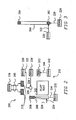
- FIG. 7 shows a block diagram view of a flight system 700, according to an embodiment of the present invention.
- Flight vehicle 702 is a particular embodiment of vehicle 102 shown in Figure 1 , and may include a flight vehicle controller 704 that is a particular embodiment of vehicle controller 120 shown in Figure 2 .
- Flight vehicle controller 704 may include a flight control computer 706, one or more pilot control actuators 708, a secure communication unit 710, an intra vehicle communication unit 712, an external communication unit 714, and/or a sensor unit 716.
- Flight control computer 706 may be located either on-board or off-board vehicle 702 and may be located within flight vehicle 702 separate from flight vehicle controller 704.
- Pilot control actuators 708 are a particular embodiment of pilot control actuators 122 as shown in Figure 1 and may include electromechanical actuators (EMAs) or some other technology configured to respond to electrical/electronic control.
- EMAs electromechanical actuators
- Flight control computer 706, or mission controller 706, may include a processor 720 and/or a processor memory 722 that may include a mission program 724 and/or one or more encryption keys 726 for encrypting and decrypting messages in cooperation with secure communication unit 710.
- a processor 720 and/or a processor memory 722 may include a mission program 724 and/or one or more encryption keys 726 for encrypting and decrypting messages in cooperation with secure communication unit 710.
- some or all communications into and out of flight vehicle controller 704 may be encrypted or authenticated using various cryptographic algorithms.
- Secure communication unit 710 may include a cryptographic processor, a communication firewall, a memory for storing and retrieving cryptographic keys, and/or dedicated cryptographic hardware for use in performing cryptographic functions including the implementation of cryptographic algorithms such as the Data Encryption Standard (DES), the Advanced Encryption Standard (AES), the Secure Hash Algorithm (SHA-1), and the Message Digest (MD-5) Algorithm.
- secure communication unit 710 may be selectively enabled so that only certain commands and information are cryptographically protected.
- secure communication unit 710 may be disabled or eliminated so that no information flow is cryptographically protected.
- sensor unit 716 includes at least one sensor that provides a measurement signal of a property of the aircraft during flight, where the measurement signal is not used by flight control computer 706, but is instead used by flight vehicle controller 704 to affect operation of one or more dual actuators.
- Processor 720 may be a general-purpose computer processor suitably programmed to fetch, decode, and execute computer instructions including mission program 724.
- Processor memory 722 may be any medium for storing and retrieving information including a Random Access Memory (RAM), a Read Only Memory (ROM), a magnetic disc, an optical disc, a content addressable memory, and/or a register file where processor memory 722.
- Processor memory 722 may be removable from flight vehicle controller 704 in order to provide safekeeping of information, to provide convenient transfer to another vehicle controller, and/or reconfiguration of a replacement vehicle controller.
- Mission program 724 may include an implementation of an algorithm designed to operate flight vehicle 702 according to a predetermined plan including pre-programmed instructions and options for handling various contingencies.
- Encryption keys 726 may be used to encrypt and decrypt information sent to or received from external communication unit 714 and/or intra vehicle communication unit 712 through secure communication unit 710.
- Pilot controls 730 may be either a particular embodiment of pilot controls 200 as shown in Figure 2 , or a particular embodiment of pilot controls 500 as shown in Figure 5 .
- pilot controls 730 may correspond to a standard set of pilot controls corresponding to any flight vehicle include a helicopter, airplane, glider, blimp, airship, and/or spacecraft.
- Pilot controls 730 are coupled with corresponding pilot control actuators 708 through a linkage 732 to provide manipulation of pilot controls 730 in order to operate flight vehicle 702.
- Pilot selector 740 is a particular embodiment of pilot selector 130 shown in Figure 1 and provides pilot select information 742 through a communication link 744 to flight vehicle controller 704.
- pilot selector 740 includes a status light indicating whether a pilot 104 or flight vehicle controller 704 is in command of flight vehicle 704.
- pilot selector 740 includes an electromechanical switch that can be toggled into either an enabled position or a disabled position by flight vehicle controller 704 in order to provide tactile feedback to a pilot regarding the status of pilot selector 740.
- Intra vehicle communication unit 712 may communicate with a portable computer 750 located either onboard flight vehicle 702 or located remotely from flight vehicle 702.
- Portable computer 750 may be a ruggedized laptop computer suitable for use in a harsh environment and configured to communicate with flight vehicle controller 704 to upload and/or download information including mission program 724 and/or status information across communication link 752.
- Both communication links (744, 752) may access flight vehicle controller through intra vehicle communication unit 712 where links (744, 752) may include wired, wireless, and/or optical communication paths.
- External communication unit 714 may send status information to and receive command information from a remote vehicle commander 760 across communication link 762 that may include any wireless communication technology including Radio Frequency (RF), microwave, and optical communications.
- the vehicle status information can include the operational status (e.g. health) and/or history of various flight vehicle systems.
- External communication unit 714 may include one or more antennas, receivers, and/or optical detectors that may be use instead of or in addition to any external communication equipment already available on flight vehicle 702. Either intra vehicle communications unit 712 or external communications unit 714 are configured to send command messages to and receive status messages from flight vehicle controller 704.
- Sensor unit 716 may include one or more sensors such as a Global Positioning Satellite (GPS) receiver configured to provide location information, dynamic sensors for detecting acceleration and/or rotation, altimeter for detecting altitude, cabin sensors for air-pressure, oxygen level, and/or temperature, environmental sensors for detecting conditions either inside or outside the aircraft, and/or reconnaissance.
- GPS Global Positioning Satellite
- sensor unit 716 may include a GPS receiver such as manufactured by NovAtel of Calgary, Alberta, Canada. Other sensors may be included and listed sensors may be omitted in some embodiments, so this list is not considered limiting.
- FIG 8 shows a block diagram view of a helicopter vehicle 802, according to an embodiment of the present invention.
- Helicopter vehicle 802 is a particular embodiment of vehicle 702 in Figure 7 , and may include a flight vehicle controller 804, a pilot interface unit 806, a vehicle operation unit 808, a vehicle sensor unit 828, a weapons control unit 840, a visualization and documentation unit 842, a communications unit 844, and/or a portable computer 750.
- Flight vehicle controller 804 is a particular embodiment of vehicle controller 120 in Figure 1 , and may include pilot control actuators 850 that are a particular embodiment of pilot control actuators 708 shown in Figure 6 .
- Pilot control actuators 850 may include a lateral DEMA 852, a longitudinal DEMA 854, a collective DEMA 856, a throttle DEMA 858, a directional series DEMA 860, and/or a trim DEMA 862.
- Lateral DEMA 852, comprising a roll actuator pair, may be configured to provide roll control of helicopter vehicle 802 through roll controlling elements of pilot controls 870.
- longitudinal DEMA 854, Collective DEMA 856, throttle DEMA 858, directional series DEMA, and trim DEMA provide control of associated helicopter pilot controls 870.
- Pilot interface unit 806 is a particular embodiment of pilot interface unit 106 shown in Figure 1 , and may include pilot controls 870 and/or pilot selector 872.
- Pilot selector 872 is a particular embodiment of pilot selector 130 shown in Figure 1 .
- Vehicle operation unit 808 is a particular embodiment of vehicle operation unit 108 in Figure 1 and may include an airspeed sensor, a pressure altimeter, a radar altimeter, a Global Positioning System (GPS), as well as sensors to measure engine speed, torque, transmission operation, and rotor speed. Although specific sensors are described, this is not considered limiting.
- GPS Global Positioning System
- Weapons control unit 840 may provide targeting and launch control over one or more weapon systems associated with helicopter vehicle 802 including air-to-air missiles, Gattling cannon, chaff dispensers, and/or tactical countermeasures.
- Visualization and documentation unit 842 may include one or more cameras, a voice recorder, and/or a data recorder to provide visualization and documentation of a helicopter mission including weapons targeting and deployment information, vehicle navigation, and/or vehicle and/or vehicle controller sensor readings.
- Communications unit 844 may include radios, lights, a vehicle transponder, a microwave modem, and/or an airborne link such as the tactical common data link (TCDL).
- Portable computer 750 may provide mission data for use by a pilot and/or flight crew where the mission data may include a mission program for use in flight vehicle controller 804. Alternatively, portable computer 750 may provide survey and/or environmental information for a pilot and/or passengers.
- Modification of an existing helicopter platform would provide an unmanned helicopter with the same performance as its manned counterpart, where pilot control actuators are tied into the pilot controls of the existing helicopter controls in a parallel fashion so that the pilot control actuators may be quickly be engaged or disengaged.
- a flight control computer in flight vehicle controller 804 may provide commands to the actuators using aircraft state data to determine the appropriate commands to fly the defined mission profiles.
- the quick disconnect feature of the actuators provide an effective safety feature to the manned aircraft and does not increase the control loads in the baseline aircraft control system.
- One exemplary embodiment of the quick disconnect capability may include a belt-drive in combination with an electric or electromechanical clutch.
- FIG. 9 shows a multi-mode unmanned and manned vehicle piloting method flow diagram 900, according to an embodiment of the present invention.
- Flow 900 includes a method of piloting a vehicle including the operations of modifying a vehicle having at least one pilot control to include a vehicle controller and at least one pilot control actuator in operation 902, where the at least one pilot control actuator is operatively coupled with the at least one pilot control. A plurality of pilot controls and pilot control actuators may be used.
- Flow 900 continues with detecting whether the vehicle controller is enabled in operation 904. Detection in this case may be accomplished by vehicle controller 120, where the status of pilot selector 130 is examined as discussed in reference to Figure 1 .
- flow 900 continues with piloting the modified vehicle with the vehicle controller to provide unmanned operation of the modified vehicle in operation 906. Conversely, if the vehicle controller is not enabled, then flow 900 continues with piloting the modified vehicle with a human pilot to provide manned operation of the modified vehicle in operation 908.
- the status of pilot selector 130 may again be assessed where flow 900 returns to operation 904 after a predetermined delay such as a control system sampling period. In this manner, operation of pilot selector 130 to enable and/or disable vehicle controller 120 may be detected and a smooth transition between manned and unmanned operation as well as between unmanned and manned operation effected.
- the pilot select transition time between when the vehicle controller is enabled to provide unmanned operation of the modified vehicle and the vehicle controller is disabled to provide manned operation of the modified vehicle is less than about one second after a selection change is registered.
- This rapid pilot select transition time may also be considered a "quick disconnect" feature where a human pilot may rapidly take command of a modified vehicle previously under the command of the vehicle controller.
- FIG 10 shows an exemplary dual electromechanical actuator (DEMA) 1002 operatively coupled to an interface element (IE) 1004, according to an embodiment of the present invention.
- DEMA 1002 is a particular embodiment of DEMA 220 in Figure 2 , and may include a higher-bandwidth (HB) electromechanical actuator (HB-EMA) 1006 and a lower-bandwidth LB-EMA 1008.
- HB-EMA higher-bandwidth electromechanical actuator
- LB-EMA 1008 a lower-bandwidth EMA
- a higher-bandwidth EMA may have a faster response time to electronic control and/or a quicker movement through a particular range of motion and/or rotation.
- a lower-bandwidth EMA may have a slower response time and/or a slower movement through a particular range of motion and/or rotation.
- a gear ratio of a transmission device may determine the torque and/or response speed as a measure of bandwidth.
- HB-EMA 1006 and LB-EMA 1008 may be operatively coupled to interface element (IE) 1004 in a parallel connection so that both HB-EMA 1006 and LB-EMA 1008 may independently control the same type of motion of IE 1004.
- IE interface element
- Other DEMAs may be used, so this description is not considered limiting.
- HB-EMA 1006 may be coupled through a first linkage 1010 operatively coupled to a first clutch 1012 that selectively couples movement on a first linkage 1010 to a first portion of IE 1004.
- First clutch 1012 may be engaged to couple movement between first linkage 1010 and the first portion of IE 1004 and disengaged to isolate movement of first linkage 1010 and IE 1004.
- LB-EMA 1008 may be coupled through a second linkage 1014 operatively coupled to a second clutch 1016 that selectively couples movement on a second linkage 1014 to a second portion of IE 1004.
- Second clutch 1016 may be engaged to couple movement between second linkage 1014 and the second portion of IE 1004 and disengaged to isolate movement of second linkage 1014 and IE 1004.
- First clutch 1012 and second clutch 1016 may be electrically operated to selectively and independently couple movement on the first and second linkages (1010, 1012) to IE 1004.
- linkage 1010 and linkage 1014 may comprise a parallel linkage 1018 that is a particular embodiment of linkage 222 shown in Figure 3 .
- LB-EMA 1008 may provide movement through an entire range of motion, while HB-EMA 1006 may provide movement through only a portion of the entire range of motion. In this manner, LB-EMA 1008 may have full authority and HB-EMA may have only partial authority. Due to the faster response time of HB-EMA 1006, the authority of movement is restricted to limit potential control instability. Further, the dual actuator configuration provides for redundancy in the case of a component or system failure.
- LB-EMA 1008 defines a full authority of pilot control movement covering the entire range of allowable motion for the particular pilot control.
- the smaller scope of HB-EMA 1006 defines a partial authority for pilot control movement having a first center of travel when HB-EMA 1006 is engaged with the pilot control.
- LB-EMA 1008 may be included as a part of an existing aircraft trim system or supplied separately for a pilot control without an associated trim element. In this and other embodiments, an existing vehicle having entirely manual pilot controls may be modified for unmanned operation while maintaining the ability to pilot the vehicle in a manned vehicle mode.
- DEMA 1002 is a particular embodiment of lateral DEMA 220 while IE 1004 is a particular embodiment of cyclic extension 302, both shown in Figure 3 .
- IE 1004 is connected to a pilot control 1030 that is a particular embodiment of cyclic 204 shown in Figure 3 .
- pilot control 1030 has an axis 1032 extending through a portion of pilot control 1030 that defines motion through a range of lateral and/or rotational movement.
- movement through the larger range 1040 has a first range of motion 1060 and movement through the smaller range 1042 has a second range of motion 1062.
- smaller range 1042 is shown as entirely included within larger range 1040, this is not considered limiting since larger range 1040 and smaller range 1042 may completely overlap, partially overlap, or be non-overlapping. Further, smaller range 1042 may not be centered within larger range 1040, and may instead be defined anywhere in the range of motion defined for IE 1004.
- First clutch 1012 may be engaged with IE 1004 while second clutch 1016 is disengaged from IE 1004, or vice versa.
- second clutch 1016 when second clutch 1016 is engaged LB-EMA 1008 may hold the position of pilot control 1030, while first clutch 1012 is disengaged allowing HB-EMA 1006 to be positioned into a favorable new position prior to re-engagement of first clutch 1012.
- first clutch 1012 when first clutch 1012 is engaged HB-EMA 1006 may hold the position of pilot control 1030, while second clutch 1016 is disengaged allowing LB-EMA 1008 to be positioned into a favorable new position prior to re-engagement of second clutch 1016.
- the EMAs (1006, 1008) may be repositioned relative to each other in order to avoid exceeding an actuator travel limit while operating an associated pilot control.
- the actuator travel limit may include an end-point of movement or a region of movement having a property such as higher/lower torque, and/or response time/speed.
- FIG 11 shows an unmanned operation flow diagram 1100 corresponding to piloting the modified vehicle using the vehicle controller, according to an embodiment of the present invention.
- Flow 1100 may include the operations of determining the current vehicle state and desired vehicle state in operation 1102, comparing the current vehicle state to the desired vehicle state to determine a vehicle state difference in operation 1104, and determining whether to modify the vehicle state in operation 1106. If the differences between the current vehicle state to the desired vehicle state are small (e.g. below a predetermined threshold), then the determination in operation 1106 will be "N" and control will move to operation 1102. Alternatively, if the differences between the current vehicle state and the desired vehicle state are above a predetermined threshold then the determination in operation 1106 will be "Y" and control will move to operation 1108.
- Flow 1100 continues with calculating the change in one or more pilot control positions corresponding to the vehicle state difference in operation 1108, where the change in the pilot control position is required to produce the desired vehicle state change. Once the change in each pilot control position is calculated, flow 1100 continues with calculating the required actuator position change corresponding to the pilot control position change in operation 1110. Once the new actuator position is determined, flow 1100 continues with commanding the new actuator position in operation 1112, and control moves to operation 1102.
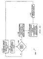
- FIG 12 shows an actuator positioning flow diagram 1200, according to an embodiment of the present invention.
- Positioning flow 1200 corresponds to a particular embodiment of operation 1110 described in reference to Figure 11 .
- Flow 1200 begins in operation 1202 where positioning flow 1200 is invoked to command one or more new pilot control positions, and control moves to operation 1204 which determines whether or not each pilot control commanded to change corresponds to a high control load that requires adjustment. If a particular commanded pilot control is a high control load that requires adjustment, the determination in operation 1204 is "Y" and control moves to operation 1206 where the control load is adjusted using a low bandwidth actuator coupled to the vehicle pilot control.
- the low bandwidth actuator may be included as a part of an existing vehicle trim system.
- the determination is "N” and control moves to operation 1208 where a determination is made regarding whether the commanded position for a particular actuator will exceed the actuator travel limits. If the actuator travel limits will not be exceeded by moving to the newly commanded pilot control position, the determination in operation 1208 is "N” and control moves to operation 1210 where the actuator position is changed as commanded. Once each of the selected pilot control actuators is changed to the commanded position, flow 1200 concludes in operation 1212 with a stop. In operation 1208, if the actuator travel limits will be exceeded by moving to the newly commanded pilot control position, the determination in operation 1208 is "Y" and control moves to operation 1214.
- Flow 1200 continues by disengaging the limit exceeding actuator from the associated operator control in operation 1214, moving the actuator position to a center of travel for the particular actuator in operation 1246, and re-engaging the particular actuator to the pilot control in operation 1218, and control moves to operation 1210.
- an actuator configured to operate a particular pilot control is re-aligned to the center of travel to provide flexibility of actuator movement without exceeding actuator movement limits.
- an electromechanical clutch device may be used to selectively engage and disengage a mechanical coupling between a portion of the particular actuator and the particular pilot control.
- FIG 13 shows an exemplary dual electromechanical actuator (DEMA) 1302 operatively coupled to an interface element (IE) 1304, according to an embodiment of the present invention.
- DEMA 1302 is a particular embodiment of DEMA 208 in Figure 2 , and may include a higher-bandwidth (HB) electromechanical actuator (HB-EMA) 1306 and a lower-bandwidth LB-EMA 1308.
- HB-EMA 1306 and LB-EMA 1308 may be operatively coupled to interface element (IE) 1304 in a series connection so that both HB-EMA 1306 and LB-EMA 1308 may cooperatively control the same type of motion of IE 1304.
- Other DEMAs may be used, so this description is not considered limiting.
- HB-EMA 1306 may be coupled through a first linkage 1310 operatively coupled to a first clutch 1312 that selectively couples movement on a first linkage 1310 to a first portion of IE 1304.
- LB-EMA 1308 may be coupled through a second linkage 1314 operatively coupled to a second clutch 1316 that selectively couples movement on a second linkage 1314 to a second portion of IE 1304.
- First linkage 1310 and second linkage 1314 may each be a drive belt for coupling the rotational movement of a portion of First clutch 1312 and second clutch 1316 may be electrically operated to selectively and cooperatively couple movement on the first and second linkages (1310, 1312) to IE 1304.
- linkage 1310 and linkage 1314 may comprise a linkage 1318 that is a particular embodiment of linkage 234 shown in Figure 2 .
- Figure 14 shows an end view of first clutch 1312, second clutch 1316, and interface element 1314, according to an embodiment of the present invention.
- First clutch 1312 is configured to impart back and forth rotational movement about a long axis of IE 1304 in a smaller range of motion 1402 between a first limit 1404 and a second limit 1406.
- second clutch 1316 is configured to impart back and forth rotational movement about the long axis of IE 1304 in a larger range of motion 1420 between a first limit 1422 and a second limit 1424.
- first clutch 1312 may be disengaged from IE 1304, move to a new position at or near an expected center of travel 1430, and then re-engaged with IE 1304 as described in reference to Figure 12 .
- second clutch 1316 maintains the position of IE 1304, the range of motion 1402 may be centered about center of travel 1430 allowing first EMA 1306 to provide a full-range of expected motion at a higher bandwidth.
- first clutch 1312 may be engaged while second clutch 1316 is disengaged in order to provide positive control of IE 1304 at all times. In this manner, either clutch may be alternately engaged or disengaged to re-adjust a center point of operation.
- smaller range 1402 is shown as entirely included within larger range 1420, this is not considered limiting since larger range 1420 and smaller range 1402 may completely overlap, partially overlap, or be non-overlapping. Further, smaller range 1402 may not be centered within larger range 1420, and may instead be defined anywhere in the range of motion defined for IE 1304.
- second EMA 1308 is not moving and second clutch 1316 is engaged to maintain IE 1304 in a stationary position while first clutch 1312 is re-adjusted.
- first EMA 1306 is not moving and first clutch is engaged to maintain IE 1304 in a stationary position while second clutch 1316 is re-adjusted.
- either EMA/clutch pair may independently control the operation of IE 1304 to provide for readjustment of the other EMA/clutch pair and to compensate for system failures where either EMA/clutch pair or the related control hardware and/or software may not be functioning properly.
- second EMA 1308 is moving according to the commands of a vehicle control loop.
- first EMA 1306 is moved in harmony with the movement of second EMA 1308 to provide a smooth clutching and de-clutching action whether IE 1304 is stationary or moving at the time of rea-adjustment.
- rotational motion is described in reference to rotational motion limits, EMAs (1306, 1308) may be used to provide linear movement in reference to linear motion limits.
- the type of EMA and/or movements are not considered limiting.
- One or more embodiments of the present invention provide various benefits including lower unmanned vehicle development and deployment costs while providing enhanced multi-mode unmanned and manned vehicle capabilities.
- Embodiments described above illustrate but do not limit the invention. It should also be understood that numerous modifications and variations are possible in accordance with the principles of the present invention. Accordingly, the scope of the invention is defined only by the following claims.
Landscapes
- Engineering & Computer Science (AREA)
- Aviation & Aerospace Engineering (AREA)
- Automation & Control Theory (AREA)
- Mechanical Engineering (AREA)
- Remote Sensing (AREA)
- Radar, Positioning & Navigation (AREA)
- Physics & Mathematics (AREA)
- General Physics & Mathematics (AREA)
- General Engineering & Computer Science (AREA)
- Control Of Position, Course, Altitude, Or Attitude Of Moving Bodies (AREA)
- Regulating Braking Force (AREA)
- Transmission Devices (AREA)
- Body Structure For Vehicles (AREA)
Claims (19)
- Verfahren zum Pilotieren eines Luftfahrzeugs (102, 402, 702, 802), wobei das Verfahren umfasst:Modifizieren (902) eines Luftfahrzeugs, das zumindest ein zur Betätigung durch einen Piloten (104) zwecks bemannten Betriebs ausgebildetes Pilotensteuerungselement (110, 200) aufweist, in einer Weise, dass es einen Fahrzeugcontroller (120, 704, 804) und zumindest einen ersten Pilotensteuerungselementaktor (1006, 1306) und einen zweiten Pilotensteuerungselementaktor (1008, 1308) beinhaltet, die eine duale Aktoranordnung (1002, 1302) bilden, wobei die zumindest zwei Pilotensteuerungselementaktoren mit dem zumindest einen Pilotensteuerungselement wirkgekoppelt sind, wobei die Bandbreite zulässiger Bewegung des ersten Aktors größer ist als die Bandbreite zulässiger Bewegung des zweiten Aktors, um ein verbessertes Bandbreitenpotenzial bereitzustellen;Detektieren (904), ob der Fahrzeugcontroller aktiviert ist;Wahrnehmen (144) zumindest einer Luftfahrzeugeigenschaft;Berechnen (1100) einer Fahrzeugcontrollerreaktion auf Grundlage der wahrgenommenen Eigenschaft; undPilotieren des modifizierten Luftfahrzeugs mittels des Fahrzeugcontrollers durch Betätigen der zumindest zwei Pilotensteuerungselementaktoren in Übereinstimmung mit der Fahrzeugcontrollerreaktion, wenn der Fahrzeugcontroller aktiviert ist (906).
- Verfahren nach Anspruch 1, das weiterhin umfasst:Pilotieren des modifizierten Fahrzeugs mittels eines menschlichen Piloten, wenn der Fahrzeugcontroller nicht aktiviert ist (908).
- Verfahren nach Anspruch 1 oder 2, wobei eine Pilotenauswahlübergangszeit zwischen dem Aktiviertsein des Fahrzeugcontrollers, um einen unbemannten Betrieb des modifizierten Fahrzeugs bereitzustellen, und dem Inaktiviertsein des Fahrzeugcontrollers, um einen bemannten Betrieb des modifizierten Fahrzeugs bereitzustellen, kürzer als etwa eine Sekunde ist.
- Verfahren nach einem der vorstehenden Ansprüche, wobei der Vorgang des Berechnens einer Fahrzeugcontrollerreaktion auf Grundlage der wahrgenommenen Eigenschaft weiterhin umfasst:Vergleichen eines aktuellen Fahrzeugzustands (1102) mit einem gewünschten Fahrzeugzustand (1104), um einen Fahrzeugzustandsunterschied zu bestimmen;Berechnen der Veränderung einer oder mehrerer Pilotensteuerungselementpositionen auf Grundlage des Fahrzeugzustandsunterschieds (1108);Berechnen der Veränderung einer oder mehrerer Aktorpositionen in Entsprechung zur berechneten Veränderung einer oder mehrerer Pilotensteuerungselementpositionen (1110), undBefehlen der berechneten Veränderung der einen oder mehreren Aktorpositionen (1112).
- Verfahren nach einem der vorstehenden Ansprüche, wobei der Vorgang des Pilotierens des modifizierten Luftfahrzeugs mittels des Fahrzeugcontrollers durch Betätigen der zumindest zwei Pilotensteuerungselementaktoren, wenn die angeordnete Veränderung der Aktorposition eine Aktorweggrenze (1208) überschreitet, weiterhin umfasst:Lösen des Aktors vom Pilotensteuerungselement (1214);Positionieren des Aktors an einer Wegmitte (1216); undWiederverbinden des Aktors mit dem Pilotensteuerungselement (1218).
- Verfahren nach einem der vorstehenden Ansprüche, wobei einer vom ersten Pilotensteuerungselementaktor und zweiten Pilotensteuerungselementaktor im nicht modifizierten Luftfahrzeug enthalten ist.
- Vorrichtung zum Umwandeln eines bemannten Luftfahrzeugs (102, 402, 702, 802) für den unbemannten Flug, wobei das Luftfahrzeug zumindest ein Pilotensteuerungselement beinhaltet, das gehandhabt werden kann, um den Betrieb des Luftfahrzeugs zu beeinflussen, wobei die Vorrichtung umfasst:einen ersten Aktor (1006, 1306), der ausgebildet ist, um wahlweise zumindest eines von Bewegung und Widerstand gegen Bewegung in einer ersten Weise, einschließlich zumindest entweder einer Linear- oder Rotationsbewegung, bereitzustellen, und der einen ersten Bereich aufweist, der ein erstes Maß an zulässiger Bewegung beschreibt;eine erste Kupplung (1012, 1312), die ausgebildet ist, um Bewegung des ersten Aktors wahlweise ans Pilotensteuerungselement zu koppeln;einen zweiten Aktor (1008, 1308), der ausgebildet ist, um wahlweise zumindest eines von Bewegung und Widerstand gegen Bewegung in der ersten Weise bereitzustellen, und der einen ein zweites Maß an zulässiger Bewegung beschreibenden zweiten Bereich aufweist, der größer als der erste Bereich ist;eine zweite Kupplung, die ans Pilotensteuerungselement wirkgekoppelt ist und ausgebildet ist, um Bewegung des zweiten Aktors wahlweise ans Pilotensteuerungselement zu koppeln; undeinen Fahrzeugcontroller (120, 704, 804), der ausgebildet ist, um den ersten Aktor, die erste Kupplung, den zweiten Aktor und die zweite Kupplung zu betätigen, um das Pilotensteuerungselement wahlweise zu beeinflussen, wobei der Fahrzeugcontroller wahlweise aktiviert werden kann, damit er die Pilotensteuerungselementaktoren und Kupplungen betätigt, um einen unbemannten Betrieb des Luftfahrzeugs bereitzustellen, und deaktiviert werden kann, um einen bemannten Betrieb des Luftfahrzeugs bereitzustellen.
- Vorrichtung nach Anspruch 7,
wobei das Luftfahrzeug entweder ein Hubschrauber oder ein Flugzeug oder ein Raumfahrzeug ist; und
wobei der Fahrzeugcontroller ausgebildet ist, um Gier-, Nick-, Roll- und Schubsteuerung des Luftfahrzeugs bereitzustellen. - Vorrichtung nach Anspruch 7 oder 8, wobei der Fahrzeugcontroller ausgebildet ist, um Befehlsinformationen von zumindest entweder einem Computer im Luftfahrzeug oder einem entfernten Bediener (150, 760) zu empfangen, der vom Luftfahrzeug getrennt ist.
- Vorrichtung nach einem der Ansprüche 7 - 9, wobei das Luftfahrzeug einen Flugsteuerungsrechner (706) umfasst und die Vorrichtung weiterhin zumindest einen Sensor umfasst, um ein Messsignal von einer Eigenschaft des Luftfahrzeugs während des Flugs bereitzustellen, wobei das Signal vom Flugsteuerungsrechner nicht verwendet wird und vom Fahrzeugcontroller verwendet wird, um den Betrieb des zumindest einen Aktors zu beeinflussen.
- Vorrichtung nach einem der Ansprüche 7 - 10, die weiterhin umfasst:ein erstes Schnittstellenelement (1010, 1310), das ausgebildet ist, um Bewegung vom ersten Aktor zur ersten Kupplung zu übermitteln; undein zweites Schnittstellenelement (1014, 1314), das ausgebildet ist, um Bewegung vom zweiten Aktor zur zweiten Kupplung zu übermitteln, wobei jedes Schnittstellenelement zumindest eines von einer Druckstange, einem Hebel, einem Zahnrad, einer Rolle bzw. einem Rad und einem Band beinhaltet,wobei der erste Aktor einen elektromechanischen Aktor mit höherer Bandbreite (HB-EMA) umfasst und der zweite Aktor einen elektromechanischen Aktor mit niedrigerer Bandbreite (LB-EMA) umfasst, wobei der HB-EMA zumindest entweder eine schnellere Reaktionszeit auf Betätigung durch den Fahrzeugcontroller oder eine schnellere Bewegung durch einen bestimmten Bewegungsbereich aufweist.
- Vorrichtung nach Anspruch 11, wobei der LB-EMA und der HB-EMA in Serie wirkgekoppelt sind.
- Vorrichtung nach Anspruch 11, wobei der kleinere Bereich des HB-EMA ein teilweises Zulassen von Pilotensteuerungselementbewegung mit einer ersten Wegmitte festlegt, wenn der HB-EMA mit dem Pilotensteuerungselement verbunden ist, wobei der HB-EMA zur Neuanpassung an eine zweite Wegmitte in der Lage ist, die sich von der ersten Wegmitte unterscheidet, wenn der HB-EMA vom Pilotensteuerungselement gelöst ist.
- Vorrichtung nach einem der Ansprüche 7 - 13, wobei der Fahrzeugcontroller weiterhin umfasst:einen Flugsteuerungsrechner, der konfiguriert ist zum Ausführen eines Einsatzprogramms zur Betätigung der Pilotensteuerungselementaktoren und der Kupplungen, um das Luftfahrzeug gemäß dem Einsatzprogramm zu pilotieren.
- Vorrichtung nach einem der Ansprüche 7 - 14, wobei die Aktoren in paralleler Weise mit den Pilotensteuerungselementen ausgefahren werden.
- Vorrichtung nach einem der Ansprüche 7 - 15, wobei jeder Aktor eine Schnelltrennfähigkeit beinhaltet, um einen raschen Übergang des Luftfahrzeugsbefehls auf einen menschlichen Piloten bereitzustellen.
- Vorrichtung nach einem der Ansprüche 7 - 16, die weiterhin zumindest einen Sensor umfasst, der ausgebildet ist, um zumindest eine Luftfahrzeugseigenschaft zu messen und dem Fahrzeugcontroller ein Messsignal bereitzustellen, wobei der Betrieb des Luftfahrzeugs durch den Fahrzeugcontroller vom Messsignal beeinflusst wird.
- Vorrichtung nach einem der Ansprüche 7 - 17, wobei einer vom ersten Aktor und zweiten Aktor im nicht umgewandelten Luftfahrzeug enthalten ist.
- Hubschrauber (402, 802), der eine Vorrichtung zum Umwandeln eines bemannten Luftfahrzeugs für den unbemannten Flug nach einem der Ansprüche 7 - 18 umfasst.
Applications Claiming Priority (2)
| Application Number | Priority Date | Filing Date | Title |
|---|---|---|---|
| US11/388,026 US7624943B2 (en) | 2006-03-22 | 2006-03-22 | Multi-mode unmanned and manned vehicle systems and methods |
| PCT/US2007/005940 WO2008054470A2 (en) | 2006-03-22 | 2007-03-07 | Multi-mode unmanned and manned vehicle systems and methods |
Publications (2)
| Publication Number | Publication Date |
|---|---|
| EP1996459A2 EP1996459A2 (de) | 2008-12-03 |
| EP1996459B1 true EP1996459B1 (de) | 2010-09-15 |
Family
ID=38532334
Family Applications (1)
| Application Number | Title | Priority Date | Filing Date |
|---|---|---|---|
| EP07867011A Not-in-force EP1996459B1 (de) | 2006-03-22 | 2007-03-07 | Multimodale bemannte und unbemannte fahrzeugsysteme und -verfahren |
Country Status (6)
| Country | Link |
|---|---|
| US (3) | US7624943B2 (de) |
| EP (1) | EP1996459B1 (de) |
| JP (1) | JP5225263B2 (de) |
| AT (1) | ATE481317T1 (de) |
| DE (1) | DE602007009203D1 (de) |
| WO (1) | WO2008054470A2 (de) |
Cited By (3)
| Publication number | Priority date | Publication date | Assignee | Title |
|---|---|---|---|---|
| WO2013169320A3 (en) * | 2012-02-10 | 2014-02-13 | Merlin Technology, Inc. | Autopilot and methods |
| US9150308B2 (en) | 2012-02-10 | 2015-10-06 | Merlin Technology, Inc. | Rotorcraft autopilot system, components and methods |
| US10730609B2 (en) | 2016-03-03 | 2020-08-04 | Sikorsky Aircraft Corporation | Fly-by-wire retrofit kit |
Families Citing this family (63)
| Publication number | Priority date | Publication date | Assignee | Title |
|---|---|---|---|---|
| US8944822B2 (en) * | 2005-07-22 | 2015-02-03 | Appareo Systems, Llc | Synchronized video and synthetic visualization system and method |
| US7624943B2 (en) | 2006-03-22 | 2009-12-01 | The Boeing Company | Multi-mode unmanned and manned vehicle systems and methods |
| US7581702B2 (en) | 2006-06-09 | 2009-09-01 | Insitu, Inc. | Wirelessly controlling unmanned aircraft and accessing associated surveillance data |
| US9202318B2 (en) | 2006-09-25 | 2015-12-01 | Appareo Systems, Llc | Ground fleet operations quality management system |
| US9047717B2 (en) | 2006-09-25 | 2015-06-02 | Appareo Systems, Llc | Fleet operations quality management system and automatic multi-generational data caching and recovery |
| US9172481B2 (en) | 2012-07-20 | 2015-10-27 | Appareo Systems, Llc | Automatic multi-generational data caching and recovery |
| US8014906B2 (en) * | 2006-12-19 | 2011-09-06 | The Boeing Company | Multi-axis trim processing |
| FR2910437B1 (fr) * | 2006-12-22 | 2009-03-06 | Thales Sa | Procede et dispositif d'aide au retablissement d'un controle de vehicule en mouvement par un operateur du vehicule. |
| US7686680B2 (en) * | 2007-06-26 | 2010-03-30 | Honeywell International Inc. | Closed-loop cabin pressure control system test method with actual pressure feedback |
| SI2500261T1 (sl) * | 2007-08-09 | 2017-09-29 | Lta Corporation | Lečasto zračno plovilo in povezane kontrole |
| US8527118B2 (en) * | 2007-10-17 | 2013-09-03 | The Boeing Company | Automated safe flight vehicle |
| US8255098B2 (en) * | 2007-10-17 | 2012-08-28 | The Boeing Company | Variably manned aircraft |
| US7970583B2 (en) * | 2007-12-28 | 2011-06-28 | United Technologies Corporation | Degraded actuator detection |
| FR2946017B1 (fr) * | 2009-05-29 | 2012-09-28 | Airbus France | Systeme pour la commande d'au moins un moteur d'aeronef et aeronef comportant un tel systeme de commande. |
| FR2946016B1 (fr) * | 2009-05-29 | 2012-09-28 | Airbus France | Systeme pour la commande d'au moins un moteur d'aeronef et aeronef comportant un tel systeme de commande. |
| JP2013512147A (ja) * | 2009-11-25 | 2013-04-11 | エアロバイロメント,インコーポレイテッド | デバイスの自動構成制御 |
| CA2824932C (en) | 2011-01-14 | 2016-03-22 | Bell Helicopter Textron Inc. | Flight control laws for vertical flight path control |
| US8918230B2 (en) * | 2011-01-21 | 2014-12-23 | Mitre Corporation | Teleoperation of unmanned ground vehicle |
| US20120239200A1 (en) * | 2011-02-28 | 2012-09-20 | D-Box Technologies Inc. | Remote object vibro-kinetic feedback system and method |
| US9547929B1 (en) | 2011-04-25 | 2017-01-17 | Honeywell International Inc. | User interface device for adaptive systems |
| ITTO20110681A1 (it) * | 2011-07-27 | 2013-01-28 | Csp Innovazione Nelle Ict Scarl | Metodo per consentire missioni di veicoli aerei senza pilota, in particolare in spazi aerei non segregati |
| CN102968059B (zh) * | 2012-08-10 | 2016-07-13 | 中国商用飞机有限责任公司 | 飞机起落架模拟器 |
| US8930044B1 (en) | 2012-12-28 | 2015-01-06 | Google Inc. | Multi-part navigation process by an unmanned aerial vehicle for navigating to a medical situatiion |
| US9051043B1 (en) * | 2012-12-28 | 2015-06-09 | Google Inc. | Providing emergency medical services using unmanned aerial vehicles |
| US9102406B2 (en) | 2013-02-15 | 2015-08-11 | Disney Enterprises, Inc. | Controlling unmanned aerial vehicles as a flock to synchronize flight in aerial displays |
| US9283046B2 (en) * | 2013-03-15 | 2016-03-15 | Hansen Medical, Inc. | User interface for active drive apparatus with finite range of motion |
| US10849702B2 (en) | 2013-03-15 | 2020-12-01 | Auris Health, Inc. | User input devices for controlling manipulation of guidewires and catheters |
| US9342074B2 (en) * | 2013-04-05 | 2016-05-17 | Google Inc. | Systems and methods for transitioning control of an autonomous vehicle to a driver |
| RU2533005C1 (ru) * | 2013-08-27 | 2014-11-20 | Александр Анатольевич Маковский | Способ обеспечения доставки донорской крови и (или) ее компонентов с применением беспилотного летательного аппарата |
| US9284996B2 (en) | 2013-10-23 | 2016-03-15 | Sikorsky Aircraft Corporation | Selective electrical control of electromechanical clutch assembly |
| CN103914077A (zh) * | 2014-04-03 | 2014-07-09 | 江西洪都航空工业集团有限责任公司 | 一种有人/无人可选择双模飞行控制系统 |
| US9651944B2 (en) | 2015-03-22 | 2017-05-16 | Microsoft Technology Licensing, Llc | Unmanned aerial vehicle piloting authorization |
| JP6304086B2 (ja) * | 2015-03-23 | 2018-04-04 | トヨタ自動車株式会社 | 自動運転装置 |
| US10266250B2 (en) * | 2015-06-12 | 2019-04-23 | Bell Helicopter Textron Inc. | Control inceptor management system |
| JP2017001597A (ja) | 2015-06-15 | 2017-01-05 | トヨタ自動車株式会社 | 自動運転装置 |
| US9922282B2 (en) * | 2015-07-21 | 2018-03-20 | Limitless Computing, Inc. | Automated readiness evaluation system (ARES) for use with an unmanned aircraft system (UAS) |
| CN105867211A (zh) * | 2016-03-16 | 2016-08-17 | 安徽钰龙信息科技有限公司 | 一种穿戴式无人机无线电频谱感知装置 |
| US10752339B2 (en) * | 2016-03-18 | 2020-08-25 | The Boeing Company | Customizing aircraft performance systems and methods |
| US10359779B2 (en) | 2016-03-22 | 2019-07-23 | Aurora Flight Sciences Corporation | Aircrew automation system and method |
| JP7031581B2 (ja) * | 2016-06-02 | 2022-03-08 | ソニーグループ株式会社 | 情報処理装置と情報処理方法 |
| JP6778872B2 (ja) | 2016-06-28 | 2020-11-04 | パナソニックIpマネジメント株式会社 | 運転支援装置及び運転支援方法 |
| US10577082B2 (en) | 2016-08-12 | 2020-03-03 | Sikorsky Aircraft Corporation | Cockpit control of a fixed wing aircraft |
| US10816970B2 (en) | 2017-06-15 | 2020-10-27 | Aurora Flight Sciences Corporation | System and method for performing an emergency descent and landing |
| US10453351B2 (en) | 2017-07-17 | 2019-10-22 | Aurora Flight Sciences Corporation | System and method for detecting obstacles in aerial systems |
| US10509415B2 (en) | 2017-07-27 | 2019-12-17 | Aurora Flight Sciences Corporation | Aircrew automation system and method with integrated imaging and force sensing modalities |
| KR101999186B1 (ko) | 2017-09-25 | 2019-07-11 | 주식회사 대한항공 | 소형 유인헬기의 무인화 조종계통 및 그 개조방법 |
| US11215984B2 (en) * | 2018-01-09 | 2022-01-04 | Uatc, Llc | Systems and methods for controlling an autonomous vehicle |
| US10850397B2 (en) | 2018-04-19 | 2020-12-01 | Aurora Flight Sciences Corporation | System and method for providing in-cockpit actuation of aircraft controls |
| US10875662B2 (en) | 2018-04-19 | 2020-12-29 | Aurora Flight Sciences Corporation | Method of robot manipulation in a vibration environment |
| US11005662B2 (en) * | 2018-08-21 | 2021-05-11 | Ut-Battelle, Llc | Multimodal communication system |
| US11037453B2 (en) | 2018-10-12 | 2021-06-15 | Aurora Flight Sciences Corporation | Adaptive sense and avoid system |
| US11151810B2 (en) | 2018-10-12 | 2021-10-19 | Aurora Flight Sciences Corporation | Adaptable vehicle monitoring system |
| US11586196B2 (en) | 2020-01-22 | 2023-02-21 | Honeywell International Inc. | Approach mode activation monitoring function and automatic activation in an event of pilot incapacitation |
| JP7503964B2 (ja) * | 2020-08-21 | 2024-06-21 | 株式会社フジタ | 航空機の遠隔操縦システム |
| US12049301B2 (en) | 2020-12-17 | 2024-07-30 | The Boeing Company | Systems and methods for overriding autonomous control of a device |
| US12077282B2 (en) * | 2021-05-27 | 2024-09-03 | United States Government As Represented By The Secretary Of The Army | Autonomous guidance and flight control system implementation on a partial-authority aircraft |
| US12248313B2 (en) | 2021-07-08 | 2025-03-11 | Valmont Industries, Inc. | System, method and apparatus for providing specialized controller to remotely pilot an unmanned vehicle |
| US11787527B2 (en) | 2021-10-26 | 2023-10-17 | Lockheed Martin Corporation | Actuation system for cockpit control levers |
| JP2025016414A (ja) * | 2021-11-05 | 2025-02-04 | 株式会社A.L.I.Technologies | 有人飛行体用制御システム、端末及びプログラム |
| CN114301590B (zh) * | 2021-12-28 | 2023-11-10 | 西安电子科技大学 | 基于tpm的无人机机载控制系统的可信启动方法及系统 |
| GB2626013A (en) | 2023-01-05 | 2024-07-10 | Airbus Operations Ltd | Control device and method for an aircraft |
| DE102023104855A1 (de) | 2023-02-28 | 2024-08-29 | Liebherr-Aerospace Lindenberg Gmbh | Verfahren zur Regelung eines elektrischen Aktuators eines Luftfahrzeugs |
| US20250198368A1 (en) * | 2023-06-22 | 2025-06-19 | Heathe W. Ball | Liquid-propellant engine and method of use |
Family Cites Families (13)
| Publication number | Priority date | Publication date | Assignee | Title |
|---|---|---|---|---|
| US2620683A (en) * | 1951-09-21 | 1952-12-09 | Gen Motors Corp | Actuator with dual drive |
| US2852212A (en) * | 1955-04-11 | 1958-09-16 | Gen Electric | Automatic and manual control apparatus for aircraft |
| US3421719A (en) * | 1967-09-11 | 1969-01-14 | United Aircraft Corp | Lightweight automatic flight control mechanism |
| CA1050633A (en) * | 1974-12-19 | 1979-03-13 | Ronald J. Miller | Semi-automatic flight control system utilizing limited authority stabilization system |
| US4834319A (en) * | 1987-10-05 | 1989-05-30 | Allied-Signal Inc. | Differentially coupled dual channel actuator |
| US5001646A (en) | 1988-12-19 | 1991-03-19 | Mcdonnell Douglas Corporation | Automated helicopter flight control system |
| US5240207A (en) * | 1992-08-03 | 1993-08-31 | The United States Of America As Represented By The Secretary Of The Navy | Generic drone control system |
| FR2706153B1 (fr) * | 1993-06-07 | 1995-08-18 | Sextant Avionique | Dispositif de pilotage automatique pour aérodynes. |
| JPH08295294A (ja) | 1995-04-26 | 1996-11-12 | Mitsubishi Heavy Ind Ltd | 無人航空機の操縦装置 |
| US5797564A (en) | 1995-05-15 | 1998-08-25 | The Boeing Company | System for backdrive of flight deck controls during autopilot operation |
| US6421719B1 (en) * | 1995-05-25 | 2002-07-16 | Aprisma Management Technologies, Inc. | Method and apparatus for reactive and deliberative configuration management |
| US5806806A (en) * | 1996-03-04 | 1998-09-15 | Mcdonnell Douglas Corporation | Flight control mechanical backup system |
| US7624943B2 (en) | 2006-03-22 | 2009-12-01 | The Boeing Company | Multi-mode unmanned and manned vehicle systems and methods |
-
2006
- 2006-03-22 US US11/388,026 patent/US7624943B2/en active Active
-
2007
- 2007-03-07 JP JP2009501441A patent/JP5225263B2/ja not_active Expired - Fee Related
- 2007-03-07 AT AT07867011T patent/ATE481317T1/de not_active IP Right Cessation
- 2007-03-07 EP EP07867011A patent/EP1996459B1/de not_active Not-in-force
- 2007-03-07 WO PCT/US2007/005940 patent/WO2008054470A2/en not_active Ceased
- 2007-03-07 DE DE602007009203T patent/DE602007009203D1/de active Active
-
2008
- 2008-06-06 US US12/135,055 patent/US7784741B2/en not_active Expired - Fee Related
-
2010
- 2010-07-23 US US12/842,916 patent/US8052096B2/en not_active Expired - Fee Related
Cited By (12)
| Publication number | Priority date | Publication date | Assignee | Title |
|---|---|---|---|---|
| WO2013169320A3 (en) * | 2012-02-10 | 2014-02-13 | Merlin Technology, Inc. | Autopilot and methods |
| US9150308B2 (en) | 2012-02-10 | 2015-10-06 | Merlin Technology, Inc. | Rotorcraft autopilot system, components and methods |
| US9272780B2 (en) | 2012-02-10 | 2016-03-01 | Merlin Technology, Inc. | Rotorcraft autopilot and methods |
| US9586681B2 (en) | 2012-02-10 | 2017-03-07 | Merlin Technology, Inc. | Rotorcraft autopilot system, components and methods |
| US9758244B2 (en) | 2012-02-10 | 2017-09-12 | Merlin Technology, Inc. | Rotorcraft autopilot and methods |
| US10059441B2 (en) | 2012-02-10 | 2018-08-28 | Merlin Technology, Inc. | Rotorcraft autopilot system, components and methods |
| US10351231B2 (en) | 2012-02-10 | 2019-07-16 | Merlin Technology, Inc. | Rotorcraft autopilot and methods |
| US10464662B2 (en) | 2012-02-10 | 2019-11-05 | Merlin Technology, Inc. | Rotorcraft autopilot system, components and methods |
| US10843796B2 (en) | 2012-02-10 | 2020-11-24 | Merlin Technology, Inc. | Rotorcraft advanced autopilot control arrangement and methods |
| US10926872B2 (en) | 2012-02-10 | 2021-02-23 | Merlin Technology, Inc. | Rotorcraft autopilot and methods |
| US11591078B2 (en) | 2012-02-10 | 2023-02-28 | Merlin Technology, Inc. | Rotorcraft autopilot and methods |
| US10730609B2 (en) | 2016-03-03 | 2020-08-04 | Sikorsky Aircraft Corporation | Fly-by-wire retrofit kit |
Also Published As
| Publication number | Publication date |
|---|---|
| US8052096B2 (en) | 2011-11-08 |
| US20070221782A1 (en) | 2007-09-27 |
| DE602007009203D1 (de) | 2010-10-28 |
| US7624943B2 (en) | 2009-12-01 |
| JP5225263B2 (ja) | 2013-07-03 |
| JP2009530185A (ja) | 2009-08-27 |
| US20100286847A1 (en) | 2010-11-11 |
| US20090045296A1 (en) | 2009-02-19 |
| US7784741B2 (en) | 2010-08-31 |
| WO2008054470A3 (en) | 2008-08-07 |
| ATE481317T1 (de) | 2010-10-15 |
| WO2008054470A2 (en) | 2008-05-08 |
| EP1996459A2 (de) | 2008-12-03 |
Similar Documents
| Publication | Publication Date | Title |
|---|---|---|
| EP1996459B1 (de) | Multimodale bemannte und unbemannte fahrzeugsysteme und -verfahren | |
| JP7275272B2 (ja) | 航空機制御システム及び方法 | |
| US20190241252A1 (en) | Control inceptor management system | |
| EP2427374B1 (de) | Luftgestütztes robotersystem | |
| US8255098B2 (en) | Variably manned aircraft | |
| US8370003B2 (en) | System and method for multiple aircraft lifting a common payload | |
| EP3370129B1 (de) | Drehflüglersteuermodusübergangsglättung | |
| EP3620373B1 (de) | Verklemmten detent-monitore für kollektive und zyklische sticks | |
| US20070032923A1 (en) | Heading reference command and control algorithm systems and methods for aircraft turn-to-target maneuvers | |
| EP3379365A1 (de) | System und verfahren zur drehflüglersteuerung | |
| EP3357809A1 (de) | Systeme und verfahren zur stabilisierung von längsbeschleunigung eines drehflüglers | |
| EP3198349B1 (de) | Haptische rückmeldung für echtzeitflugbahnbeschränkungen | |
| EP3613671B1 (de) | Glättung einer drehflüglersteuerungsübergang | |
| CN109515708B (zh) | 用于尾旋翼裕度识别的系统和方法 | |
| EP3492373B1 (de) | System und verfahren zur flugmodusanzeige | |
| US12077282B2 (en) | Autonomous guidance and flight control system implementation on a partial-authority aircraft | |
| US20170291690A1 (en) | High trim demand relieft | |
| US10216187B2 (en) | Unmanned vehicle operating modes | |
| US20230229173A1 (en) | Automatic low-speed aircraft maneuver wind compensation | |
| Rocchio et al. | Flight testing avionics of an optionally piloted aircraft for UAS integration in the civil airspace | |
| WO2025043028A2 (en) | Ground handling of a craft using inceptors | |
| GB2516008A (en) | Inceptor and method for operating an inceptor |
Legal Events
| Date | Code | Title | Description |
|---|---|---|---|
| PUAI | Public reference made under article 153(3) epc to a published international application that has entered the european phase |
Free format text: ORIGINAL CODE: 0009012 |
|
| 17P | Request for examination filed |
Effective date: 20080722 |
|
| AK | Designated contracting states |
Kind code of ref document: A2 Designated state(s): AT BE BG CH CY CZ DE DK EE ES FI FR GB GR HU IE IS IT LI LT LU LV MC MT NL PL PT RO SE SI SK TR |
|
| AX | Request for extension of the european patent |
Extension state: AL BA HR MK RS |
|
| 17Q | First examination report despatched |
Effective date: 20090217 |
|
| GRAP | Despatch of communication of intention to grant a patent |
Free format text: ORIGINAL CODE: EPIDOSNIGR1 |
|
| DAX | Request for extension of the european patent (deleted) | ||
| GRAS | Grant fee paid |
Free format text: ORIGINAL CODE: EPIDOSNIGR3 |
|
| GRAA | (expected) grant |
Free format text: ORIGINAL CODE: 0009210 |
|
| AK | Designated contracting states |
Kind code of ref document: B1 Designated state(s): AT BE BG CH CY CZ DE DK EE ES FI FR GB GR HU IE IS IT LI LT LU LV MC MT NL PL PT RO SE SI SK TR |
|
| REG | Reference to a national code |
Ref country code: GB Ref legal event code: FG4D Ref country code: CH Ref legal event code: EP |
|
| REG | Reference to a national code |
Ref country code: IE Ref legal event code: FG4D |
|
| REF | Corresponds to: |
Ref document number: 602007009203 Country of ref document: DE Date of ref document: 20101028 Kind code of ref document: P |
|
| REG | Reference to a national code |
Ref country code: NL Ref legal event code: VDEP Effective date: 20100915 |
|
| PG25 | Lapsed in a contracting state [announced via postgrant information from national office to epo] |
Ref country code: AT Free format text: LAPSE BECAUSE OF FAILURE TO SUBMIT A TRANSLATION OF THE DESCRIPTION OR TO PAY THE FEE WITHIN THE PRESCRIBED TIME-LIMIT Effective date: 20100915 Ref country code: LT Free format text: LAPSE BECAUSE OF FAILURE TO SUBMIT A TRANSLATION OF THE DESCRIPTION OR TO PAY THE FEE WITHIN THE PRESCRIBED TIME-LIMIT Effective date: 20100915 Ref country code: FI Free format text: LAPSE BECAUSE OF FAILURE TO SUBMIT A TRANSLATION OF THE DESCRIPTION OR TO PAY THE FEE WITHIN THE PRESCRIBED TIME-LIMIT Effective date: 20100915 |
|
| LTIE | Lt: invalidation of european patent or patent extension |
Effective date: 20100915 |
|
| PG25 | Lapsed in a contracting state [announced via postgrant information from national office to epo] |
Ref country code: SI Free format text: LAPSE BECAUSE OF FAILURE TO SUBMIT A TRANSLATION OF THE DESCRIPTION OR TO PAY THE FEE WITHIN THE PRESCRIBED TIME-LIMIT Effective date: 20100915 Ref country code: PL Free format text: LAPSE BECAUSE OF FAILURE TO SUBMIT A TRANSLATION OF THE DESCRIPTION OR TO PAY THE FEE WITHIN THE PRESCRIBED TIME-LIMIT Effective date: 20100915 Ref country code: CY Free format text: LAPSE BECAUSE OF FAILURE TO SUBMIT A TRANSLATION OF THE DESCRIPTION OR TO PAY THE FEE WITHIN THE PRESCRIBED TIME-LIMIT Effective date: 20100915 |
|
| PG25 | Lapsed in a contracting state [announced via postgrant information from national office to epo] |
Ref country code: GR Free format text: LAPSE BECAUSE OF FAILURE TO SUBMIT A TRANSLATION OF THE DESCRIPTION OR TO PAY THE FEE WITHIN THE PRESCRIBED TIME-LIMIT Effective date: 20101216 Ref country code: SE Free format text: LAPSE BECAUSE OF FAILURE TO SUBMIT A TRANSLATION OF THE DESCRIPTION OR TO PAY THE FEE WITHIN THE PRESCRIBED TIME-LIMIT Effective date: 20100915 Ref country code: LV Free format text: LAPSE BECAUSE OF FAILURE TO SUBMIT A TRANSLATION OF THE DESCRIPTION OR TO PAY THE FEE WITHIN THE PRESCRIBED TIME-LIMIT Effective date: 20100915 |
|
| PG25 | Lapsed in a contracting state [announced via postgrant information from national office to epo] |
Ref country code: EE Free format text: LAPSE BECAUSE OF FAILURE TO SUBMIT A TRANSLATION OF THE DESCRIPTION OR TO PAY THE FEE WITHIN THE PRESCRIBED TIME-LIMIT Effective date: 20100915 Ref country code: NL Free format text: LAPSE BECAUSE OF FAILURE TO SUBMIT A TRANSLATION OF THE DESCRIPTION OR TO PAY THE FEE WITHIN THE PRESCRIBED TIME-LIMIT Effective date: 20100915 Ref country code: RO Free format text: LAPSE BECAUSE OF FAILURE TO SUBMIT A TRANSLATION OF THE DESCRIPTION OR TO PAY THE FEE WITHIN THE PRESCRIBED TIME-LIMIT Effective date: 20100915 Ref country code: IS Free format text: LAPSE BECAUSE OF FAILURE TO SUBMIT A TRANSLATION OF THE DESCRIPTION OR TO PAY THE FEE WITHIN THE PRESCRIBED TIME-LIMIT Effective date: 20110115 Ref country code: SK Free format text: LAPSE BECAUSE OF FAILURE TO SUBMIT A TRANSLATION OF THE DESCRIPTION OR TO PAY THE FEE WITHIN THE PRESCRIBED TIME-LIMIT Effective date: 20100915 Ref country code: PT Free format text: LAPSE BECAUSE OF FAILURE TO SUBMIT A TRANSLATION OF THE DESCRIPTION OR TO PAY THE FEE WITHIN THE PRESCRIBED TIME-LIMIT Effective date: 20110117 Ref country code: CZ Free format text: LAPSE BECAUSE OF FAILURE TO SUBMIT A TRANSLATION OF THE DESCRIPTION OR TO PAY THE FEE WITHIN THE PRESCRIBED TIME-LIMIT Effective date: 20100915 |
|
| PG25 | Lapsed in a contracting state [announced via postgrant information from national office to epo] |
Ref country code: BE Free format text: LAPSE BECAUSE OF FAILURE TO SUBMIT A TRANSLATION OF THE DESCRIPTION OR TO PAY THE FEE WITHIN THE PRESCRIBED TIME-LIMIT Effective date: 20100915 Ref country code: ES Free format text: LAPSE BECAUSE OF FAILURE TO SUBMIT A TRANSLATION OF THE DESCRIPTION OR TO PAY THE FEE WITHIN THE PRESCRIBED TIME-LIMIT Effective date: 20101226 |
|
| PLBE | No opposition filed within time limit |
Free format text: ORIGINAL CODE: 0009261 |
|
| STAA | Information on the status of an ep patent application or granted ep patent |
Free format text: STATUS: NO OPPOSITION FILED WITHIN TIME LIMIT |
|
| 26N | No opposition filed |
Effective date: 20110616 |
|
| PG25 | Lapsed in a contracting state [announced via postgrant information from national office to epo] |
Ref country code: DK Free format text: LAPSE BECAUSE OF FAILURE TO SUBMIT A TRANSLATION OF THE DESCRIPTION OR TO PAY THE FEE WITHIN THE PRESCRIBED TIME-LIMIT Effective date: 20100915 |
|
| REG | Reference to a national code |
Ref country code: DE Ref legal event code: R097 Ref document number: 602007009203 Country of ref document: DE Effective date: 20110616 |
|
| PG25 | Lapsed in a contracting state [announced via postgrant information from national office to epo] |
Ref country code: MC Free format text: LAPSE BECAUSE OF NON-PAYMENT OF DUE FEES Effective date: 20110331 |
|
| REG | Reference to a national code |
Ref country code: CH Ref legal event code: PL |
|
| PG25 | Lapsed in a contracting state [announced via postgrant information from national office to epo] |
Ref country code: MT Free format text: LAPSE BECAUSE OF FAILURE TO SUBMIT A TRANSLATION OF THE DESCRIPTION OR TO PAY THE FEE WITHIN THE PRESCRIBED TIME-LIMIT Effective date: 20100915 |
|
| REG | Reference to a national code |
Ref country code: IE Ref legal event code: MM4A |
|
| PG25 | Lapsed in a contracting state [announced via postgrant information from national office to epo] |
Ref country code: CH Free format text: LAPSE BECAUSE OF NON-PAYMENT OF DUE FEES Effective date: 20110331 Ref country code: IE Free format text: LAPSE BECAUSE OF NON-PAYMENT OF DUE FEES Effective date: 20110307 Ref country code: LI Free format text: LAPSE BECAUSE OF NON-PAYMENT OF DUE FEES Effective date: 20110331 |
|
| PG25 | Lapsed in a contracting state [announced via postgrant information from national office to epo] |
Ref country code: LU Free format text: LAPSE BECAUSE OF NON-PAYMENT OF DUE FEES Effective date: 20110307 |
|
| PG25 | Lapsed in a contracting state [announced via postgrant information from national office to epo] |
Ref country code: TR Free format text: LAPSE BECAUSE OF FAILURE TO SUBMIT A TRANSLATION OF THE DESCRIPTION OR TO PAY THE FEE WITHIN THE PRESCRIBED TIME-LIMIT Effective date: 20100915 Ref country code: BG Free format text: LAPSE BECAUSE OF FAILURE TO SUBMIT A TRANSLATION OF THE DESCRIPTION OR TO PAY THE FEE WITHIN THE PRESCRIBED TIME-LIMIT Effective date: 20101215 |
|
| PG25 | Lapsed in a contracting state [announced via postgrant information from national office to epo] |
Ref country code: HU Free format text: LAPSE BECAUSE OF FAILURE TO SUBMIT A TRANSLATION OF THE DESCRIPTION OR TO PAY THE FEE WITHIN THE PRESCRIBED TIME-LIMIT Effective date: 20100915 |
|
| REG | Reference to a national code |
Ref country code: FR Ref legal event code: PLFP Year of fee payment: 10 |
|
| REG | Reference to a national code |
Ref country code: FR Ref legal event code: PLFP Year of fee payment: 11 |
|
| REG | Reference to a national code |
Ref country code: FR Ref legal event code: PLFP Year of fee payment: 12 |
|
| PGFP | Annual fee paid to national office [announced via postgrant information from national office to epo] |
Ref country code: FR Payment date: 20210325 Year of fee payment: 15 Ref country code: IT Payment date: 20210323 Year of fee payment: 15 |
|
| PGFP | Annual fee paid to national office [announced via postgrant information from national office to epo] |
Ref country code: DE Payment date: 20210329 Year of fee payment: 15 Ref country code: GB Payment date: 20210329 Year of fee payment: 15 |
|
| REG | Reference to a national code |
Ref country code: DE Ref legal event code: R119 Ref document number: 602007009203 Country of ref document: DE |
|
| GBPC | Gb: european patent ceased through non-payment of renewal fee |
Effective date: 20220307 |
|
| PG25 | Lapsed in a contracting state [announced via postgrant information from national office to epo] |
Ref country code: GB Free format text: LAPSE BECAUSE OF NON-PAYMENT OF DUE FEES Effective date: 20220307 Ref country code: FR Free format text: LAPSE BECAUSE OF NON-PAYMENT OF DUE FEES Effective date: 20220331 Ref country code: DE Free format text: LAPSE BECAUSE OF NON-PAYMENT OF DUE FEES Effective date: 20221001 |
|
| PG25 | Lapsed in a contracting state [announced via postgrant information from national office to epo] |
Ref country code: IT Free format text: LAPSE BECAUSE OF NON-PAYMENT OF DUE FEES Effective date: 20220307 |