EP1996930B1 - Appareil et méthodes de réduction des perturbations de pression et de flux dans un système chromatographique - Google Patents
Appareil et méthodes de réduction des perturbations de pression et de flux dans un système chromatographique Download PDFInfo
- Publication number
- EP1996930B1 EP1996930B1 EP07758679.0A EP07758679A EP1996930B1 EP 1996930 B1 EP1996930 B1 EP 1996930B1 EP 07758679 A EP07758679 A EP 07758679A EP 1996930 B1 EP1996930 B1 EP 1996930B1
- Authority
- EP
- European Patent Office
- Prior art keywords
- sample
- port
- loop
- valve
- pressure
- Prior art date
- Legal status (The legal status is an assumption and is not a legal conclusion. Google has not performed a legal analysis and makes no representation as to the accuracy of the status listed.)
- Revoked
Links
- 238000000034 method Methods 0.000 title claims description 8
- 238000004891 communication Methods 0.000 claims description 66
- 239000012530 fluid Substances 0.000 claims description 54
- 238000004587 chromatography analysis Methods 0.000 claims description 20
- 238000007906 compression Methods 0.000 claims description 9
- 230000006835 compression Effects 0.000 claims description 8
- 239000002904 solvent Substances 0.000 claims description 7
- 230000003068 static effect Effects 0.000 claims description 2
- 239000000203 mixture Substances 0.000 description 12
- 239000000243 solution Substances 0.000 description 10
- 230000005526 G1 to G0 transition Effects 0.000 description 8
- 238000004128 high performance liquid chromatography Methods 0.000 description 7
- 239000007788 liquid Substances 0.000 description 5
- 239000003643 water by type Substances 0.000 description 5
- 230000003287 optical effect Effects 0.000 description 4
- 239000007789 gas Substances 0.000 description 3
- 239000000463 material Substances 0.000 description 3
- 238000000926 separation method Methods 0.000 description 3
- 238000002835 absorbance Methods 0.000 description 2
- 238000000149 argon plasma sintering Methods 0.000 description 2
- 230000005540 biological transmission Effects 0.000 description 2
- 230000000694 effects Effects 0.000 description 2
- 238000002347 injection Methods 0.000 description 2
- 239000007924 injection Substances 0.000 description 2
- 238000004811 liquid chromatography Methods 0.000 description 2
- 230000011664 signaling Effects 0.000 description 2
- 240000008213 Brosimum alicastrum Species 0.000 description 1
- 238000001311 chemical methods and process Methods 0.000 description 1
- 230000001627 detrimental effect Effects 0.000 description 1
- 238000007599 discharging Methods 0.000 description 1
- 238000004817 gas chromatography Methods 0.000 description 1
- 238000002955 isolation Methods 0.000 description 1
- 238000005086 pumping Methods 0.000 description 1
- 235000005828 ramon Nutrition 0.000 description 1
- 238000005070 sampling Methods 0.000 description 1
- 239000000126 substance Substances 0.000 description 1
- -1 such as Substances 0.000 description 1
- 238000004808 supercritical fluid chromatography Methods 0.000 description 1
- 238000011144 upstream manufacturing Methods 0.000 description 1
Images

Classifications
-
- G—PHYSICS
- G01—MEASURING; TESTING
- G01N—INVESTIGATING OR ANALYSING MATERIALS BY DETERMINING THEIR CHEMICAL OR PHYSICAL PROPERTIES
- G01N30/00—Investigating or analysing materials by separation into components using adsorption, absorption or similar phenomena or using ion-exchange, e.g. chromatography or field flow fractionation
- G01N30/02—Column chromatography
- G01N30/04—Preparation or injection of sample to be analysed
- G01N30/16—Injection
- G01N30/20—Injection using a sampling valve
-
- G—PHYSICS
- G05—CONTROLLING; REGULATING
- G05D—SYSTEMS FOR CONTROLLING OR REGULATING NON-ELECTRIC VARIABLES
- G05D16/00—Control of fluid pressure
- G05D16/20—Control of fluid pressure characterised by the use of electric means
- G05D16/2006—Control of fluid pressure characterised by the use of electric means with direct action of electric energy on controlling means
- G05D16/208—Control of fluid pressure characterised by the use of electric means with direct action of electric energy on controlling means using a combination of controlling means as defined in G05D16/2013 and G05D16/2066
-
- G—PHYSICS
- G05—CONTROLLING; REGULATING
- G05D—SYSTEMS FOR CONTROLLING OR REGULATING NON-ELECTRIC VARIABLES
- G05D7/00—Control of flow
- G05D7/06—Control of flow characterised by the use of electric means
- G05D7/0617—Control of flow characterised by the use of electric means specially adapted for fluid materials
- G05D7/0629—Control of flow characterised by the use of electric means specially adapted for fluid materials characterised by the type of regulator means
- G05D7/0688—Control of flow characterised by the use of electric means specially adapted for fluid materials characterised by the type of regulator means by combined action on throttling means and flow sources
-
- G—PHYSICS
- G01—MEASURING; TESTING
- G01N—INVESTIGATING OR ANALYSING MATERIALS BY DETERMINING THEIR CHEMICAL OR PHYSICAL PROPERTIES
- G01N30/00—Investigating or analysing materials by separation into components using adsorption, absorption or similar phenomena or using ion-exchange, e.g. chromatography or field flow fractionation
- G01N30/02—Column chromatography
- G01N30/04—Preparation or injection of sample to be analysed
- G01N30/16—Injection
- G01N30/20—Injection using a sampling valve
- G01N2030/201—Injection using a sampling valve multiport valves, i.e. having more than two ports
-
- G—PHYSICS
- G01—MEASURING; TESTING
- G01N—INVESTIGATING OR ANALYSING MATERIALS BY DETERMINING THEIR CHEMICAL OR PHYSICAL PROPERTIES
- G01N30/00—Investigating or analysing materials by separation into components using adsorption, absorption or similar phenomena or using ion-exchange, e.g. chromatography or field flow fractionation
- G01N30/02—Column chromatography
- G01N30/04—Preparation or injection of sample to be analysed
- G01N30/16—Injection
- G01N30/20—Injection using a sampling valve
- G01N2030/202—Injection using a sampling valve rotary valves
-
- G—PHYSICS
- G01—MEASURING; TESTING
- G01N—INVESTIGATING OR ANALYSING MATERIALS BY DETERMINING THEIR CHEMICAL OR PHYSICAL PROPERTIES
- G01N30/00—Investigating or analysing materials by separation into components using adsorption, absorption or similar phenomena or using ion-exchange, e.g. chromatography or field flow fractionation
- G01N30/02—Column chromatography
- G01N30/04—Preparation or injection of sample to be analysed
- G01N30/16—Injection
- G01N30/22—Injection in high pressure liquid systems
Definitions
- the present invention relates to instrumentation for performing chromatography.
- Embodiments of the present invention are directed to apparatus and methods for reducing pressure and flow perturbations in fluid conduits.
- pressure and flow perturbations refer to rapid changes in the movement of fluid in a conduit or rapid changes in the pressure of fluid in a conduit. These flow and pressure perturbations may compromise “sample integrity".
- sample integrity refers to the desired composition of the sample. The boundaries of the sample become less sharp or distinct.
- Chromatography is a chemical process in which compositions in solution (solutes) are separated from each other as the solution moves through a stationary material or phase.
- the compositions separate from each other based on the different affinity each composition has for the stationary phase.
- the solutions may comprise any fluid, such as, liquids, gases, supercritical fluids or mixtures thereof.
- Chromatography is used to identify and quantify compositions held in a sample.
- sample is used herein to refer to any material that one desires to analyze.
- HPLC High performance liquid chromatography
- the stationary phase is held in a column.
- a typical HPLC instrument may comprise a pump, conduits, sample injector, one or more columns and a detector.
- the solution is pumped through a conduit to a sample injector.
- a sample is added to the solution in the conduit and conveyed to the column and through the stationary phase.
- Compositions in the solution separate as they traverse the stationary media in the column.
- the separated compositions are detected by a detector downstream of the column.
- PSI pounds per square inch
- system pressure refers to the pressure in which the column operates.
- HPLC refers to liquid
- the principles of HPLC, for the purpose of this invention apply equally to gases or supercritical fluids. Therefore, this document will use the term HPLC to refer to liquid, gas or supercritical fluid chromatography operating at pressures of up to five thousand PSI and up to and including extreme pressures of fifteen thousand PSI and above.
- the term “conduit” refers to pipes, tubes, capillaries, microfluidic channels, and the like.
- valve refers to means to control, redirect, restrict or stop flow.
- valve means means one or more valves or moving a conduit to communicate with a different element of the instrument.
- sample injectors are often equipped with needles which are placed in fluid communication with vials containing sample and are able to move to different vials, solutions and other instrument stations.
- sample injector refers to a form of valve and conduits used to bring a section of conduit holding a sample into fluid communication with conduits upstream of a column.
- Sample injectors normally comprise multiport valves and a loop of conduit for holding a sample, needles and syringe pumps for withdrawing samples.
- column refers to columns, cartridges, capillaries and the like for performing separations of a chromatographic nature. Columns are typically packed or loaded with a stationary phase.
- This stationary phase can be particulate or beadlike or a porous monolith or a substantially inert material.
- the term "column” also refers to capillaries which are not packed or loaded with a stationary phase but rely on the surface area of the inner capillary wall to effect separations.
- Solutions used in chromatography may take many forms and it is not unusual for the composition of the solution to change over the course of a separation. For example, it is often desirable to release components of a sample held on a stationary phase. By changing the composition of a solution flowing through the stationary phase, the components of the sample can be released. It is desirable to control the composition of the mixture such that the components of the sample are released in a reproducible manner.
- WO 2004/025272 A1 discloses a pressurized fluid sample injector system consisting of a sample needle, a multiport valve, a sample loop, a metering syringe and a pressure assist pump.
- the speed of sample transport into the sample loop is increased by pressurizing the fluid in the system and metering the sample into the sample loop.
- the elevated system pressure allows the fluids to be moved faster than the vapor pressure would normally allow in a system at ambient pressure.
- US 4 957 009 A discloses a pushloop liquid sampling method as an improvement in the method of introducing liquid samples into test equipment (such as for liquid chromatography) via a six port valve.
- the method involves pulling the sample completely past the sample loop in the six port valve and then pushing the desired amount of sample back into the sample loop.
- the present invention is directed to a device according to claim 1 for placing a sample in a chromatography system having a system pressure.
- the valve means is for selectively placing sample in a column line.
- the valve means comprises a sample port, withdrawing port, first loop port, second loop port, column port and constant flow port.
- the valve means has a plurality of positions comprising a first position, second position and third position. In the first position, one of the first loop port and the second loop port is in communication with the sample port and the remaining first loop port and second loop port is in communication with the withdrawal port. And, in the first position, the constant flow port is in communication with the column port. In the second position, at least one of the first loop port and the second loop port is in fluid communication with a pressure source. And, in the third position, the first loop port and said second loop port are in fluid communication with the constant flow port and the column port.
- the valve means in signal communication with control means and assumes the first position upon receiving a first signal command, assuming the second position upon receiving a second signal command and assuming the third position upon receiving a third signal command.
- the sample introduction line is in fluid communication with the sample port and with a source of sample, and, upon the valve means assuming a second position, a source of pressure.
- the sample introduction line is for receiving sample and conveying the sample into the valve means and through at least one of the first sample port and second sample port and into the sample loop when the valve means is in the first position. And, the sample introduction line pressurizes the sample in the sample loop upon the valve means assuming the second position.
- the withdrawal line is in fluid communication with the withdrawal port and a source of reduced pressure to withdraw sample through the sample introduction line and into valve means and the sample loop upon the valve means assuming the first position.
- the sample loop is in fluid communication with the first sample port and the second sample port for receiving sample withdrawn through the valve means and holding the sample. And, upon the valve means assuming the second position, pressurizing the sample. And, upon the valve means assuming a third position, discharging the sample through the valve means and the column port as the sample loop is placed in communication with the constant flow port and the column port.
- the column line is in fluid communication with the column port for receiving sample from the sample loop and for directing sample to one or more columns.
- the constant flow line is for being placed in communication with a source of solvent.
- the withdrawal pump is in fluid communication with the withdrawal line and in signal communication with control means.
- the withdrawal pump depressurizes the withdrawal line to pull sample into the sample introduction line when the valve means is in the first position.
- the pressure source is in fluid communication with at least one of the sample introduction line and the sample loop for placing the sample, held in the sample loop, under pressure.
- the control means is in signal communication with the pressure source, the withdrawal pump and the valve means.
- the control means instructs by issuing a first command signal to the valve means to assume the first position in which a sample is received in the sample introduction line.
- the control means issues a second command signal to the valve means to assume the second position and signaling the pressure source to pressurize the sample loop while the sample is received therein to 70 to 100% of the system pressure to reduce pressure perturbations as the valve means moves to the third position.
- Embodiments of the present device are particularly useful to reduce flow and pressure perturbations in sample having trailing end and lead fronts in which an air bubble is placed to provide definition to the sample.
- the air bubbles allow the fluid to change volumes when the pressures are not matched and contribute to pressure and flow perturbations.
- control means refers to computer processing units (CPUs), microprocessors, mainframe computers, and personal computers. Computers and CPUs can be integrated in the device or communicate via networks.
- signal communicate refers to electromagnetic communication by wire, or wireless radio-wave, optics, and the like.
- fluid communication refers to plumbed together or capable of exchanging fluids.
- the pressure source is placed in fluid communication with the sample introduction line and with the sample loop during pressurization.
- the pressure source may comprise a pump or a source of compressed fluid.
- One embodiment of the pressure source is a valve in fluid communication with a pressure source.
- An example of the pressure source is sample introduction line having a needle capable of being placed in communication with a pressure source. The needle is used to descend into a sample vial and is moved robotically to a pressure source to which such needle is placed in fluid communication.
- the needle has two positions. In one position, the needle is placed in a sample vial and upon the withdrawal pump depressurizing the sample introduction line, sample is drawn up into such line and into the sample loop. In the second position, needle is placed in fluid communication with a pressure source to pressurize the sample and fluids in the sample loop.
- a pressure source to pressurize the sample and fluids in the sample loop.
- Embodiments of the present invention preferably place the sample under pressure in said sample loop under static conditions.
- a preferred sample loop has a volume in the range of 0.5 microliter to 50 microliters.
- a preferred sample has a volume of 0.1 to 45 microliters.
- the sample has a pre-compression volume prior to pressurization and a post compression volume after pressurization.
- a preferred post compression volume is 85 to 95% of the pre-compression volume.
- a preferred pressure source comprises a pump such as a syringe pump that change volume at the rate of approximately 10 to 800 microliter per minute.
- detector refers to optical detectors such as absorbance detectors, fluorescence detectors, light scattering detectors, light refraction detectors, electromagnetic detectors, mass detectors, such as mass spectrometers and the like.
- embodiments of the present invention are directed to maintaining sample integrity, and improving chromatographic results, particularly with detectors that may be sensitive to pressure and flow perturbations.
- a chromatography system generally designated by the numeral 11 , is depicted in Figure 1 .
- the chromatography system comprises the following major elements: a pump 13, a sample injector 15, a column 17, a detector 19 and control means 21.
- the pump 13, sample injector 15, column 17 and detector 19 are in fluid communication by means of conduits 23a, 23b, and 23c respectively.
- the control means 21 is in signal communication with the pump 13, sample injector 15 and detector 19 by wires 25a, 25b, and 25c.
- wires 25a, 25b and 25c represent one or more wires in the nature of a network or bundle.
- the control means 21 may also be in signal communication with the column 17, however, wires are not shown for purposes of simplification and clarity.
- Wires 25a, 25b, and 25c, and all wires referred to in this paper represent communication by all means.
- Such wires 25a, 25b, and 25c represent wireless communication by infrared and radio transmissions, optical communication by fiber-optic cables and other information transmission means.
- Control means 21 is a computer, CPU, microprocessor, mainframe computer or personal computer.
- Such computers are wed known in the art and are available from numerous vendors such as Apple Corporation (Cupertino, California, U.S.A.) or Dell Computer Corporation (Round Rock, Texas, U.S.A.).
- CPUs and microprocessors are available from numerous vendors including Intel Corporation (Santa Clara, California, USA), AMD Corporation (Sunnyvale, California, U.S.A. and Freescale (Austin, Texas, U.S.A.).
- Control means 21 operates with software or firmware.
- Software for performing chromatography and controlling chromatography instruments is available from several vendors, such as EMPOWERTM software from Waters Corporation (Milford, Massachusetts, U.S.A.) or CHEMSTATION® software from Agilent Corporation (Waldbronn, Germany).
- Pump 13 is a chromatography pump which are available from several vendors such as the ALLIANCE® series pumps and ACQUITY series pumps available from Waters Corporation (Milford, Massachusetts, U.S.A.) or 1100® series pumps from Agilent Corporation (Waldbronn, Germany).
- Column 17 is a chromatography column, column cartridge, or capillary known in the art.
- Such columns and capillaries are available from numerous vendors such as Waters Corporation (Milford, Massachusetts, U.S.A.) and Phenomenex (Torrance, California, U.S.A.).
- Embodiments of the present invention have particular application for small scale chromatography using capillaries, small columns and microfluidics.
- Detector 19 is an analytical detector of an optical, electro-chemical or mass type.
- Typical optical detectors comprise absorbance detectors, Ramon detectors, fluorescence or chemiluminescence detectors, light scattering detectors, and the like,
- Typical mass type detectors are mass spectrometers. All such detectors are available from several sources including Waters Corporation (Milford, Massachusetts, U.S.A.), Agilent Corporation (Waldbronn, Germany), Thermo Electron Corporation (Waltham, Massachusetts, U.S.A.).
- Sample injector 15 is a sample processing instrument known in the art and available from several venders including Waters Corporation (Milford, Massachusetts, U.S.A.), Agilent Corporation (Waldbronn, Germany), Thermo Electron Corporation (Waltham, Massachusetts, U.S.A.).
- the sample injection device 15 embodying features of the present invention is depicted in Figure 2 with the major elements; a pump 13, a column 17, a detector 19 and control means 21.
- the pump 13, sample injector 15, column 17 and detector 19 are in fluid communication by means of conduits 23a, 23b, and 23c respectively.
- the control means 21 is in signal communication with the pump 13, and detector 19 by wires 25a, and 25c and with sample injector 15 via wires 25b', 25b" and 25b''', the purpose of which will be described in greater detail later.
- the sample injection device 15 comprises the following major elements: a valve means 29a, 29b, and 55' a sample introduction line 31, a withdrawal line 33, a sample loop 35, a column line which has been previously designated as 23b, a constant flow line which has been previously designated as 23a, a withdrawal pump 35, a pressure source 37.
- valve means 29a, 29b and 55' is for selectively placing sample in a column line 23b.
- Valve means 29a, 29b and 55' is comprised of a first valve 29a and a second valve 29b or needle positioning means represented generally by the numeral 55' which forms not part of the present invention.
- the first valve 29a is in the nature of a multi-port valve of which six are depicted.
- Such multiport valves are available from several venders such as Valco (Houston, Texas, U.S.A.) and Rheodyne (Rohnert Park, California, U. SA).
- First valve 29a has a sample port 41, withdrawing port 43, first loop port 45, second loop port 47, column port 49 and constant flow port 51.
- the first valve 29a has a plurality of positions comprising a first position and third position. A second position will be described with respect to the second valve 29b and needle positioning means 55'.
- the sample introduction line 31 is for receiving sample and conveying the sample into the valve means 29a, 29b, and through at least one of the first sample port 45 and second sample port 47 and into the sample loop 35 when the first valve 29a is in the first position. And, the sample introduction line 31 pressurizes the sample in the sample loop 35 upon the second valve 29b assuming the second position.
- the withdrawal line 33 is in fluid communication with the withdrawal port 43 and a source of reduced pressure 35 to withdraw sample through the sample introduction line 31 and into valve means 29a and 29b and the sample loop 35 upon the valve means assuming the first position.
- the source of reduced pressure 35 can be a vacuum line [not shown] with suitable valves [not shown] or, as depicted, a withdrawal pump.
- Withdrawal pump 35 is a syringe pump and is in fluid communication with the withdrawal line 33.
- Withdrawal pump 35, or a suitable valve connected to a vacuum source [not shown] are in signal communication with control means 21.
- the withdrawal pump 35 depressurizes the withdrawal fine 33 to pull sample into the sample introduction line 31 when the first valve 29a is in the first position.
- the sample loop 35 is in fluid communication with the first sample port 45 and the second sample port 47 for receiving sample withdrawn through the valve means 29a and 29b and holding the sample.
- the sample loop 35 has a volume of approximately 0.5 to 50 microliters.
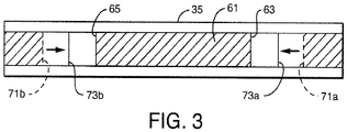
- FIG 3 a sample loop 35 is depicted containing a sample 61.
- the sample 61 is withdrawn into the sample loop with a leading front 63 and a trailing end 65.
- a front bubble 67 and a back bubble 69 separate the sample 65 from solvent or preceding or following samples 71a and 71b.
- a sample 65 has a volume of .01 to 45 microliters.
- the front bubble 67 and back bubble 69 preserve sample integrity and isolation. However, the front bubble 67 and back bubble 69 are placed in sample loop 35 under relatively low pressure with a volume of 0.1 to 3.0 microliters. The gaseous nature of the front bubble 67 and back bubble 69 makes the bubbles compressible. A sudden increase in pressure causes a sudden compression of the front bubble 67 and back bubble 69 moving the solvent or preceding or following samples inward to new compressed positions 73a and 73b. This sudden increase in pressure will result as the first valve 29a assumes a third position as best seen in Figure 2 . In the third position, the sample 61 is discharged through the first valve 29a and through column port 49 as the sample loop 35 is placed in communication with the constant flow port 51. The constant flow port 51 is in communication with pump 13 and has a pressure of 103.421,36 MPa (15,000 PSI) or greater.
- a sudden increase in pressure in sample loop 35 causes pressure and flow perturbations that can be detrimental to sample integrity and downstream components such as column 17 and detector 19.
- the pressure and flow perturbations are also a source of deviation in chromatographic results.
- the pressure source 37 is in fluid communication with at least one of the sample introduction line 31 and the sample loop 35 for placing the sample, held in the sample loop 35, under pressure via second valve or needle movement means 29b. And, upon the valve means 29a and 29b assuming the second position, pressurizing the sample. This pressurization is preferably ramped to avoid sudden changes in the volumes of the front bubble 67 and back bubble 69. The ramp can be quite short from one to 90 seconds. This controlled movement of the solvent or preceding or following samples inward to new compressed positions 73a and 73b preserves sample integrity.
- the pressure source 37 as depicted is a syringe pump but may be other pumps or sources of compressed fluids. In the event the pump 13 and column 17 have a higher operating pressure then can be attained by the pressure source 37, the control means 21 sends a command to the pump 13 to reduce pumping to lower the operating pressure to correspond to the pressure source 37.
- the column line 23b is in fluid communication with the column port 49 for receiving sample from the sample loop 35 and for directing sample to one or more columns 17.
- the column 17 is in fluid communication with the detector 19 via line 23c.
- the constant flow line 23a is for being placed in communication with a source of solvent such as pump 13 with suitable solvent reservoirs [not shown]. Pump 13 has an operation pressure of up to and even exceeding 15,000 PSI.
- the constant flow line has a pressure detector 77 which is in communication with the control means 21.
- sample loop 35 has a pressure detector 79 in communication with the control means allowing the control means 21 to compare values and control pressure source 37 to match the operating pressure.
- the control means 21 can be set with predetermined values based on volumes or pressures to raise the pressure of the sample loop 35 to 75 to 125% of the operating pressure of the pump 13 as the sample 61 is held statically in sample loop 35.
- the post-compression volume is preferably, 85 to 95% of the pre-compression volume.
- first valve 29a in the first position, one of the first loop port 45 and the second loop port 47 is in fluid communication with the sample port 41 and the remaining first loop port 45 and second loop port 47 is in fluid communication with the withdrawal port 43. And, in the first position, the constant flow port 51 is in communication with the column port 49.
- Second valve 29b and/or needle positioning means 55' which forms not part of the present invention, is capable of assuming the second position. In the second position, at least one of the first loop port 45 and the second loop port 47 is in fluid communication with the pressure source, syringe pump 37 or 37'.
- the first loop port 45 and said second loop port 47 are in fluid communication with the constant flow port 51 and the column port 49.
- the valve means 29a and 29b are in signal communication with control means 21.
- the valve means 29a and 29b assume the first position upon receiving a first signal, assumes the second position upon receiving a second signal command and assumes the third position upon receiving a third signal command.
- a command signal those skilled in the art will recognize that the command signal may comprise a series of instructions to effect an operation.
- the sample introduction line 31 is in fluid communication with the sample port 41 and with a source of sample.
- the source of sample may take several forms.
- the source of sample is a needle 55.
- Needle 55 is robotically controlled by control means 21.
- the needle 55 is used to descend into a sample vial 57 where sample is withdrawn.
- the sample injector device 15 would have a plurality of vials 57 and the needle 55 would move from vial to vial.
- Second valve 29b has two positions, one in which the sample receiving line 31 is in communication with sample and a second position in which the valve assumes the second position previously described.
- the needle 55 can be used in the sense of a valve to redirect the sample introduction line 31 robotically to the pressure source 37 to which such needle 55 is placed in fluid communication.
- the needle 55 has two positions. In one position, the needle 55 is placed in a sample vial 57 and upon the withdrawal pump 35 depressurizing the sample introduction line 31, sample is drawn up into such line, in the second position, needle, designated now by the numeral 55' to denote the second position, is placed in fluid communication with the pressure source, syringe pump 37' to pressurize the sample and fluids in the sample loop 35.
- the control means 21 is in signal communication with the pressure source 37, the withdrawal pump 35 and the valve means, first valve 29a and second valve 29b or needle movement means as represented by needle 55'.
- the control means instructs by issuing a first command signal to the valve means 29a and 29b or 55' to assume the first position in which a sample is received in the sample introduction line.
- the control means issues a second command signal to the valve means 29a, 29b and/or 55' to assume the second position and signaling the pressure source 37 or 37' to pressurize the sample loop 35 while the sample is received therein to 70 to 100 % of the system pressure to reduce pressure perturbations as the valve means moves to the third position.
- the operation of the invention will be described with respect to a method as an example for placing a sample in a chromatography system having a system pressure.
- the method comprises the steps of providing a device 15 having a valve means 29a, 29b or 55', a sample introduction line 31, a withdrawal line 33, a sample loop 35, a column line 23b, a constant flow line23a, a withdrawal pump 35, a pressure source 37, and a control means 21, as previously described.
- the device 15 is operated or programmed to operate to place sample in the sample loop 35 under pressure from said pressure source 37 or 37' at 70% to 100% of the system pressure prior to placing the valve means 29a in the third position to reduce pressure perturbations.
Landscapes
- Physics & Mathematics (AREA)
- General Physics & Mathematics (AREA)
- Automation & Control Theory (AREA)
- Engineering & Computer Science (AREA)
- Analytical Chemistry (AREA)
- Biochemistry (AREA)
- General Health & Medical Sciences (AREA)
- Chemical & Material Sciences (AREA)
- Immunology (AREA)
- Pathology (AREA)
- Fluid Mechanics (AREA)
- Life Sciences & Earth Sciences (AREA)
- Health & Medical Sciences (AREA)
- Treatment Of Liquids With Adsorbents In General (AREA)
- Sampling And Sample Adjustment (AREA)
- Automatic Analysis And Handling Materials Therefor (AREA)
Claims (8)
- Un dispositif pour placer un échantillon (61) dans un système chromatographique (11) équipé d'une pression de système,le système chromatographique (11) comprenant une pompe de chromatographie (13), un injecteur d'échantillon (15), une colonne de chromatographie (17), un détecteur (19) et un moyen de commande (21) en communication de signal avec la pompe (13), l'injecteur d'échantillon (15) et le détecteur (19),l'injecteur d'échantillon (15) comprenant un moyen de soupape (29a, 29b) équipé d'une première soupape (29a) et une deuxième soupape (29b), une ligne d'introduction d'échantillon (31), une ligne de retrait (33), une boucle d'échantillonnage (35), une ligne de colonne (23b), une ligne d'écoulement constant (23a), une pompe de retrait, une source de pression (37) et une source d'échantillon, le moyen de commande (21) étant en communication de signal avec la source de pression (37), la pompe de retrait et les première et deuxième soupapes (29a, 29b), ces première et deuxième soupapes (29a, 29b) étant configurées pour placer sélectivement l'échantillon (61) dans la ligne de colonne (23b),la première soupape (29a) comprenant un orifice d'échantillon (41), un orifice de retrait (43), un premier orifice de boucle (45), un deuxième orifice de boucle (47), un orifice de colonne (49) et un orifice d'écoulement constant (51),le moyen de soupape (29a, 29b) ayant une pluralité de positions comprenant une première position des première et deuxième soupapes (29a, 29b), une deuxième position de la deuxième soupape (29b) et une troisième position de la première soupape (29a), les première et deuxième soupapes (29a, 29b) prenant leur première position sur une première commande de signal du moyen de commande (21), la deuxième soupape (29b) prenant sa deuxième position sur une deuxième commande de signal du moyen de commande (21) et la première soupape (29a) prenant sa troisième position sur une troisième commande de signal du moyen de commande (21), dans lequeldans la première position de la deuxième soupape (29b), la ligne d'introduction d'échantillon (31) est en communication fluide avec la source d'échantillon (55), et dans la première position de la première soupape (29a), la ligne d'introduction d'échantillon (31) est en communication fluide avec l'orifice d'échantillon (41) communiquant avec l'un du premier et du deuxième orifices de boucle (45, 47), l'autre de ceux-ci communiquant avec l'orifice de retrait (43), l'orifice d'écoulement constant (51) est en communication avec l'orifice de colonne (49) et l'orifice de retrait (43) est en communication fluide avec la ligne de retrait (33) dépressurisée par la pompe de retrait pour tirer l'échantillon (61) dans la ligne d'introduction d'échantillon (31) et la boucle d'échantillonnage (35) communiquant avec les premier et deuxième orifices de boucle (45, 47), dans la deuxième position de la deuxième soupape (29b), la source de pression (37) est en communication fluide avec la ligne d'introduction d'échantillon (31) et la boucle d'échantillonnage (35) pour placer l'échantillon (61) tenu dans la boucle d'échantillonnage (35) sous pression, le moyen de commande (21) étant réglé avec des valeurs prédéterminées basées sur des volumes ou pressions pour augmenter la pression de la boucle d'échantillonnage (35) de 75 à 125% d'une pression de fonctionnement de la pompe (13) quand l'échantillon (61) est tenu dans la boucle d'échantillonnage (35), et dans la troisième position de la première soupape (29a), la boucle d'échantillonnage (35), via les premier et deuxième orifices de boucle (45, 47), est en communication fluide avec l'orifice d'écoulement constant (51) et l'orifice de colonne (49), l'orifice d'écoulement constant (51) est en communication fluide avec la ligne d'écoulement constant (23a) communiquant avec la pompe (13), et la ligne de colonne (23b) est en communication fluide avec l'orifice de colonne (49) pour recevoir l'échantillon (61) depuis la boucle d'échantillonnage (35) et le diriger vers la colonne (17).
- Le dispositif de la revendication 1, dans lequel ledit échantillon (61) a une extrémité arrière (65) et une face avant (63) dans laquelle une bulle d'air (67, 69) est placée pour séparer l'échantillon (61) du solvant ou des échantillons précédents ou suivants (71a, 71b).
- Le dispositif de la revendication 1, dans lequel ladite boucle d'échantillonnage (35) a un volume dans la plage de 0,5 microlitre à 50 microlitres.
- Le dispositif de la revendication 3, dans lequel ledit échantillon (61) a un volume de 0,1 à 45 microlitres.
- Le dispositif de la revendication 1, dans lequel ledit échantillon (61) a un volume de pré-compression et un volume de post-compression, ledit volume de post-compression étant de 85 à 95% du volume de pré-compression.
- Le dispositif de la revendication 1, dans lequel ladite source de pression (37) place ladite boucle d'échantillonnage (35) sous pression en changeant le volume à une vitesse d'environ 10 à 800 microlitres par minute.
- Le dispositif de la revendication 1, dans lequel ledit échantillon (61) est placé sous pression dans ladite boucle d'échantillonnage (35) dans des conditions statiques.
- L'utilisation du dispositif selon n'importe laquelle des revendications 1 à 6 dans un procédé permettant de placer un échantillon dans un système chromatographique (11) équipé d'une pression de système.
Applications Claiming Priority (2)
| Application Number | Priority Date | Filing Date | Title |
|---|---|---|---|
| US78334706P | 2006-03-17 | 2006-03-17 | |
| PCT/US2007/064152 WO2007109529A2 (fr) | 2006-03-17 | 2007-03-16 | Appareil et méthodes de réduction des perturbations de pression et de flux dans un système chromatographique |
Publications (3)
| Publication Number | Publication Date |
|---|---|
| EP1996930A2 EP1996930A2 (fr) | 2008-12-03 |
| EP1996930A4 EP1996930A4 (fr) | 2011-01-19 |
| EP1996930B1 true EP1996930B1 (fr) | 2018-01-10 |
Family
ID=38523180
Family Applications (1)
| Application Number | Title | Priority Date | Filing Date |
|---|---|---|---|
| EP07758679.0A Revoked EP1996930B1 (fr) | 2006-03-17 | 2007-03-16 | Appareil et méthodes de réduction des perturbations de pression et de flux dans un système chromatographique |
Country Status (4)
| Country | Link |
|---|---|
| US (1) | US8312762B2 (fr) |
| EP (1) | EP1996930B1 (fr) |
| JP (1) | JP5114471B2 (fr) |
| WO (1) | WO2007109529A2 (fr) |
Families Citing this family (14)
| Publication number | Priority date | Publication date | Assignee | Title |
|---|---|---|---|---|
| US8881582B2 (en) * | 2005-01-31 | 2014-11-11 | Waters Technologies Corporation | Method and apparatus for sample injection in liquid chromatography |
| DE102008006266B4 (de) | 2008-01-25 | 2011-06-09 | Dionex Softron Gmbh | Probengeber für die Flüssigkeitschromatographie, insbesondere für die Hochleistungsflüssigkeitschromatographie |
| CN102460145B (zh) | 2009-06-03 | 2015-04-29 | 安捷伦科技有限公司 | 使中间阀状态的压力差平衡的计量装置的样品注射器 |
| US20150285830A1 (en) * | 2012-08-24 | 2015-10-08 | Gang Woong Lee | Sample pretreatment apparatus and sample pretreatment method |
| US20140061133A1 (en) * | 2012-08-31 | 2014-03-06 | Joseph Lewis HERMAN | Method and Apparatus for Split-Flow-Mixing Liquid Chromatography |
| US9945820B2 (en) * | 2012-11-30 | 2018-04-17 | Agilent Technologies, Inc. | Mixer bypass sample injection for liquid chromatography |
| US9945762B2 (en) * | 2014-12-30 | 2018-04-17 | Agilent Technologies, Inc. | Apparatus and method for introducing sample into a separation unit of a chromatography system without disrupting a mobile phase |
| DE202016100451U1 (de) | 2015-06-25 | 2016-02-16 | Dionex Softron Gmbh | Probengeber für die Flüssigkeitschromatographie, insbesondere für die Hochleistungsflüssigkeitschromatographie |
| EP3571501B1 (fr) * | 2017-01-17 | 2025-07-02 | Waters Technologies Corporation | Systèmes de fourniture d'un flux de solvant sous pression |
| US11543390B2 (en) | 2017-07-04 | 2023-01-03 | Shimadzu Corporation | Autosampler and fluid chromatograph |
| CN111164423B (zh) * | 2017-10-04 | 2024-04-09 | 沃特世科技公司 | 用于色谱分析的系统和方法 |
| US11307181B1 (en) * | 2018-07-14 | 2022-04-19 | Sielc Technologies Corporation | HPLC system with mixed-mode columns for measuring charged analytes in complex mixtures |
| JP7655127B2 (ja) | 2021-07-26 | 2025-04-02 | ウシオ電機株式会社 | 液体クロマトグラフおよび液体試料分析方法 |
| DE102021122886A1 (de) | 2021-09-03 | 2023-03-09 | Dionex Softron Gmbh | Laden eines Fluidikelements |
Citations (8)
| Publication number | Priority date | Publication date | Assignee | Title |
|---|---|---|---|---|
| US3915013A (en) | 1974-02-04 | 1975-10-28 | Ethyl Corp | Low pressure gas sample apparatus and method |
| JPS5995458A (ja) | 1982-11-22 | 1984-06-01 | Yanagimoto Seisakusho:Kk | ガスクロマトグラフのサンプリング法 |
| US4957009A (en) * | 1988-09-23 | 1990-09-18 | Spectra-Physics, Inc. | Pushloop liquid sampling method |
| WO2004025272A1 (fr) | 2002-09-11 | 2004-03-25 | Waters Investments Limited | Systeme d'injection d'echantillon a fluide pressurise et procede d'injection correspondant |
| US20050019216A1 (en) | 2003-07-24 | 2005-01-27 | Hans-Heinrich Trutnau | Apparatus for introducing a sample into a flowthrough analysis system |
| JP2006058146A (ja) | 2004-08-20 | 2006-03-02 | Daicel Chem Ind Ltd | 試料注入方法、試料注入装置及びそれを有する超臨界流体クロマトグラフィー装置 |
| WO2006023828A2 (fr) | 2004-08-24 | 2006-03-02 | Waters Investments Limited | Dispositifs, systemes et procedes de synchronisation entre la pompe de compensation de debit et l'injecteur |
| WO2006083776A2 (fr) | 2005-01-31 | 2006-08-10 | Waters Investments Limited | Procede et appareil destines a une injection d'echantillon dans une chromatographie liquide |
Family Cites Families (6)
| Publication number | Priority date | Publication date | Assignee | Title |
|---|---|---|---|---|
| DE3943524A1 (de) * | 1989-08-23 | 1991-02-28 | Gynkotek Ges Fuer Den Bau Wiss | Hplc-analysengeraet |
| US5699665A (en) * | 1996-04-10 | 1997-12-23 | Commercial Intertech Corp. | Control system with induced load isolation and relief |
| US5701933A (en) * | 1996-06-27 | 1997-12-30 | Caterpillar Inc. | Hydraulic control system having a bypass valve |
| JP3815322B2 (ja) | 2001-12-27 | 2006-08-30 | 株式会社島津製作所 | 試料導入装置 |
| JP4459633B2 (ja) * | 2004-01-13 | 2010-04-28 | ダイセル化学工業株式会社 | 試料の注入方法及び注入装置 |
| US20060037607A1 (en) * | 2004-08-19 | 2006-02-23 | Cesar Trujillo | Integrated snorkel mask front-mounted snorkel |
-
2007
- 2007-03-16 EP EP07758679.0A patent/EP1996930B1/fr not_active Revoked
- 2007-03-16 WO PCT/US2007/064152 patent/WO2007109529A2/fr not_active Ceased
- 2007-03-16 US US12/282,895 patent/US8312762B2/en active Active
- 2007-03-16 JP JP2009500623A patent/JP5114471B2/ja not_active Expired - Fee Related
Patent Citations (8)
| Publication number | Priority date | Publication date | Assignee | Title |
|---|---|---|---|---|
| US3915013A (en) | 1974-02-04 | 1975-10-28 | Ethyl Corp | Low pressure gas sample apparatus and method |
| JPS5995458A (ja) | 1982-11-22 | 1984-06-01 | Yanagimoto Seisakusho:Kk | ガスクロマトグラフのサンプリング法 |
| US4957009A (en) * | 1988-09-23 | 1990-09-18 | Spectra-Physics, Inc. | Pushloop liquid sampling method |
| WO2004025272A1 (fr) | 2002-09-11 | 2004-03-25 | Waters Investments Limited | Systeme d'injection d'echantillon a fluide pressurise et procede d'injection correspondant |
| US20050019216A1 (en) | 2003-07-24 | 2005-01-27 | Hans-Heinrich Trutnau | Apparatus for introducing a sample into a flowthrough analysis system |
| JP2006058146A (ja) | 2004-08-20 | 2006-03-02 | Daicel Chem Ind Ltd | 試料注入方法、試料注入装置及びそれを有する超臨界流体クロマトグラフィー装置 |
| WO2006023828A2 (fr) | 2004-08-24 | 2006-03-02 | Waters Investments Limited | Dispositifs, systemes et procedes de synchronisation entre la pompe de compensation de debit et l'injecteur |
| WO2006083776A2 (fr) | 2005-01-31 | 2006-08-10 | Waters Investments Limited | Procede et appareil destines a une injection d'echantillon dans une chromatographie liquide |
Also Published As
| Publication number | Publication date |
|---|---|
| JP5114471B2 (ja) | 2013-01-09 |
| JP2009530623A (ja) | 2009-08-27 |
| EP1996930A4 (fr) | 2011-01-19 |
| WO2007109529A2 (fr) | 2007-09-27 |
| US8312762B2 (en) | 2012-11-20 |
| WO2007109529A3 (fr) | 2008-04-10 |
| US20100043539A1 (en) | 2010-02-25 |
| EP1996930A2 (fr) | 2008-12-03 |
Similar Documents
| Publication | Publication Date | Title |
|---|---|---|
| EP1996930B1 (fr) | Appareil et méthodes de réduction des perturbations de pression et de flux dans un système chromatographique | |
| CN104813164B (zh) | 用于液相色谱的混合器旁路样品注射 | |
| US8673144B2 (en) | Flow rate control | |
| EP2257356B1 (fr) | Surveillance chromatographique et commande de plusieurs flux de traitement | |
| US9632064B2 (en) | Gas chromatograph system employing hydrogen carrier gas | |
| CN106662554B (zh) | 分析装置及分析方法 | |
| US10677766B2 (en) | Volumetric flow regulation in multi-dimensional liquid analysis systems | |
| EP3330705B1 (fr) | Clapet anti-retour microfluidique et dispositifs et systèmes associés | |
| US9791080B2 (en) | Microfluidic interconnect | |
| US10307691B2 (en) | Apparatus and methods for preparative liquid chromatography | |
| EP2788639B1 (fr) | Vanne sélectrice pour systèmes de chromatographie liquide | |
| CN111837032A (zh) | 样品处理和分配各个样品包 | |
| US9297682B1 (en) | Inline flow rate meter with auxiliary fluid injection and detection | |
| EP2035788A2 (fr) | Attenuation des effects de decompression par introduction d'echantillon dans la chromatographie liquide a haute pression | |
| EP3607316B1 (fr) | Composant biocompatible à renfort de structure | |
| GB2593061A (en) | Two-dimensional fluid separation with push-pull modulation | |
| EP2626697B1 (fr) | Dispositif de chromatographie liquide | |
| GB2487941A (en) | Fluid separation system for determining an injection time |
Legal Events
| Date | Code | Title | Description |
|---|---|---|---|
| PUAI | Public reference made under article 153(3) epc to a published international application that has entered the european phase |
Free format text: ORIGINAL CODE: 0009012 |
|
| 17P | Request for examination filed |
Effective date: 20080915 |
|
| AK | Designated contracting states |
Kind code of ref document: A2 Designated state(s): DE GB |
|
| RAP1 | Party data changed (applicant data changed or rights of an application transferred) |
Owner name: WATERS TECHNOLOGIES CORPORATION |
|
| DAX | Request for extension of the european patent (deleted) | ||
| RBV | Designated contracting states (corrected) |
Designated state(s): DE GB |
|
| A4 | Supplementary search report drawn up and despatched |
Effective date: 20101221 |
|
| RIC1 | Information provided on ipc code assigned before grant |
Ipc: G01N 30/20 20060101ALI20101215BHEP Ipc: G01N 30/02 20060101AFI20081003BHEP |
|
| 17Q | First examination report despatched |
Effective date: 20160418 |
|
| STAA | Information on the status of an ep patent application or granted ep patent |
Free format text: STATUS: EXAMINATION IS IN PROGRESS |
|
| GRAP | Despatch of communication of intention to grant a patent |
Free format text: ORIGINAL CODE: EPIDOSNIGR1 |
|
| STAA | Information on the status of an ep patent application or granted ep patent |
Free format text: STATUS: GRANT OF PATENT IS INTENDED |
|
| INTG | Intention to grant announced |
Effective date: 20170823 |
|
| GRAS | Grant fee paid |
Free format text: ORIGINAL CODE: EPIDOSNIGR3 |
|
| GRAA | (expected) grant |
Free format text: ORIGINAL CODE: 0009210 |
|
| STAA | Information on the status of an ep patent application or granted ep patent |
Free format text: STATUS: THE PATENT HAS BEEN GRANTED |
|
| AK | Designated contracting states |
Kind code of ref document: B1 Designated state(s): DE GB |
|
| REG | Reference to a national code |
Ref country code: GB Ref legal event code: FG4D |
|
| REG | Reference to a national code |
Ref country code: DE Ref legal event code: R096 Ref document number: 602007053661 Country of ref document: DE |
|
| REG | Reference to a national code |
Ref country code: DE Ref legal event code: R026 Ref document number: 602007053661 Country of ref document: DE |
|
| PLBI | Opposition filed |
Free format text: ORIGINAL CODE: 0009260 |
|
| PLAX | Notice of opposition and request to file observation + time limit sent |
Free format text: ORIGINAL CODE: EPIDOSNOBS2 |
|
| 26 | Opposition filed |
Opponent name: AGILENT TECHNOLOGIES, INC. Effective date: 20181010 |
|
| PLBB | Reply of patent proprietor to notice(s) of opposition received |
Free format text: ORIGINAL CODE: EPIDOSNOBS3 |
|
| RDAF | Communication despatched that patent is revoked |
Free format text: ORIGINAL CODE: EPIDOSNREV1 |
|
| APBM | Appeal reference recorded |
Free format text: ORIGINAL CODE: EPIDOSNREFNO |
|
| APBP | Date of receipt of notice of appeal recorded |
Free format text: ORIGINAL CODE: EPIDOSNNOA2O |
|
| APAH | Appeal reference modified |
Free format text: ORIGINAL CODE: EPIDOSCREFNO |
|
| APBQ | Date of receipt of statement of grounds of appeal recorded |
Free format text: ORIGINAL CODE: EPIDOSNNOA3O |
|
| PGFP | Annual fee paid to national office [announced via postgrant information from national office to epo] |
Ref country code: GB Payment date: 20220225 Year of fee payment: 16 Ref country code: DE Payment date: 20220217 Year of fee payment: 16 |
|
| APBU | Appeal procedure closed |
Free format text: ORIGINAL CODE: EPIDOSNNOA9O |
|
| REG | Reference to a national code |
Ref country code: DE Ref legal event code: R103 Ref document number: 602007053661 Country of ref document: DE Ref country code: DE Ref legal event code: R064 Ref document number: 602007053661 Country of ref document: DE |
|
| RDAG | Patent revoked |
Free format text: ORIGINAL CODE: 0009271 |
|
| STAA | Information on the status of an ep patent application or granted ep patent |
Free format text: STATUS: PATENT REVOKED |
|
| 27W | Patent revoked |
Effective date: 20221221 |
|
| GBPR | Gb: patent revoked under art. 102 of the ep convention designating the uk as contracting state |
Effective date: 20221221 |