EP3571501B1 - Systèmes de fourniture d'un flux de solvant sous pression - Google Patents
Systèmes de fourniture d'un flux de solvant sous pression Download PDFInfo
- Publication number
- EP3571501B1 EP3571501B1 EP17822035.6A EP17822035A EP3571501B1 EP 3571501 B1 EP3571501 B1 EP 3571501B1 EP 17822035 A EP17822035 A EP 17822035A EP 3571501 B1 EP3571501 B1 EP 3571501B1
- Authority
- EP
- European Patent Office
- Prior art keywords
- solvent
- container
- source
- pressurized
- valve
- Prior art date
- Legal status (The legal status is an assumption and is not a legal conclusion. Google has not performed a legal analysis and makes no representation as to the accuracy of the status listed.)
- Active
Links
Images







Classifications
-
- G—PHYSICS
- G01—MEASURING; TESTING
- G01N—INVESTIGATING OR ANALYSING MATERIALS BY DETERMINING THEIR CHEMICAL OR PHYSICAL PROPERTIES
- G01N30/00—Investigating or analysing materials by separation into components using adsorption, absorption or similar phenomena or using ion-exchange, e.g. chromatography or field flow fractionation
- G01N30/02—Column chromatography
- G01N30/26—Conditioning of the fluid carrier; Flow patterns
- G01N30/28—Control of physical parameters of the fluid carrier
- G01N30/32—Control of physical parameters of the fluid carrier of pressure or speed
-
- B—PERFORMING OPERATIONS; TRANSPORTING
- B01—PHYSICAL OR CHEMICAL PROCESSES OR APPARATUS IN GENERAL
- B01D—SEPARATION
- B01D15/00—Separating processes involving the treatment of liquids with solid sorbents; Apparatus therefor
- B01D15/08—Selective adsorption, e.g. chromatography
- B01D15/10—Selective adsorption, e.g. chromatography characterised by constructional or operational features
- B01D15/16—Selective adsorption, e.g. chromatography characterised by constructional or operational features relating to the conditioning of the fluid carrier
- B01D15/163—Pressure or speed conditioning
-
- B—PERFORMING OPERATIONS; TRANSPORTING
- B65—CONVEYING; PACKING; STORING; HANDLING THIN OR FILAMENTARY MATERIAL
- B65D—CONTAINERS FOR STORAGE OR TRANSPORT OF ARTICLES OR MATERIALS, e.g. BAGS, BARRELS, BOTTLES, BOXES, CANS, CARTONS, CRATES, DRUMS, JARS, TANKS, HOPPERS, FORWARDING CONTAINERS; ACCESSORIES, CLOSURES, OR FITTINGS THEREFOR; PACKAGING ELEMENTS; PACKAGES
- B65D83/00—Containers or packages with special means for dispensing contents
- B65D83/14—Containers for dispensing liquid or semi-liquid contents by internal gaseous pressure, i.e. aerosol containers comprising propellant
-
- G—PHYSICS
- G01—MEASURING; TESTING
- G01N—INVESTIGATING OR ANALYSING MATERIALS BY DETERMINING THEIR CHEMICAL OR PHYSICAL PROPERTIES
- G01N30/00—Investigating or analysing materials by separation into components using adsorption, absorption or similar phenomena or using ion-exchange, e.g. chromatography or field flow fractionation
- G01N30/02—Column chromatography
- G01N30/26—Conditioning of the fluid carrier; Flow patterns
- G01N30/38—Flow patterns
-
- G—PHYSICS
- G01—MEASURING; TESTING
- G01N—INVESTIGATING OR ANALYSING MATERIALS BY DETERMINING THEIR CHEMICAL OR PHYSICAL PROPERTIES
- G01N30/00—Investigating or analysing materials by separation into components using adsorption, absorption or similar phenomena or using ion-exchange, e.g. chromatography or field flow fractionation
- G01N30/02—Column chromatography
- G01N30/26—Conditioning of the fluid carrier; Flow patterns
- G01N30/28—Control of physical parameters of the fluid carrier
- G01N30/32—Control of physical parameters of the fluid carrier of pressure or speed
- G01N2030/326—Control of physical parameters of the fluid carrier of pressure or speed pumps
-
- G—PHYSICS
- G01—MEASURING; TESTING
- G01N—INVESTIGATING OR ANALYSING MATERIALS BY DETERMINING THEIR CHEMICAL OR PHYSICAL PROPERTIES
- G01N30/00—Investigating or analysing materials by separation into components using adsorption, absorption or similar phenomena or using ion-exchange, e.g. chromatography or field flow fractionation
- G01N30/02—Column chromatography
- G01N30/26—Conditioning of the fluid carrier; Flow patterns
- G01N30/28—Control of physical parameters of the fluid carrier
- G01N30/32—Control of physical parameters of the fluid carrier of pressure or speed
- G01N2030/328—Control of physical parameters of the fluid carrier of pressure or speed valves, e.g. check valves of pumps
Definitions
- the present disclosure generally relates to systems, methods and devices for providing pressurized solvent flow in chromatography systems.
- Chromatography systems utilize high pressure mobile phases to carry samples through chromatography columns and effect separations of sample components.
- the high pressure mobile phases are delivered to the columns using one or more pumps.
- the pumps deliver a highly controlled, consistent and reproducible mobile phase flow.
- the solvents that are supplied to the pump to generate the mobile phase are often less controlled.
- the solvent flow(s) are often driven only by action of the downstream pump. For example, the solvent is drawn to the pump by the vacuum created by the operating pump, e.g., a reciprocating pump.
- the solvents, solvent reservoirs, and connections are typically not held under pressure.
- priming When introducing new solvents to a chromatography system, or when changing solvents or solvent tubing the pump can require priming or re-priming. Priming saves time and reduces complications related to air bubbles in the system. Traditionally, priming involves drawing the solvent manually or using a weak vacuum though the solvent tubing to remove old solvent and/or air bubbles from the solvent lines. Yet, automated priming using pressurized solvents has not been attempted.
- US2010/024906 discloses in particular a chromatographic solvent delivery system comprising one pressurized solvent source, one divert valve, a pump and an auxiliary waste outlet.
- the present disclosure relates to systems, methods and devices for providing pressurized solvent flow(s) to systems, such as a chromatography system.
- the solvent can be pressurized to assist in system operation and solvent delivery.
- the systems, methods and devices can provide efficient automatic priming of one or more solvents.
- the chromatographic solvent delivery system comprises a vent valve including a main body having central axis, a top side and a bottom side, the body having an inlet and an outlet wherein the inlet is positioned closer to the bottom side than the outlet, the top side having an opening, and a mechanism to allow gas or air to escape or vent out the top side or opening but prevents solvent from escaping or venting out the same top side or opening.
- the mechanism includes a buoyant ball contained within the main body, e.g., a cylinder, having a shape equal to the internal shape of the main body wherein the ball is able to freely move up and down inside the main body, or a seat and a plunger valve contained at or near the top side.
- the main body can also include a cap having a second outlet, the cap being attached to the top of the main body.
- the chromatographic solvent delivery system comprises: the pressurized solvent source having a first sensor; a backup pressurized solvent source having a second sensor; a second vent valve in fluid communication with the backup pressurized solvent source, wherein the second vent valve includes a buoyant ball disposed within and able to freely move up and down within a main body; a switching valve in fluid communication with the solvent sources; a controller in data communication with the sensors, vent valves, switching valves, divert valve and pump, wherein the second vent valve is located between the backup pressurized solvent source and the pump.
- a pressurized solvent source comprising a solvent container configured to be pressurized.
- the solvent container can comprise a container body and a solvent outlet.
- the solvent outlet can be arranged below and spaced from the container body by a predetermined distance.
- the solvent container can be hermetically sealed, with a single solvent outlet.
- the solvent container can comprise a pouch, cylinder or bag.
- the solvent container can be substantially flexible.
- the solvent container may comprise a vent, to assist with the flow of liquid.
- the solvent source includes a chamber.
- the solvent container can be at least partially received in the chamber.
- the chamber can be substantially rigid.
- the chamber can be less flexible than the solvent container.
- the chamber can have a top opening. The top opening can be optionally closable by a lid.
- the solvent source further includes a force applicator to apply a force on at least a part of the container so as to selectively pressurize the container.
- the force applicator can include one or more of a wedge, cam, lever, roller or plunger.
- the pressurized solvent source can further include a chamber and the force applicator comprises a plunger.
- the solvent container can be at least partially received in the chamber and the plunger engages with the solvent container.
- the plunger can be configured for linear translation within the chamber. This can apply a force to the container to selectively pressurize the container.
- a spring is provided between the chamber and the plunger. This can bias the plunger into engagement with the solvent container to selectively pressurize the container.
- the force applicator comprises: a first wedge member having a first wedge surface and being mounted for linear translation towards the solvent container; and a second wedge member having a second wedge surface and being mounted for linear translation towards the first wedge member, wherein the first and second wedge surfaces are engagable with one another to apply a force to the solvent container to selectively pressurize the container.
- the pressurized solvent source further includes: a chamber having a wall; and a pressure plate hingedly secured to the wall of the chamber; wherein the solvent container is arranged between a first side of the pressure plate and the wall of the chamber, and the force applicator is configured to impart a force on the second side of the pressure plate.
- the force applicator comprises at least one roller mechanism, arranged to engage with the solvent container to apply a force to the solvent container to selectively pressurize the solvent container.
- the roller mechanism can be translatable with respect to the solvent container, to progressively reduce the internal volume of the solvent container.
- the force applicator can be an inflatable bladder configured to apply a force to the solvent container.
- the inflatable bladder can be arranged between the solvent container and the chamber, configured to displace solvent from the solvent container.
- the force applicator can comprise a fluid source in fluid communication with the solvent container, configured to displace solvent from the solvent container.
- the fluid can be an inert gas.
- the chromatographic solvent delivery system comprises: a solvent source comprising a solvent container having a solvent outlet arranged below the solvent container.
- the chromatographic solvent delivery system comprises a pressurized solvent source comprising: a plurality of solvent bays, each solvent bay comprising a force applicator and being configured to receive a solvent container, each force applicator being individually controllable to apply a force to the corresponding solvent container in the corresponding bay.
- Figures 2A-2C show a system in which the piston applies pressure to the bottom of the solvent container, the opposite arrangement is also possible.
- the piston could apply pressure to the top of the solvent container, and the solvent exit may be provided at the base of the arrangement.
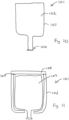
- Fig. 10 shows a pressurized solvent source (101) comprising a solvent container (102) configured to be pressurized.
- the solvent container (102) can comprise a container body (103) and a solvent outlet (104).
- the solvent outlet (104) can be arranged below and spaced from the container body (103) by a predetermined distance. There can be a neck between the container body (103) and the solvent outlet (104). As a result of the position of the solvent outlet (104) below then container body (103), the solvent at the solvent outlet (104) is pressurized due to gravity.
- the solvent container (102) is hermetically sealed, with a single solvent outlet (104).
- the solvent container (102) can comprise a pouch, cylinder or bag.
- the solvent container (102) can be substantially flexible.
- the solvent source (101) includes a chamber (106).
- the solvent container (102) can be at least partially received in the chamber (106).
- the chamber (106) can be substantially rigid.
- the chamber (106) can be less flexible than the solvent container (102).
- the chamber (106) can have a top opening (107).
- the top opening (107) can be optionally closable by a lid (108).
- the lid (108) may preferably hermetically seal the chamber (106).
- the solvent source (101) further includes a force applicator to apply a force on at least a part of the solvent container (102) so as to selectively pressurize the container (102).
- a force applicator to apply a force on at least a part of the solvent container (102) so as to selectively pressurize the container (102).
- the force applicator can comprise a fluid source (110) in fluid communication with the internal volume of the solvent container (102), configured to displace solvent from the solvent container (102). Because the solvent in the solvent container (102) is substantially incompressible, as fluid is provided from the fluid source (110), the increase in pressure between the top of the solvent and the top of the solvent container (102), causes solvent to be displaced from the solvent container (102).
- the force applicator can include an inflatable bladder (111) which can be arranged between the solvent container (102) and the top of a chamber (106).
- the inflatable bladder (111) When the inflatable bladder (111) is connected to a fluid source (110), the inflatable bladder (111) is caused to inflate so as to displace the solvent in the solvent container (102).
- the fluid of the fluid source (110) can be an inert gas.
- applying a manual force to the protrusion (113) imparts a force on the capsule (113) which is sufficient to puncture the capsule (112), and for the pressurised fluid to escape into the void between the top of the solvent and the top of the solvent container (102), thereby imparting a pressure on the solvent container (102).
- the protrusion (113) may include a sharp object on the underside to assist with puncturing the capsule (112).
- Fig. 14 shows a pressurized solvent source (201) including a chamber (206) and a force applicator comprising a plunger (215).
- the solvent container (102) can be at least partially received in the chamber (206), and the plunger (215) engages with the solvent container (102).
- the plunger (215) can be configured for linear translation within the chamber (206).
- the plunger (215) can apply a force to the solvent container (102) to selectively pressurize the container (102).
- a spring (217) is provided between a lid (208) of the chamber (206) and the plunger (215). The spring (217) can bias the plunger (215) into engagement with the solvent container (102) to selectively pressurize the solvent container (102).
- the plunger (215) comprises a plunger head (216) which is sized so as to apply a force over a relatively large surface of the axial end of the solvent container (102).
- the lid (208) is releasably securable to the chamber (206) (e.g. with a screw thread)
- the pressurized solvent source (201) further includes a mounting plate (220), to which the solvent container (102) is connectable or connected.
- the mounting plate (220) may be integrally formed with the end of the solvent container (102).
- the mounting plate (220) has a diameter which is greater than the mouth (221) of the base of the chamber (206), so as to retain the mounting plate (220) and solvent container (102) within the chamber (206), in a similar manner to a sealant/caulking gun.
- Fig. 18 illustrates an embodiment in which the force applicator of the pressurized solvent source (501) includes a roller mechanism.
- the force applicator comprises a roller arrangement (540), comprising a pair of rollers (541A, 541B).
- the rollers (541A, 541B) are urged towards one another, so as to maintain a substantially predetermined gap therebetween.
- the rollers (541A, 541B) are optionally biased towards one another.
- the end of the solvent container (102) distal from the solvent outlet (104) is fed into the roller arrangement (540), and progressively drawn therethrough so as to apply a pressure to the solvent container (102), thereby dispensing the solvent.
- the roller mechanism (540) may be translatable with respect to the solvent container (102) and/or the chamber (506) in which it is installed. As the solvent container (102) is drawn into the roller mechanism (504), it causes the progressive reduction of the internal volume of the solvent container (102), thereby dispensing the solvent.
- the pressurized solvent source (101) shown in Fig. 10 may form part of a chromatographic solvent delivery system comprising a solvent source comprising a solvent container having a solvent outlet arranged below the solvent container, such that a solvent at the solvent outlet is pressurized due to gravity.
- the force applicator (651) is actuated by a motor, air source or other driving device (not shown).
- the force applicator may comprise any of the arrangements shown in figures 12 to 18 and as described herein.
- the pressurized solvent source (600) comprises four solvent bays (650A), to (650B).
- a solvent container embodying the present invention can include a blending and/or mixing mechanism to blend and/or mix the solvent(s) within the solvent container.
- the blending/mixing mechanism may include a rotating mechanical element, which may comprise or be powered by a magnetic drive mechanism.
- FIG. 3 shows a system configured to sense the solvent supply level using a supply actuator piston. Usually operators are required to closely monitor remaining solvent supplies in order to assure run completion.
- the system of the present disclosure can provide a means to monitor the actual remaining solvent capacity at start up as opposed to simply calculating the remaining solvent supply by manually inputting solvent data into a controller.
- FIG. 3 shows a flexible solvent container system having an optical sensor (16) located at the side of the container and chamber.
- the container, the chamber or both can be clear or designed to allow the optical sensor to monitor the solvent level from outside of one or both.
- a magnetic sensor system (not shown) can be used.
- the optical and magnetic sensors can be used separately or can be combined in different configurations for the same or different solvent containers.
- the system shown in FIG. 3 also has a second optical sensor (18) connected to the shaft.
- An optical encoder can obtain the position of the shaft.
- the piston can act as the signaling device.
- the sensor can monitor the position of the shaft, piston or both as a measure of the solvent level in the container.
- the electric load applied to the piston actuator can be used to measure the pressure inside the container.
- the container parameters, solvent, volume, etc. can be identified and used by the controller to determine, with the information from one or more sensors, how much solvent is being used and how much solvent remains in the container.
- the present disclosure also relates to a vent valve to evacuate gas, e.g., air, from a chromatographic solvent supply line.
- the vent valve can be positioned between the chromatographic solvent supply and the pump inlet and can remove all or substantially all of the gas from the solvent supply line, including gas that may be introduced by a solvent supply changeover.
- the vent valve can remove or filter out gas bubbles from the line automatically or with minimal user intervention.
- the present disclosure relates to a vent valve including a main body having central axis, a top side and a bottom side, the body having an inlet and an outlet wherein the inlet is positioned closer to the bottom side than the outlet, the top side or upper portion can have an opening or second outlet.
- the top side opening can have a cap having the second outlet.
- the optional cap can be attached to the cylinder at or near the top.
- the vent valve can further include a mechanism to allow gas or air to escape or exit out the top or upper opening or second outlet but prevents solvent from escaping or exiting out the same top or upper opening or second outlet.
- the mechanism of the vent valve according to the present invention includes a buoyant ball contained within the main body having a diameter equal to the internal diameter of the main body, wherein the ball is able to freely move up and down inside the main body, optionally a seat and a plunger device contained in or on the cap, or both.
- the vent valve can replace or supplement an intake line degasser to prevent or reduce solvent degassing.
- the vent valve can be free standing and not require any external operators.
- the device can shorten a chromatographic pump purge cycle by pre-removal of entrapped gas that may be introduced during solvent supply replenish.
- the vent valve device can reduce the purge cycle by about 20%, 40%, 60%, 80% or about 100 % of the original time required for a purge cycle.
- the vent valve device can remove 50%, 60%, 70%, 80%, 85%, 90%, 95%, 98% or 99% of the gas, e.g., air, from the solvent supply line. These values can be used to define a range, such as about 50% to about 80%, or about 70% to about 90%.
- the vent valve can be positioned downstream of the solvent source and container, and upstream of the pump.
- the vent valve can work as a passive mechanism which senses entrapped gas/air in the solvent supply line. It can remain closed when no gas/air is present and can remain open as the gas/air levels increase.
- the vent valve can activate when gas or air is present in the solvent line and provide a path for its expulsion. When solvent reaches the vent valve, it can close the air/gas expulsion port and preventing solvent from escaping.
- the vent valve can deliver uninterrupted solvent access.
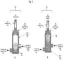
- FIG. 4A shows a vent valve (40) having a buoyant ball (42) in the lower portion of the main body (44).
- FIG. 4A is in an open position and configured to vent gas.
- FIG. 4B shows a vent valve (40) having a buoyant ball (42) in the upper portion of the main body (44).
- FIG. 4B is in a closed position and can be incapable of venting gas.
- the vent valve (40) can have a main body (44), an solvent/gas inlet (46) from the solvent supply, a solvent outlet (48) to the pump inlet, and a top.
- the main body can have a central axis, a top side and a bottom side.
- the main body can have any shape, including a cylindrical shape.
- the solvent/gas inlet (46) and the solvent outlet (48) can be positioned in the lower portion (lower half, third, quarter) of the main body (44).
- the inlet (46) can be positioned closer to the bottom side than the outlet (48).
- the internal volume of the main body (44) can be about, or less than about, 50 mL, 40, 30, 20, 10, 9, 8, 7, 6, 5, 4, 3, 2, 1, 0.9, 0.8, 0.7, 0.6, 0.5, 0.4, 0.3, 0.2, 0.1, 0.09, 0.08, 0.07, 0.06 or about 0.05 mL. These values can be used to define a range, such as about or less than about 3 to about 0.5 mL.
- the top side or the upper portion of the main body (44) can have an opening or a second outlet (50) for gas or air to escape or exit the main body (44).
- the top side opening can also be fitted with a cap having an integral seat (52) to be securely attached to the top side of the main body (44).
- the cap (52) can have a second opening (50) for the gas to escape or exit.
- the cap (52) can also have a fitting (54), e.g., a barbed fitting, to provide a path for solvent overflow.
- the gas flow out is open when the ball (42) is in the lower portion.
- FIG. 4B shows a vent valve (40) with a buoyant ball (42) in the upper portion and in a closed position. As shown in FIG. 4B , the gas flow out is stopped when the ball (42) is engaged with, or in contact with, the outlet (50).
- the vent valve (40) includes a mechanism to allow gas or air to escape or exit out the top or upper opening or second outlet (50) but prevents solvent from escaping or exiting out the same top or upper opening or second outlet (50).
- one such mechanism is a buoyant ball (42), as shown in FIG 4 .
- the ball (42) is contained within the main body (44) and can have a diameter equal to, or substantially equal to, the internal diameter of the main body (44).
- the ball (42) is able to freely move up and down inside the main body (44).
- the ball (42) can allow gas to freely passing by, through or around the ball (42).
- the ball (42) can restrict or prevent solvent from freely passing by, through or around the ball (42).
- solvent interacts with the ball (42) the ball (42) can be forced upwards toward the top side and can block or otherwise prevent the solvent from escaping or exiting the top opening or second outlet (50).
- FIG. 5A shows a vent valve (40) having a buoyant ball (42) in the lower portion and a cap with a plunger and seat mechanism (58).
- the vent valve (40) has a cap with an integral seat (58) on the top of the vessel with an overflow riser tube (56). As shown in FIG. 5A , the gas flow out is open when the ball (42) is in the lower portion.
- FIG. 5B shows a vent valve (40) having a buoyant ball (42) in the upper portion and engaged with the plunger and seat mechanism (58). As shown in FIG. 5B , the gas flow out is stopped by the plunger and seat (58) when the ball (42) is touching, or otherwise engaged with, the plunger (58).
- the solvent container can be replaced.
- the replacement can include removing the supply line or tubing from the solvent container.
- gas or air can inadvertently enter the supply line or tube and become entrapped within the connection.
- the chromatographic pump can be cycled and purged for a period of time to ensure complete removal of any entrapped gas.
- the vent valve can be used to quickly remove any gas from the lines and promote a liquid only supply to the pump.
- the solvent can enter the main body of the vent valve. Gas can migrate up to the upper portion of the main body or chamber, while liquid can be passed through the lower outlet.
- the supply solvent fills causing the mechanism, e.g. ball, to close off the gas evacuation port.
- the vent valve (40) can contain a self-actuating mechanism, such as a seat and a plunger device (58) contained in or on the cap as shown in FIG. 6A and 6B.
- FIG. 6A shows a vent valve (40) having a plunger and seat mechanism (58) in the open position.
- the vent valve (40) has a cap with an integral seat (58) on the top of the vessel with a diaphragm (60) and actuator (62).
- FIG. 6A shows the gas and liquid flow out via the vent port (64) is open when the plunger is low or not engaged.
- FIG. 6B shows a vent valve (40) with plunger and seat (58) in the closed position. As shown in FIG.
- a vent valve (40) can be an active valve as opposed to a passive, self-actuating valve.
- the vent valve (40) can include an actuator (62) connected to an external source to control the actuation of the valve (40). An external force or signal can be used to drive the valve both open and closed.
- the actuator (62) can be in signal communication with a controller.
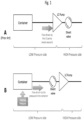
- FIG. 7 shows a chromatographic solvent delivery system with a pressurized solvent source or container (70), a vent valve (40), a divert valve (72) and a chromatography pump (74).
- the vent valve (40) and the divert valve (72) are placed on the low pressure side of the chromatography system, e.g., upstream of the pump (74).
- the vent valve (40) is shown with a buoyant ball (42) in the lower and open position, and in the upper and closed position.
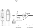
- FIG. 8 shows a chromatographic solvent delivery system with a pressurized solvent source (70) driven by a piston (10), a vent valve (40), a divert valve (72) and a pump (74). Both the vent valve (40) and the divert valve (72) are upstream of the pump (74) in the low pressure side.
- the present disclosure relates to a system having automated liquid container switching.
- chromatography systems do not attempt to monitor solvent levels in solvent containers. Operators are responsible for ensuring there is sufficient solvent supply to complete the desired separation(s). Thus, unattended system operation is limited to the solvent container volume available in a single container.
- the system can employ a combination of liquid sensing and software.
- the chromatography system can detect when one or more solvent containers approaches an empty condition, or a condition wherein the next separation or set of separations cannot be completed, and switch the solvent flow from one or more solvent containers to available containers having sufficient solvent capacity.
- the present disclosure relates to a chromatographic solvent delivery system including at least one pressurized solvent source having a first sensor configured to determine the amount of solvent remaining in the solvent container, at least one backup pressurized solvent source having a second sensor configured to determine the amount of solvent remaining in the solvent container, a switching valve in fluid communication with both solvent sources and a chromatography system, and a controller in data communication with the sensors, the controller having knowledge of future solvent requirements can be configured to switch the fluid connections between the solvent sources and the chromatography system.
- the chromatography system can be set up to analyze a series of samples.
- the solvent container(s) can be monitored by one or more sensors located on or at each of the solvent containers.
- the system can switch the solvent source from the near empty solvent source to a more full solvent source.
- the switching can be automated by the sensors, solvent containers, controller, etc.
- the switch from one solvent source to another can be by activating a switching valve to change to a readily available, full container of solvent.
- the switching valve can be in fluid communication with both solvent sources and a chromatography system.
- the system can have container level sensing technology at each of the solvent locations in the chromatographic system. At each solvent container location, there can be a primary and at least one backup solvent position with a switching valve and tubing connections.
- the system can monitor each of these locations through one or more sensors or sensor types (e.g., optical, mechanical, magnetic).
- sensors or sensor types e.g., optical, mechanical, magnetic.
- the controller can switch the valve from the primary solvent container to a backup container without operator intervention.
- the controller can be in data communication with the one or more sensors.
- the controller can have knowledge of future solvent requirements and can be configured to switch the fluid connections between the solvent sources and the chromatography system.
Landscapes
- Chemical & Material Sciences (AREA)
- Analytical Chemistry (AREA)
- Biochemistry (AREA)
- General Health & Medical Sciences (AREA)
- Physics & Mathematics (AREA)
- Health & Medical Sciences (AREA)
- Life Sciences & Earth Sciences (AREA)
- Pathology (AREA)
- Immunology (AREA)
- General Physics & Mathematics (AREA)
- Chemical Kinetics & Catalysis (AREA)
- Mechanical Engineering (AREA)
- Dispersion Chemistry (AREA)
- Engineering & Computer Science (AREA)
- Containers And Packaging Bodies Having A Special Means To Remove Contents (AREA)
- Details Of Reciprocating Pumps (AREA)
- Reciprocating Pumps (AREA)
- Feeding, Discharge, Calcimining, Fusing, And Gas-Generation Devices (AREA)
Claims (9)
- Système de distribution de solvant chromatographique comprenant :au moins une source de solvant sous pression (101, 201, 301, 401, 501, 600) ;au moins une vanne de dérivation (72) en communication fluidique avec au moins une source de solvant ;au moins une vanne d'évacuation (40) en communication fluidique avec l'au moins une source de solvant et comportant une bille flottante disposée à l'intérieur d'un corps principal et capable de se déplacer librement de haut en bas à l'intérieur de celui-ci ; etune pompe (74) en communication fluidique avec au moins une vanne de dérivation (72),dans lequel l'au moins une vanne d'évacuation (40) est située entre l'au moins une source de solvant sous pression (101, 201, 301, 401, 501, 600) et la pompe (74) ; etdans lequel l'au moins une vanne de dérivation (72) est située entre l'au moins une source de solvant (101, 201, 301, 401, 501, 600) et la pompe (74), et dans lequel au moins une vanne de dérivation (72) est conçue pour dévier au moins un flux de solvant vers la pompe ou vers une voie d'écoulement auxiliaire.
- Système de distribution de solvant chromatographique selon la revendication 1, dans lequel l'au moins une source de solvant sous pression (101, 201, 301, 401, 501, 600) comprend :un récipient de solvant (2, 102) conçu pour être mis sous pression ;un mécanisme (215, 328, 326, 430, 540, 651) pour entrer en prise avec le récipient (2, 102) et conçu pour mettre le récipient sous pression ; etau moins un capteur configuré pour déterminer la pression, le volume ou le flux de solvant à l'intérieur du récipient (2, 102).
- Système de distribution de solvant chromatographique selon la revendication 1, dans lequel au moins une source de solvant sous pression (101, 201, 301, 401, 501, 600) comprend un premier capteur configuré pour déterminer une quantité de solvant restant dans un récipient de solvant (2, 102), le système comprenant en outre :au moins une source de solvant sous pression de secours dotée d'un second capteur configuré pour déterminer la quantité de solvant restant dans le récipient de solvant (2, 102) ;une vanne de commutation en communication fluidique avec les deux sources de solvant et un système de chromatographie ; etun dispositif de commande en communication de données avec les capteurs, le dispositif de commande ayant connaissance des besoins futurs en solvant et configuré pour commuter les connexions de fluides entre les sources de solvant et le système de chromatographie.
- Système de distribution de solvant chromatographique selon la revendication 1, dans lequel l'au moins une source de solvant sous pression (101) comprend un récipient de solvant (102) avec une sortie de solvant (104) agencée sous le récipient de solvant (102).
- Système de distribution de solvant chromatographique selon la revendication 1 comprenant :l'au moins une source de solvant sous pression (101, 201, 301, 401, 501, 600) est dotée d'un premier capteur ;une source de solvant sous pression de secours dotée d'un second capteur ;une seconde vanne d'évacuation en communication fluidique avec la source de solvant sous pression de secours, dans lequel la seconde vanne d'évacuation comprend une bille flottante (42) disposée à l'intérieur d'un corps principal (44) et capable de se déplacer librement de haut en bas à l'intérieur d'un corps principal ;une vanne de commutation en communication fluidique avec les sources de solvants ;un dispositif de commande en communication de données avec les capteurs, les vannes d'évacuation, les vannes de commutation, la vanne de dérivation et la pompe, dans lequella seconde vanne d'évacuation est située entre la source de solvant sous pression de secours (101, 201, 301, 401, 501, 600) et la pompe (74).
- Système de distribution de solvant chromatographique selon la revendication 5, dans lequel la source de solvant sous pression (101) et la source de solvant sous pression de secours comportent chacune un récipient de solvant (102) avec une sortie de solvant (104) disposée sous le récipient de solvant (102).
- Système de distribution de solvant chromatographique selon la revendication 5, comprenant en outre : une pluralité de baies de solvant (650), chaque baie (650) comprenant un applicateur de force (651) et étant conçue pour recevoir un récipient de solvant (102), chaque applicateur de force (651) pouvant être commandé individuellement pour appliquer une force au récipient de solvant correspondant (102) dans la baie correspondante (650).
- Système de distribution de solvant chromatographique selon la revendication 1, dans lequel l'au moins une vanne d'évacuation (40) présente un axe central, un côté supérieur et un côté inférieur, le corps principal présentant une entrée (46) et une sortie (48), dans lequel l'entrée (46) est positionnée plus près du côté inférieur que la sortie (48), le côté supérieur présentant une ouverture.
- Système de distribution de solvant chromatographique selon la revendication 5, dans lequel l'au moins une vanne d'évacuation (40) et/ou la seconde vanne d'évacuation présente un axe central, un côté supérieur et un côté inférieur, le corps principal (44) présentant une entrée (46) et une sortie (48), dans lequel l'entrée (46) est positionnée plus près du côté inférieur que la sortie (48), le côté supérieur présentant une ouverture.
Applications Claiming Priority (2)
| Application Number | Priority Date | Filing Date | Title |
|---|---|---|---|
| US201762447227P | 2017-01-17 | 2017-01-17 | |
| PCT/IB2017/058166 WO2018134662A1 (fr) | 2017-01-17 | 2017-12-19 | Systèmes, procédés et dispositifs de fourniture d'un flux de solvant sous pression |
Publications (2)
| Publication Number | Publication Date |
|---|---|
| EP3571501A1 EP3571501A1 (fr) | 2019-11-27 |
| EP3571501B1 true EP3571501B1 (fr) | 2025-07-02 |
Family
ID=60813887
Family Applications (1)
| Application Number | Title | Priority Date | Filing Date |
|---|---|---|---|
| EP17822035.6A Active EP3571501B1 (fr) | 2017-01-17 | 2017-12-19 | Systèmes de fourniture d'un flux de solvant sous pression |
Country Status (5)
| Country | Link |
|---|---|
| US (1) | US10823713B2 (fr) |
| EP (1) | EP3571501B1 (fr) |
| JP (1) | JP2020505592A (fr) |
| CN (1) | CN110168361B (fr) |
| WO (1) | WO2018134662A1 (fr) |
Families Citing this family (3)
| Publication number | Priority date | Publication date | Assignee | Title |
|---|---|---|---|---|
| JP6532181B2 (ja) * | 2016-02-26 | 2019-06-19 | 三菱重工コンプレッサ株式会社 | 弁システム及び蒸気タービン |
| CN112220677A (zh) * | 2020-10-14 | 2021-01-15 | 深圳赛桥生物创新技术有限公司 | 消除注射泵死区的方法及注射泵 |
| CA3219699A1 (fr) * | 2021-05-21 | 2022-11-24 | Andrew S. Dierker | Raccordement de processus sanitaire a usage unique avec stockage humide integre destine a etre utilise avec des capteurs de processus |
Family Cites Families (53)
| Publication number | Priority date | Publication date | Assignee | Title |
|---|---|---|---|---|
| US725640A (en) * | 1902-01-04 | 1903-04-14 | John Lucas | Valve. |
| US2705502A (en) * | 1949-11-30 | 1955-04-05 | Globe Hoist Co | Air venting device for the cylinder of a hydraulic vehicle lift |
| US2603493A (en) * | 1950-02-06 | 1952-07-15 | Carlo F Rusconi | Automatically vented liquid flow regulating valve |
| US2935990A (en) * | 1958-05-08 | 1960-05-10 | Leslie G Biddle | Air and vapor eliminator for pipe lines |
| US3113103A (en) * | 1960-12-20 | 1963-12-03 | American Cyanamid Co | Rapid centrifugal chromatography |
| US3185303A (en) * | 1964-05-21 | 1965-05-25 | George M Munson | Hydraulic system with automatic flow direction control valve |
| US3446057A (en) * | 1966-10-14 | 1969-05-27 | Varian Associates | Method and apparatus for chromatography |
| US3746263A (en) * | 1971-04-05 | 1973-07-17 | W Reeder | Weeper assembly and method for use in a slow diffusion type irrigation system |
| US3733449A (en) * | 1971-09-22 | 1973-05-15 | George C Chiga Guthric | Pump protection system with pressure responsive switch and float valve |
| US3896675A (en) * | 1973-11-23 | 1975-07-29 | United Aircraft Corp | High speed hydraulic sensor |
| JPS55122149A (en) * | 1979-03-14 | 1980-09-19 | Japan Spectroscopic Co | Method and apparatus for supplying solvent in liquid chromatograph |
| US4599049A (en) * | 1982-01-11 | 1986-07-08 | Hewlett-Packard Company | High pressure meter pump |
| US4448684A (en) * | 1983-01-28 | 1984-05-15 | The Perkin-Elmer Corporation | Solvent pressurization system |
| US4981597A (en) * | 1986-03-10 | 1991-01-01 | Isco, Inc. | Gradient system |
| GB2195473B (en) * | 1986-09-17 | 1990-08-15 | Philips Electronic Associated | Liquid chromatograph |
| US4836038A (en) * | 1988-03-18 | 1989-06-06 | Aim Instruments Ltd. | Automated sampler-injector apparatus and method for sampling a quantity of sample and testing portions of said quantity |
| CN2052089U (zh) * | 1989-05-14 | 1990-01-31 | 刘锡海 | 带有气液分离室的自动排气阀 |
| CN2055560U (zh) * | 1989-07-01 | 1990-04-04 | 北京化工学院 | 自由浮球式自动排液器 |
| US5108928A (en) * | 1989-11-13 | 1992-04-28 | General Dynamics Corporation | Method and apparatus for delivering a sample to multiple analytical instruments |
| US4994180A (en) * | 1990-02-01 | 1991-02-19 | Systec, Inc. | Solvent handling system |
| US5044397A (en) * | 1990-03-02 | 1991-09-03 | Emil Szlaga | Tank pressure control apparatus |
| US5265642A (en) | 1991-08-27 | 1993-11-30 | Sp Industries Limited Partnership | Pressure relief valve in a cap |
| US5241998A (en) * | 1991-10-30 | 1993-09-07 | Suprex Corporation | Apparatus and method for packing particles |
| US5435335A (en) * | 1994-06-17 | 1995-07-25 | Ebw, Inc. | Overflow valve |
| US6058964A (en) * | 1997-12-15 | 2000-05-09 | Walbro Corporation | Multi-level fuel pickup |
| US20020059945A1 (en) * | 1998-05-29 | 2002-05-23 | Romaine Maiefski | Sample wash station assembly |
| US6012488A (en) * | 1998-09-17 | 2000-01-11 | Rheodyne, L.P. | Segmenting valve |
| US5993654A (en) * | 1998-09-24 | 1999-11-30 | Eldex Laboratories, Inc. | Pressurized liquid delivery apparatus |
| US6257052B1 (en) * | 1999-07-06 | 2001-07-10 | Digichrom, Inc | Pump, sample feed and valving for high performance liquid chromatography (HPLC) |
| US6299767B1 (en) * | 1999-10-29 | 2001-10-09 | Waters Investments Limited | High pressure capillary liquid chromatography solvent delivery system |
| AUPQ616200A0 (en) * | 2000-03-10 | 2000-03-30 | Speight, Christopher | Chemical metering pump |
| WO2002023163A1 (fr) * | 2000-09-15 | 2002-03-21 | California Institute Of Technology | Dispositifs a debit transversal microfabriques et procedes associes |
| US7033500B2 (en) * | 2001-06-25 | 2006-04-25 | Lipid Sciences, Inc. | Systems and methods using multiple solvents for the removal of lipids from fluids |
| US6854346B2 (en) * | 2001-09-17 | 2005-02-15 | Pgi International, Ltd. | Purging system for use with a gas sampling system |
| DE10393201T5 (de) * | 2002-09-11 | 2005-09-01 | Waters Investments Ltd., Milford | Hochdruckfluidprobeninjektionsvorrichtung und Verfahren |
| US7882801B2 (en) * | 2003-08-29 | 2011-02-08 | David Eric Akerman | Milk sampling and testing |
| US7686959B2 (en) * | 2004-05-05 | 2010-03-30 | Biotage Ab | Control system and method for flash separation |
| US7419598B2 (en) * | 2005-03-08 | 2008-09-02 | Teledyne Isco, Inc. | Chromatographic solvent monitor |
| US8997740B2 (en) * | 2005-09-27 | 2015-04-07 | Ric Investments, Llc | Humidifier with back-flow prevention valve |
| US8241013B2 (en) | 2005-10-27 | 2012-08-14 | Waters Technologies Corporation | Serial capillary pump |
| EP1996930B1 (fr) * | 2006-03-17 | 2018-01-10 | Waters Technologies Corporation | Appareil et méthodes de réduction des perturbations de pression et de flux dans un système chromatographique |
| US20100132805A1 (en) * | 2006-04-19 | 2010-06-03 | B/E Intellectual Property | Air vent valve for beverage makers |
| US8672289B2 (en) * | 2008-04-21 | 2014-03-18 | Pride Technologies International Pty Ltd | Domestic water tap or faucet with floating buoyant ball valve and activation rod |
| CN101639127A (zh) * | 2009-08-26 | 2010-02-03 | 王旭华 | 一种排气阀 |
| US8546752B2 (en) * | 2009-12-07 | 2013-10-01 | Advion Inc. | Solid-phase extraction (SPE) tips and methods of use |
| US20120205314A1 (en) * | 2010-08-13 | 2012-08-16 | Davison Dale A | Gradient start up system |
| WO2012022620A1 (fr) | 2010-08-17 | 2012-02-23 | Grünenthal GmbH | Procédé et dispositif d'alimentation d'appareils d'analyse et de systèmes de manutention de liquides avec des liquides |
| WO2013086281A1 (fr) * | 2011-12-09 | 2013-06-13 | Waters Technologies Corporation | Vanne sélectrice pour systèmes de chromatographie liquide |
| US10238989B2 (en) * | 2011-12-14 | 2019-03-26 | Waters Technologies Corporation | Hybrid gradient delivery system and operation |
| WO2014018520A1 (fr) * | 2012-07-23 | 2014-01-30 | Arkis Biosciences | Dispositif de régulation de pression gravitationnelle dans un système de shunt |
| US10765968B2 (en) * | 2014-08-19 | 2020-09-08 | Supercritical Fluid Technologies, Inc. | Systems and methods for supercritical fluid chromatography |
| US9903503B2 (en) * | 2014-11-26 | 2018-02-27 | B/E Aerospace, Inc. | Aircraft water heating tank air vent valve |
| US10103015B2 (en) * | 2016-04-29 | 2018-10-16 | Dh Technologies Development Pte. Ltd. | Sampling interface for mass spectrometry systems and methods |
-
2017
- 2017-12-19 EP EP17822035.6A patent/EP3571501B1/fr active Active
- 2017-12-19 US US15/847,586 patent/US10823713B2/en active Active
- 2017-12-19 WO PCT/IB2017/058166 patent/WO2018134662A1/fr not_active Ceased
- 2017-12-19 JP JP2019538367A patent/JP2020505592A/ja active Pending
- 2017-12-19 CN CN201780083790.6A patent/CN110168361B/zh active Active
Also Published As
| Publication number | Publication date |
|---|---|
| JP2020505592A (ja) | 2020-02-20 |
| CN110168361B (zh) | 2022-08-12 |
| US10823713B2 (en) | 2020-11-03 |
| CN110168361A (zh) | 2019-08-23 |
| WO2018134662A1 (fr) | 2018-07-26 |
| EP3571501A1 (fr) | 2019-11-27 |
| US20180202980A1 (en) | 2018-07-19 |
Similar Documents
| Publication | Publication Date | Title |
|---|---|---|
| US20220334090A1 (en) | Sampler for liquid chromatography | |
| EP3571501B1 (fr) | Systèmes de fourniture d'un flux de solvant sous pression | |
| CN110431104B (zh) | 用于粘性物料的清空装置以及相关方法 | |
| KR102004249B1 (ko) | 기포 제거와 형성 방지를 위한 액체 시린지 충진기 | |
| US20020158079A1 (en) | Liquid dispensing system with enhanced filter | |
| JP7416546B2 (ja) | グリース定量化装置 | |
| JP7307267B2 (ja) | 液体クロマトグラフ装置および液体クロマトグラフ装置の気泡除去方法 | |
| US20230339630A1 (en) | Filling apparatus | |
| KR20220001595A (ko) | 주사기 충전 장치 및 방법 | |
| JP4077674B2 (ja) | ナノ/ミクロ液体クロマトグラフのグラジエント送液装置および送液方法 | |
| CN101600502B (zh) | 用于向充气的舱室内配量液体的装置和方法 | |
| AU2021407384B2 (en) | Method for refilling a container with a dispensing pump and corresponding refilling cartridge, and machine | |
| JP2002523221A (ja) | 単一ストローク流体定量吐出装置 | |
| JP2015150537A (ja) | 材料供給装置 | |
| CN112105451B (zh) | 用于生产和分配反应混合物的设备和方法 | |
| JP7808182B2 (ja) | シリンジを充填するための装置及び方法 | |
| JP6846252B2 (ja) | 液状物の計量充填装置 | |
| JP2665439B2 (ja) | 流体充填機用充填バルブ | |
| US20080087686A1 (en) | Apparatus and method for expelling a substance from a container | |
| JP2023117988A (ja) | 液体クロマトグラフ | |
| JP2022017904A (ja) | ディスペンサ | |
| JP2004142395A (ja) | 缶入りインキの抽出装置及び缶入りインキの抽出方法 | |
| JPH0465979B2 (fr) | ||
| JPH059635U (ja) | 流体滴下供給装置 |
Legal Events
| Date | Code | Title | Description |
|---|---|---|---|
| STAA | Information on the status of an ep patent application or granted ep patent |
Free format text: STATUS: UNKNOWN |
|
| STAA | Information on the status of an ep patent application or granted ep patent |
Free format text: STATUS: THE INTERNATIONAL PUBLICATION HAS BEEN MADE |
|
| PUAI | Public reference made under article 153(3) epc to a published international application that has entered the european phase |
Free format text: ORIGINAL CODE: 0009012 |
|
| STAA | Information on the status of an ep patent application or granted ep patent |
Free format text: STATUS: REQUEST FOR EXAMINATION WAS MADE |
|
| 17P | Request for examination filed |
Effective date: 20190715 |
|
| AK | Designated contracting states |
Kind code of ref document: A1 Designated state(s): AL AT BE BG CH CY CZ DE DK EE ES FI FR GB GR HR HU IE IS IT LI LT LU LV MC MK MT NL NO PL PT RO RS SE SI SK SM TR |
|
| AX | Request for extension of the european patent |
Extension state: BA ME |
|
| DAV | Request for validation of the european patent (deleted) | ||
| DAX | Request for extension of the european patent (deleted) | ||
| STAA | Information on the status of an ep patent application or granted ep patent |
Free format text: STATUS: EXAMINATION IS IN PROGRESS |
|
| 17Q | First examination report despatched |
Effective date: 20221013 |
|
| REG | Reference to a national code |
Ref country code: DE Free format text: PREVIOUS MAIN CLASS: G01N0030320000 Ipc: B01D0015160000 Ref country code: DE Ref legal event code: R079 Ref document number: 602017090330 Country of ref document: DE Free format text: PREVIOUS MAIN CLASS: G01N0030320000 Ipc: B01D0015160000 |
|
| RIC1 | Information provided on ipc code assigned before grant |
Ipc: G01N 30/32 20060101ALI20241217BHEP Ipc: B01D 15/16 20060101AFI20241217BHEP |
|
| GRAP | Despatch of communication of intention to grant a patent |
Free format text: ORIGINAL CODE: EPIDOSNIGR1 |
|
| STAA | Information on the status of an ep patent application or granted ep patent |
Free format text: STATUS: GRANT OF PATENT IS INTENDED |
|
| INTG | Intention to grant announced |
Effective date: 20250131 |
|
| GRAS | Grant fee paid |
Free format text: ORIGINAL CODE: EPIDOSNIGR3 |
|
| GRAA | (expected) grant |
Free format text: ORIGINAL CODE: 0009210 |
|
| STAA | Information on the status of an ep patent application or granted ep patent |
Free format text: STATUS: THE PATENT HAS BEEN GRANTED |
|
| P01 | Opt-out of the competence of the unified patent court (upc) registered |
Free format text: CASE NUMBER: APP_22119/2025 Effective date: 20250509 |
|
| AK | Designated contracting states |
Kind code of ref document: B1 Designated state(s): AL AT BE BG CH CY CZ DE DK EE ES FI FR GB GR HR HU IE IS IT LI LT LU LV MC MK MT NL NO PL PT RO RS SE SI SK SM TR |
|
| REG | Reference to a national code |
Ref country code: GB Ref legal event code: FG4D |
|
| REG | Reference to a national code |
Ref country code: CH Ref legal event code: EP |
|
| REG | Reference to a national code |
Ref country code: DE Ref legal event code: R096 Ref document number: 602017090330 Country of ref document: DE |
|
| REG | Reference to a national code |
Ref country code: IE Ref legal event code: FG4D |
|
| REG | Reference to a national code |
Ref country code: NL Ref legal event code: MP Effective date: 20250702 |
|
| PG25 | Lapsed in a contracting state [announced via postgrant information from national office to epo] |
Ref country code: PT Free format text: LAPSE BECAUSE OF FAILURE TO SUBMIT A TRANSLATION OF THE DESCRIPTION OR TO PAY THE FEE WITHIN THE PRESCRIBED TIME-LIMIT Effective date: 20251103 |
|
| PG25 | Lapsed in a contracting state [announced via postgrant information from national office to epo] |
Ref country code: NL Free format text: LAPSE BECAUSE OF FAILURE TO SUBMIT A TRANSLATION OF THE DESCRIPTION OR TO PAY THE FEE WITHIN THE PRESCRIBED TIME-LIMIT Effective date: 20250702 |
|
| REG | Reference to a national code |
Ref country code: AT Ref legal event code: MK05 Ref document number: 1808638 Country of ref document: AT Kind code of ref document: T Effective date: 20250702 |
|
| PG25 | Lapsed in a contracting state [announced via postgrant information from national office to epo] |
Ref country code: IS Free format text: LAPSE BECAUSE OF FAILURE TO SUBMIT A TRANSLATION OF THE DESCRIPTION OR TO PAY THE FEE WITHIN THE PRESCRIBED TIME-LIMIT Effective date: 20251102 |
|
| PGFP | Annual fee paid to national office [announced via postgrant information from national office to epo] |
Ref country code: DE Payment date: 20251126 Year of fee payment: 9 |
|
| PGFP | Annual fee paid to national office [announced via postgrant information from national office to epo] |
Ref country code: GB Payment date: 20251119 Year of fee payment: 9 |
|
| PG25 | Lapsed in a contracting state [announced via postgrant information from national office to epo] |
Ref country code: NO Free format text: LAPSE BECAUSE OF FAILURE TO SUBMIT A TRANSLATION OF THE DESCRIPTION OR TO PAY THE FEE WITHIN THE PRESCRIBED TIME-LIMIT Effective date: 20251002 |
|
| REG | Reference to a national code |
Ref country code: LT Ref legal event code: MG9D |
|
| PG25 | Lapsed in a contracting state [announced via postgrant information from national office to epo] |
Ref country code: AT Free format text: LAPSE BECAUSE OF FAILURE TO SUBMIT A TRANSLATION OF THE DESCRIPTION OR TO PAY THE FEE WITHIN THE PRESCRIBED TIME-LIMIT Effective date: 20250702 |
|
| PG25 | Lapsed in a contracting state [announced via postgrant information from national office to epo] |
Ref country code: FI Free format text: LAPSE BECAUSE OF FAILURE TO SUBMIT A TRANSLATION OF THE DESCRIPTION OR TO PAY THE FEE WITHIN THE PRESCRIBED TIME-LIMIT Effective date: 20250702 |
|
| PG25 | Lapsed in a contracting state [announced via postgrant information from national office to epo] |
Ref country code: HR Free format text: LAPSE BECAUSE OF FAILURE TO SUBMIT A TRANSLATION OF THE DESCRIPTION OR TO PAY THE FEE WITHIN THE PRESCRIBED TIME-LIMIT Effective date: 20250702 |
|
| PG25 | Lapsed in a contracting state [announced via postgrant information from national office to epo] |
Ref country code: GR Free format text: LAPSE BECAUSE OF FAILURE TO SUBMIT A TRANSLATION OF THE DESCRIPTION OR TO PAY THE FEE WITHIN THE PRESCRIBED TIME-LIMIT Effective date: 20251003 |
|
| PG25 | Lapsed in a contracting state [announced via postgrant information from national office to epo] |
Ref country code: SE Free format text: LAPSE BECAUSE OF FAILURE TO SUBMIT A TRANSLATION OF THE DESCRIPTION OR TO PAY THE FEE WITHIN THE PRESCRIBED TIME-LIMIT Effective date: 20250702 Ref country code: CZ Free format text: LAPSE BECAUSE OF FAILURE TO SUBMIT A TRANSLATION OF THE DESCRIPTION OR TO PAY THE FEE WITHIN THE PRESCRIBED TIME-LIMIT Effective date: 20250702 |
|
| PG25 | Lapsed in a contracting state [announced via postgrant information from national office to epo] |
Ref country code: LV Free format text: LAPSE BECAUSE OF FAILURE TO SUBMIT A TRANSLATION OF THE DESCRIPTION OR TO PAY THE FEE WITHIN THE PRESCRIBED TIME-LIMIT Effective date: 20250702 |
|
| PG25 | Lapsed in a contracting state [announced via postgrant information from national office to epo] |
Ref country code: BG Free format text: LAPSE BECAUSE OF FAILURE TO SUBMIT A TRANSLATION OF THE DESCRIPTION OR TO PAY THE FEE WITHIN THE PRESCRIBED TIME-LIMIT Effective date: 20250702 Ref country code: PL Free format text: LAPSE BECAUSE OF FAILURE TO SUBMIT A TRANSLATION OF THE DESCRIPTION OR TO PAY THE FEE WITHIN THE PRESCRIBED TIME-LIMIT Effective date: 20250702 |
|
| PG25 | Lapsed in a contracting state [announced via postgrant information from national office to epo] |
Ref country code: RS Free format text: LAPSE BECAUSE OF FAILURE TO SUBMIT A TRANSLATION OF THE DESCRIPTION OR TO PAY THE FEE WITHIN THE PRESCRIBED TIME-LIMIT Effective date: 20251002 |
|
| PG25 | Lapsed in a contracting state [announced via postgrant information from national office to epo] |
Ref country code: ES Free format text: LAPSE BECAUSE OF FAILURE TO SUBMIT A TRANSLATION OF THE DESCRIPTION OR TO PAY THE FEE WITHIN THE PRESCRIBED TIME-LIMIT Effective date: 20250702 |
|
| PG25 | Lapsed in a contracting state [announced via postgrant information from national office to epo] |
Ref country code: RO Free format text: LAPSE BECAUSE OF FAILURE TO SUBMIT A TRANSLATION OF THE DESCRIPTION OR TO PAY THE FEE WITHIN THE PRESCRIBED TIME-LIMIT Effective date: 20250702 |
|
| PG25 | Lapsed in a contracting state [announced via postgrant information from national office to epo] |
Ref country code: SM Free format text: LAPSE BECAUSE OF FAILURE TO SUBMIT A TRANSLATION OF THE DESCRIPTION OR TO PAY THE FEE WITHIN THE PRESCRIBED TIME-LIMIT Effective date: 20250702 |
|
| PG25 | Lapsed in a contracting state [announced via postgrant information from national office to epo] |
Ref country code: DK Free format text: LAPSE BECAUSE OF FAILURE TO SUBMIT A TRANSLATION OF THE DESCRIPTION OR TO PAY THE FEE WITHIN THE PRESCRIBED TIME-LIMIT Effective date: 20250702 |
|
| PG25 | Lapsed in a contracting state [announced via postgrant information from national office to epo] |
Ref country code: IT Free format text: LAPSE BECAUSE OF FAILURE TO SUBMIT A TRANSLATION OF THE DESCRIPTION OR TO PAY THE FEE WITHIN THE PRESCRIBED TIME-LIMIT Effective date: 20250702 |
|
| PG25 | Lapsed in a contracting state [announced via postgrant information from national office to epo] |
Ref country code: SK Free format text: LAPSE BECAUSE OF FAILURE TO SUBMIT A TRANSLATION OF THE DESCRIPTION OR TO PAY THE FEE WITHIN THE PRESCRIBED TIME-LIMIT Effective date: 20250702 Ref country code: EE Free format text: LAPSE BECAUSE OF FAILURE TO SUBMIT A TRANSLATION OF THE DESCRIPTION OR TO PAY THE FEE WITHIN THE PRESCRIBED TIME-LIMIT Effective date: 20250702 |