EP1997756A2 - Dispositif d'enroulement - Google Patents
Dispositif d'enroulement Download PDFInfo
- Publication number
- EP1997756A2 EP1997756A2 EP08151875A EP08151875A EP1997756A2 EP 1997756 A2 EP1997756 A2 EP 1997756A2 EP 08151875 A EP08151875 A EP 08151875A EP 08151875 A EP08151875 A EP 08151875A EP 1997756 A2 EP1997756 A2 EP 1997756A2
- Authority
- EP
- European Patent Office
- Prior art keywords
- winding
- support roller
- winding device
- individual
- stations
- Prior art date
- Legal status (The legal status is an assumption and is not a legal conclusion. Google has not performed a legal analysis and makes no representation as to the accuracy of the status listed.)
- Withdrawn
Links
Images


Classifications
-
- B—PERFORMING OPERATIONS; TRANSPORTING
- B65—CONVEYING; PACKING; STORING; HANDLING THIN OR FILAMENTARY MATERIAL
- B65H—HANDLING THIN OR FILAMENTARY MATERIAL, e.g. SHEETS, WEBS, CABLES
- B65H18/00—Winding webs
- B65H18/08—Web-winding mechanisms
- B65H18/26—Mechanisms for controlling contact pressure on winding-web package, e.g. for regulating the quantity of air between web layers
-
- B—PERFORMING OPERATIONS; TRANSPORTING
- B65—CONVEYING; PACKING; STORING; HANDLING THIN OR FILAMENTARY MATERIAL
- B65H—HANDLING THIN OR FILAMENTARY MATERIAL, e.g. SHEETS, WEBS, CABLES
- B65H18/00—Winding webs
- B65H18/02—Supporting web roll
- B65H18/021—Multiple web roll supports
-
- B—PERFORMING OPERATIONS; TRANSPORTING
- B65—CONVEYING; PACKING; STORING; HANDLING THIN OR FILAMENTARY MATERIAL
- B65H—HANDLING THIN OR FILAMENTARY MATERIAL, e.g. SHEETS, WEBS, CABLES
- B65H2301/00—Handling processes for sheets or webs
- B65H2301/40—Type of handling process
- B65H2301/41—Winding, unwinding
- B65H2301/414—Winding
- B65H2301/4148—Winding slitting
-
- B—PERFORMING OPERATIONS; TRANSPORTING
- B65—CONVEYING; PACKING; STORING; HANDLING THIN OR FILAMENTARY MATERIAL
- B65H—HANDLING THIN OR FILAMENTARY MATERIAL, e.g. SHEETS, WEBS, CABLES
- B65H2301/00—Handling processes for sheets or webs
- B65H2301/40—Type of handling process
- B65H2301/41—Winding, unwinding
- B65H2301/414—Winding
- B65H2301/4148—Winding slitting
- B65H2301/41486—Winding slitting winding on two or more winding shafts simultaneously
- B65H2301/414863—Winding slitting winding on two or more winding shafts simultaneously directly against central support roller
Definitions
- the invention relates to a winding device for winding webs of material, in particular fibrous webs in the form of paper, cardboard or tissue webs on sleeves or hubs, with a longitudinal cutting device for dividing the web into individual webs and individual winding stations, which are arranged in two winding lines on both sides of a drivable support roller on which the winding rolls on or lie on winding.
- Winding devices in the form of back-up roll winders are previously known in a variety of different prior art designs. Representative is here on the publication DE 44 24 848 A1 directed.
- these subsequent wind-up stations are assigned, which wind each of the individual webs into a wound reel.
- the individual winding stations are arranged in two winding lines on both sides of a central support roller. These consist of two movable transversely to the direction of web travel support elements, to each of which a rotatable, retractable on one side of the winding tube guide head is attached.
- the guide heads bear wholly or partly the weight of the bobbins when winding and are either free-running or connected to a rotary drive to additionally influence the tension during winding can.
- the winding quality is crucial by the contact force or contact force in the winding nip or nip at the contact line between the winding rollers and the support roller through Pressing the bobbins set by means of the guide heads.
- both the winding tubes and the paper layers in the region of the guide heads are in some cases subjected to very high loads. This can lead to winding damage, for example, places in the hub.
- the support roller then carries a major part of the corresponding winding weight and the guide heads take only a residual portion of the weight and from a certain winding roll diameter weight relief forces, if the forces on the line of contact between the winding rollers for the desired winding quality are too large.
- the material web is introduced in such embodiments from below to the support roller so that the mutually offset winding rollers of both winding lines correspondingly close to the apex line of the support roller and at the same time winding rollers can be made with a very large diameter.
- the invention is therefore based on the object, a winding device of the type mentioned in such a way that it is universally applicable and even without large and time-consuming conversions a change within the spectrum to be processed on webs and winding sizes is possible.
- the design effort to solve this task on the winding machine should be low.
- a winding device for winding material webs in particular fibrous webs in the form of paper, board or tissue webs, comprises a longitudinal cutting device for dividing a material web into individual webs and subsequently arranged winding stations, which wind the individual webs to form a winding reel.
- the individual winding stations are in two Winding lines arranged on both sides of a central support roller on which rest the winding rollers to form winding gaps during winding.
- the individual winding station each comprises two, preferably transversely to the material web travel direction movable and arranged on both sides of the material web support elements, to each of which a rotatable, retractable on one side of the winding tube guide head is attached.
- the guide heads bear all or part of the weight of the bobbins when winding. These are either freewheeling or according to a particularly advantageous embodiment for influencing the tension during winding also designed to be driven.
- Under material web running direction is understood to mean the direction that the direction of passage of the material web in the device in the axial direction considered, that is, the direction between entry and exit in the device. This corresponds to the machine direction, that is, the extension direction of the entire device in the longitudinal direction.
- material web running direction indicates only the course of the direction. This means that a movement in the web direction of travel includes movements both in the direction of passage and against it.
- the adjustment of the winding station includes an adjustment of the support elements. These are at least the, the guide heads supporting elements, which may be structurally different.
- a change in position of the winding station includes a change in position of the wound-up in this winding under displacement of the winding nip.
- the guide head is mounted in response to the increase of the coil radially or horizontally relative to the support member slidably on this.
- Each change in position takes place in such a way that the longitudinal axes of the support roller extending over the width of the material webs and the theoretical connecting lines of the guide heads in the winding position or the axes of the winding sleeves are aligned transversely to the material web and parallel to one another.
- the change in position of a single winding nip can be realized in different ways.
- a single winding station is changeable in its position and thus the winding gap formed thereby.
- the support roller is stationary and rotatably mounted with respect to their position and the other winding station is also stationary, that is, the position of the support elements is not changeable.
- the support roller is drivable. With this embodiment, the winding process for a winding station is thus fixed, while the conditions of the support of the roll due to the arbitrary position of the other winding nip at the other winding station are freely adjustable.
- the function of the displacement directions is divided into both elements involved in the formation of a winding nip.
- Both winding stations are movable in the web direction of travel and the support roller in the vertical direction.
- the two winding stations are displaceable or adjustable in the axial direction, while in the vertical direction, only the support roller can be adjusted.
- This device is particularly suitable for winding rolls with the same winding parameters.
- the solution according to the invention makes it possible to adapt a winding device to changing requirements with very short changeover times, in particular by changing the winding positions for the individual material web layers, since the winding result is also influenced by the formation of the winding nip.
- the displacement can be done by shifting or pivoting.
- the individual elements are displaceably mounted in corresponding guides in at least one direction.
- the guides are preferably designed as sliding guides. Also conceivable, for example, roller-bearing guides.
- each of the elements, winding unit and support roller assigned its own separate actuator.
- the adjusting device causes an adjustment to the desired extent.
- the adjustment may preferably be made stepless or in stages.
- corresponding rasters can be provided for the individual adjustment options, in particular on the frame of such a winding device, on which the bearings of the winding station and / or support roller are detectable.
- the adjustment itself can be done, for example mechanically, hydraulically, pneumatically assisted. If required, the adjustment can be triggered manually or via a controller. In the latter case, the adjustment, in particular the drive of the actuators takes place automatically.
- the desired winding nip positions of the individual winding stations can be entered in cooperation with the support roller, wherein calculated via the control device, the required adjustment paths of the individual elements in the different directions depending on the configuration of the winding device according to one of the three embodiments and the required Manipulated variables for controlling the control elements associated with the individual elements are output and these are controlled.
- the controlled adjustment of the winding nip positions is characterized by high accuracy. However, the concrete selection depends on the application and the local conditions.
- the maximum adjustment for the individual elements, support roller and / or winding station can be limited.
- the limitation can be made by the adjusting device by a Verstellwegbegrenzung, for example Hubbegrenzung or by constructive measures on the individual guides.
- the individual adjustment movements are preferably realized via sliding or telescopic guides.
- the individual winding stations are displaceable in the vertical direction freely from a displacement possibility on a frame or a traverse in the axial direction, in particular arranged and supported by a sliding guide.
- the support roller in which case the bearing preferably takes place only displaceably in a vertical direction on a guide.
- the storage of the individual elements can take place either on the ground, in particular the foundation of the machine or on a frame, in particular a traverse which extends over part of the axial extent of the winding device, that is in the machine direction at a distance from the foundation. It is also possible to store the two winding stations slidably on the frame floor or the foundation and determine the desired end position.
- Each of the individual adjustable units is preferably lockable in the respective setting position, so that no unintentional release can take place here.
- the support roller to reduce the surface pressure is preferably coated with an incompressible elastic material. This is preferably a fully elastic material.
- the guide head for retraction into the winding tube is, as already stated, arranged parallel to the longitudinal axis of the support roller and thus viewed in machine or fiber web direction of travel in this.
- FIGS. 1a and 1b illustrate in a schematic simplified representation of the basic structure and the basic principle of a winding device 1 in the form of a support roller winding device 2, in particular for use in a not shown here in detail slitter 3, according to a first basic version.
- the back-up roll winding device 2 is used in slitter-winder machines, which only simplifies a functional one here indicated longitudinal cutting device LV for dividing a material web, in particular a fibrous web F in individual webs F1 and F2 and the longitudinal cutting device subsequent winding stations, for example 4 and 5, which wind each single web F1, F2 to a winding roll 6, 7.
- the individual winding roller 6, 7 lies on the outer circumference 13 of the support roller 8 to form the winding nips 19, 20 at.
- each of the winding stations 4 and 5 are arranged in two winding lines on both sides of a central drivable support roller 8, in particular on both sides of a perpendicular to the longitudinal axis L 8 of the support roller.
- each of the winding stations 4 and 5 comprises at least one, preferably two support elements 9, 10, to each of which a retractable into the cores or winding cores guide head 11 and 12 is rotatably mounted.
- the support elements 9, 10 are preferably movable transversely to the web travel direction.
- the guide heads 11 and 12 thus bear all or part of the weight of the bobbins 6, 7 during winding.
- the guide heads 11, 12 are further mounted to adapt to the winding size in the machine direction or radially displaceable on the support member 8, 9.
- FIG. 1a an embodiment is shown in which, for example, the winding station 4 relative to the support roller 8 at least in web direction and perpendicular thereto is stationary and the winding station 5 in its position relative to the support roller 8 in the axial and vertical directions, ie in the web direction of travel or against and perpendicular to it is.
- the directions of movement are given in a schematic simplified representation by means of double arrows.
- the central support roller 8 is stationary here, however rotatably mounted and driving. Due to the change in position of the winding station 5, the position of the winding nip 20 between the winding roller 7 and the support roller 8 changes.
- both winding stations 4 and 5 are adjustable in their position relative to the outer periphery 13 of the central support roller 8, so that in the individual winding stations 4 and 5, a winding in different winding positions is adjustable.
- FIG. 1b illustrates an embodiment according to FIG. 1a with the additional possibility of changing the position of the first winding station 4 with displacement of the first winding nip 19.
- the first winding station 4 in the machine direction that is, material web passage direction or against and perpendicular thereto, that is adjustable in the vertical direction.
- FIGS. 1a and 1b illustrate two possibilities of adjustability of the winding positions by adjustability of only the winding stations 4 and 5 relative to the outer periphery 13 of the central support roller 8, which is arranged stationary in this case with respect to the position of its longitudinal axis L 8 .
- the structural design can be done in various ways.
- both winding stations 4 and 5 can be mounted on a common guide device 14, here by way of example for the winding stations 4 and 5 in FIG FIG.
- both winding stations 4 and 5 are displaceable or displaceable in the vertical direction, for example in each case in a guide device 15.1, 15.2 in the form of a sliding guide 22.1, 22.2 for the support elements 9, 10 or for elements connected thereto.
- the guide means 15.1, 15.2 also be formed telescopic.
- the guide means 15.1 and 15.2 are here in the guide device 14 in the axial direction, that is, in the machine direction, slidably guided.
- FIG. 1a By way of example, an embodiment with the individual winding stations 4, 5 separately associated guide and bearing devices 14.1 and 14.2, wherein the arrangement of the guide and bearing device 14 in FIG. 1b for the winding station 5 corresponds.
- the support member 10 is guided either directly or via intermediate elements in a guide device 15, for example in the form of a sliding guide 22.
- the sliding guide 22 is in turn displaceably mounted in the guide device 14.2 in the axial direction.
- FIGS. 1a and 1b presented possibilities offer the advantage that no modifications to the support roller 8 and their storage compared to the embodiments of the prior art are required and still on the positioning of the individual winding stations 4 and 5, a very wide range of paper types and winding sizes can be covered.
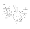
- FIG. 2 illustrates a further possibility for conversion or adaptation of a support roller winding device 2 for the realization of different winding positions.
- the basic structure corresponds to that in FIG. 1a
- the central support roller 8 in these directions can be changed in position, so that all theoretical possible winding positions for both winding stations 4, 5 are adjustable by the individual combination options despite stationary arrangement of the other first winding station 4.
- the mobility of the support roller 8 relative to the stationary, on the one hand the crest line of the support roller 8 arranged winding station 4 is carried out to the effect that this can assume a winding position, which may correspond to any theoretically possible position on the outer circumference 13 of the support roller 8.
- the support roller 8 is thus movable relative to the guide head 11 of the first winding station 4 in the vertical direction such that always a winding nip 19 is formed. This means that the winding carried on the guide head 11 or 12 contacted in each theoretically and technologically meaningful position with its outer periphery of the outer periphery 13 of the support roller.
- any positioning which makes it possible for the roll 6, 7 to rest on or abut the outer circumference 13 of the support roll is conceivable.
- the position of the second winding station, here the winding station 5, is then freely adjustable relative to the outer circumference 13 of the central support roller 8, whereby again all theoretically possible and technologically meaningful positions of the guide head 12 relative to the support roller 8, in particular the outer periphery 13 of the support roller. 8 should be feasible.
- the adjustment paths in the axial and vertical directions here with a 5 and a 8 for the axial direction and v 5 and v 8 reproduced for the vertical direction to provide.
- the individual device can be limited in terms of the theoretically possible travel paths to the individual actuating devices, here for example the adjusting device 16 for the central support roller and / or the adjusting device 17 for the winding station 4.
- the adjusting devices 16 and 17 are indicated only schematically and with regard to the functional coupling to the support roller 8 and the winding stations 4, 5 shown.
- the structural design can be implemented in various ways.
- these combined with adjustment in the axial, that is machine direction and / or vertical direction preferably comprise guide means mounted one inside the other, in the simplest case of sliding guides 21, 22 in which the bearings are displaced via adjusting elements.
- the storage or suspension of the individual winding stations 4 and 5 and / or the central support roller 8 can be done either in the vertical direction in the area of the machine base or foundation or as in the FIGS. 1a and 1b illustrated on a vertically upwardly arranged traverse 18.
- the concrete selection depends on the individual requirements of the application and the specific further configuration of slitter 3, in which the back-up roll winding device 2 according to the invention is integrated.
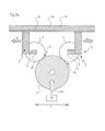
- FIGS. 3a and 3b illustrate a particularly advantageous embodiment, with which different winding concepts already known Stützwalzenwickelvorraumen can be realized in a simple manner.
- the back-up roll winding device 2 here also comprises at least two winding stations 4 and 5, which are positioned opposite a central support roll 8 and thus describe the winding positions in the individual winding stations 4 and 5 for the individual individual webs F1, F2 of a fibrous web F.
- the support elements 9, 10 the arrangement and storage of the guide heads 11, 12 and the formation of the winding nips 10, 20
- the same reference numbers are therefore used here for the same elements.
- the individual winding positions from a combination of the adjustability of the central support roller 8 and the individual winding stations 4 and 5 are realized.
- the vertical adjustment component of the support roller 8 is assigned, while the axial adjustment component is assigned to the individual winding stations 4 and 5.
- the central support roller 8 only one adjustment, and not as in the FIG. 2 in both directions, here is the central support roller 8 only displaced in the vertical direction, while the two central winding stations 4 and 5 in the horizontal direction, that is viewed in the axial direction or in the machine direction, are changeable in their position.
- FIG. 3a illustrates an embodiment of a support roller winding device 2 with the two winding stations 4 and 5 in a first operating position I, which corresponds to the first winding station 4 of the 1 o'clock position, while this corresponds to the winding station 5 of the 11 o'clock position.
- Both winding stations 4 and 5 are here exemplarily on a guide device 14, which is formed by a running in the machine direction carrier part of a frame or frame of the device 1, in particular a cross member 18, wherein the bearing axially parallel to the bearing axis L 8 of the support roller 8 takes place.
- the storage of the winding stations 4 and 5 takes place here slidably, for example in a guide device 14, which acts as a sliding guide or roller bearing guide 21.
- the central support roller 8 is movable here in the vertical direction, while this is stationary in the axial direction with respect to their position. This makes it possible, the arrangement of the winding nips 19, 20 on the support roller 8, in particular the outer circumference 13, make symmetrical according to the requirements of the individual case and a change also in a symmetrical manner with respect to the apex line, which is arranged perpendicular to the longitudinal axis L 8 of the support roller 8 is to change.
- the support roller 8 can be influenced in its position in the vertical direction via the adjusting device 16. With regard to the design of the adjusting device 16, there are a large number of options which can be selected depending on the application requirements.
- the FIG. 3a illustrates a first functional position I of the individual winding stations 4 and 5.
- the FIG. 3b illustrates an embodiment after adjustment of the winding stations 4 and 5 in the horizontal direction and the central support roller 8 in the vertical direction.
- the central support roller 8 has in the case shown, for example, at least one adjustment v 8 , which corresponds approximately to the size of the radius of the central support roller 8, preferably the Truverstellweg v 8 , that is, starting from a position, the sum of the theoretical Einzelverstellwege in both directions in the vertical direction in the range of 0 to 0.8 of the diameter D of the support roller 8, most preferably in the range of 0.2 to 0.7 x D, most preferably 0.3 to 0.5 x D.
- the drive is either itself with traversable or it is depending on the size of the travel means, such as different gear ratios provided over the compensation can take place, these can be engaged or interchangeable depending on Umrüsthari.
- the change in position takes place in such a way that the axis parallelism between the central support roller 8, in particular the bearing axis L 8 and those of the winding rolls 7, 8 in the individual winding stations 4, 5 is given in all functional states.
- the adjustability can be carried out continuously or stepwise.
- the adjustment possibilities according to the invention are merely exemplary.
- the structural design and implementation itself can be varied. The individual options will not be discussed in detail here.
- the adjusting devices can be driven and operated purely mechanically, electro-hydraulically, electropneumatically.
Landscapes
- Winding Of Webs (AREA)
- Replacement Of Web Rolls (AREA)
Applications Claiming Priority (1)
| Application Number | Priority Date | Filing Date | Title |
|---|---|---|---|
| DE102007025804A DE102007025804A1 (de) | 2007-06-02 | 2007-06-02 | Wickelvorrichtung |
Publications (2)
| Publication Number | Publication Date |
|---|---|
| EP1997756A2 true EP1997756A2 (fr) | 2008-12-03 |
| EP1997756A3 EP1997756A3 (fr) | 2009-05-06 |
Family
ID=39712315
Family Applications (1)
| Application Number | Title | Priority Date | Filing Date |
|---|---|---|---|
| EP08151875A Withdrawn EP1997756A3 (fr) | 2007-06-02 | 2008-02-25 | Dispositif d'enroulement |
Country Status (2)
| Country | Link |
|---|---|
| EP (1) | EP1997756A3 (fr) |
| DE (1) | DE102007025804A1 (fr) |
Cited By (1)
| Publication number | Priority date | Publication date | Assignee | Title |
|---|---|---|---|---|
| CN120383201A (zh) * | 2025-06-30 | 2025-07-29 | 泉州维林森体育用品有限公司 | 一种高弹性纺织面料收卷装置及工艺 |
Citations (1)
| Publication number | Priority date | Publication date | Assignee | Title |
|---|---|---|---|---|
| DE4424848A1 (de) | 1994-07-14 | 1996-01-18 | Jagenberg Papiertech Gmbh | Wickelmaschine zum Aufwickeln von Materialbahnen, insbesondere Papier- oder Kartonbahnen |
Family Cites Families (16)
| Publication number | Priority date | Publication date | Assignee | Title |
|---|---|---|---|---|
| US3123315A (en) * | 1964-03-03 | Cutting sheets of web material | ||
| NL278449A (fr) * | 1961-05-15 | |||
| DE1574307B2 (de) * | 1964-08-02 | 1973-07-26 | Hermann Berstorff Maschinenbau GmbH 3000 Hannover | Vorrichtung zum fortlaufenden aufwickeln einer folienbahn auf wickelhuelsen |
| DE6806232U (de) * | 1968-11-08 | 1969-03-13 | Monforts Fa A | Einwalzen-steigdockenabrollung |
| DE2109158A1 (de) * | 1971-02-26 | 1972-09-07 | Goebel Gmbh Maschf | Rollenschneid und Wickelmaschine mit Einzelaufwicklung der Streifen |
| DE3541906C1 (de) * | 1985-11-27 | 1987-02-26 | Voith Gmbh J M | Wickelmaschine zum Aufwickeln einer Iaengsgeteilten Bahn |
| DE3832601C1 (en) * | 1988-09-26 | 1989-12-07 | J.M. Voith Gmbh, 7920 Heidenheim, De | Winding machine for web-like material, especially paper |
| WO1996037429A1 (fr) * | 1995-05-24 | 1996-11-28 | Voith Sulzer Papiermaschinen Gmbh | Dispositif d'enroulement pour renvider une bande de papier |
| US5931406A (en) * | 1997-12-08 | 1999-08-03 | Voith Sulzer Papiertechnik Patent Gmbh | Method and winder for the continuous winding of a material web |
| FI104161B (fi) * | 1998-02-17 | 1999-11-30 | Valmet Corp | Menetelmä ja laitteisto rainan rullauksessa |
| DE19851023B4 (de) * | 1998-11-05 | 2005-11-03 | Stora Enso Publication Paper Ag | Rollenwickeleinrichtung |
| US6264130B1 (en) * | 1999-09-13 | 2001-07-24 | Faustel, Inc. | Duplex web roll winding and splicing apparatus |
| EP1375401B1 (fr) * | 2002-06-25 | 2007-01-03 | A. CELLI NONWOVENS S.p.A. | Ré-enrouleuse avec des cylindres auxiliaires et méthode d'enroulement associée |
| DE102004020322A1 (de) * | 2004-04-26 | 2005-11-10 | Voith Paper Patent Gmbh | Wickelmaschine zum kontinuierlichen Aufwickeln einer Materialbahn |
| DE102004054987A1 (de) * | 2004-11-13 | 2006-05-18 | Voith Paper Patent Gmbh | Rollenwickelvorrichtung und Verfahren zum Erzeugen von Wickelrollen |
| DE102005000180A1 (de) * | 2005-12-12 | 2007-06-14 | Voith Patent Gmbh | Leit- oder Kontaktwalzenanordnung zum Handhaben einer Materialbahn |
-
2007
- 2007-06-02 DE DE102007025804A patent/DE102007025804A1/de not_active Withdrawn
-
2008
- 2008-02-25 EP EP08151875A patent/EP1997756A3/fr not_active Withdrawn
Patent Citations (1)
| Publication number | Priority date | Publication date | Assignee | Title |
|---|---|---|---|---|
| DE4424848A1 (de) | 1994-07-14 | 1996-01-18 | Jagenberg Papiertech Gmbh | Wickelmaschine zum Aufwickeln von Materialbahnen, insbesondere Papier- oder Kartonbahnen |
Cited By (2)
| Publication number | Priority date | Publication date | Assignee | Title |
|---|---|---|---|---|
| CN120383201A (zh) * | 2025-06-30 | 2025-07-29 | 泉州维林森体育用品有限公司 | 一种高弹性纺织面料收卷装置及工艺 |
| CN120383201B (zh) * | 2025-06-30 | 2025-09-09 | 泉州维林森体育用品有限公司 | 一种高弹性纺织面料收卷装置及工艺 |
Also Published As
| Publication number | Publication date |
|---|---|
| EP1997756A3 (fr) | 2009-05-06 |
| DE102007025804A1 (de) | 2008-12-04 |
Similar Documents
| Publication | Publication Date | Title |
|---|---|---|
| EP0912435B1 (fr) | Procede de bobinage continu d'une bande de materiau et bobineuse correspondante | |
| AT505818B1 (de) | Verfahren und anordnung bei einer abrollvorrichtung für eine faserbahn | |
| EP0855355A2 (fr) | Machine d'enroulement et procédé pour l'enroulement continu d'un bande de matériel | |
| EP0921085A2 (fr) | Procédé et machine d'enroulage pour enrouler en continu une bande de matière | |
| DE1574301A1 (de) | Aufrollmaschine fuer Papier oder dergleichen,insbesondere Rollenschneid- und Umrollmaschine | |
| DE60217314T2 (de) | Umwickelmaschine mit Hilfszylindern und dazugehöriges Wickelverfahren | |
| EP0887294B1 (fr) | Machine à bobiner | |
| EP0450311A1 (fr) | Enrouleur pour feuilles continues | |
| AT509652B1 (de) | Aufroller und verfahren zum aufrollen einer faserbahn | |
| EP0916603B1 (fr) | Machine et méthode de bobinage, particulièrement pour une refendeuse | |
| AT506493B1 (de) | Verfahren zum aufrollen einer papier- oder kartonbahn, und rollapparat | |
| DE19735590A1 (de) | Wickelmaschine zum Aufwickeln einer Materialbahn | |
| EP1238933A1 (fr) | Méthode et dispositif pour continuellement enrouler une bande de matériau | |
| DE69403148T2 (de) | Wickelmaschine für bandförmiges Material | |
| DE69709173T2 (de) | Belastungswalzenanordnüng. | |
| EP0942889B1 (fr) | Bobineuse pour enrouler une bande de materiau, notamment une bande de papier ou de carton pour former un rouleau bobine | |
| DE102007025804A1 (de) | Wickelvorrichtung | |
| DE102011116308A1 (de) | Doppeltragwalzenroller | |
| EP0918033B1 (fr) | Dispositif et procédé de bobinage pour l'enroulement de bandes de matériau | |
| EP0999159B1 (fr) | Dispositif de bobinage | |
| DE69909083T2 (de) | Verfahren zum wickeln einer papier- oder kartonbahn und wickler für eine papier- oder kartonbahn | |
| EP1657194B1 (fr) | Dispositif d'enroulage de bobines et procédé pour l'enroulement de bobines | |
| AT509265B1 (de) | Wickelpartie für einen rollenschneider einer faserbahn und verfahren zum modernisieren einer wickelpartie für einen rollenschneider einer faserbahn | |
| DE102008053467A1 (de) | Mit einem Druckwalzenbalken und einer Druckwalze versehener Aufroller vom Tragwalzentyp und Verfahren | |
| EP1206403B1 (fr) | Bobineuse-refendeuse |
Legal Events
| Date | Code | Title | Description |
|---|---|---|---|
| PUAI | Public reference made under article 153(3) epc to a published international application that has entered the european phase |
Free format text: ORIGINAL CODE: 0009012 |
|
| AK | Designated contracting states |
Kind code of ref document: A2 Designated state(s): AT BE BG CH CY CZ DE DK EE ES FI FR GB GR HR HU IE IS IT LI LT LU LV MC MT NL NO PL PT RO SE SI SK TR |
|
| AX | Request for extension of the european patent |
Extension state: AL BA MK RS |
|
| PUAL | Search report despatched |
Free format text: ORIGINAL CODE: 0009013 |
|
| AK | Designated contracting states |
Kind code of ref document: A3 Designated state(s): AT BE BG CH CY CZ DE DK EE ES FI FR GB GR HR HU IE IS IT LI LT LU LV MC MT NL NO PL PT RO SE SI SK TR |
|
| AX | Request for extension of the european patent |
Extension state: AL BA MK RS |
|
| 17P | Request for examination filed |
Effective date: 20091106 |
|
| AKX | Designation fees paid |
Designated state(s): AT DE FI IT SE |
|
| R17P | Request for examination filed (corrected) |
Effective date: 20091106 |
|
| 17Q | First examination report despatched |
Effective date: 20100525 |
|
| RIC1 | Information provided on ipc code assigned before grant |
Ipc: B65H 18/26 20060101ALI20130117BHEP Ipc: B65H 18/02 20060101AFI20130117BHEP |
|
| GRAP | Despatch of communication of intention to grant a patent |
Free format text: ORIGINAL CODE: EPIDOSNIGR1 |
|
| INTG | Intention to grant announced |
Effective date: 20130417 |
|
| STAA | Information on the status of an ep patent application or granted ep patent |
Free format text: STATUS: THE APPLICATION IS DEEMED TO BE WITHDRAWN |
|
| 18D | Application deemed to be withdrawn |
Effective date: 20130903 |