EP1997954A1 - Procédé de fonctionnement d'une unité de traitement réglée hors ligne en fonction d'une machine de fabrication de bandes de matériau - Google Patents
Procédé de fonctionnement d'une unité de traitement réglée hors ligne en fonction d'une machine de fabrication de bandes de matériau Download PDFInfo
- Publication number
- EP1997954A1 EP1997954A1 EP08155257A EP08155257A EP1997954A1 EP 1997954 A1 EP1997954 A1 EP 1997954A1 EP 08155257 A EP08155257 A EP 08155257A EP 08155257 A EP08155257 A EP 08155257A EP 1997954 A1 EP1997954 A1 EP 1997954A1
- Authority
- EP
- European Patent Office
- Prior art keywords
- processing
- machine
- lines
- processing lines
- line
- Prior art date
- Legal status (The legal status is an assumption and is not a legal conclusion. Google has not performed a legal analysis and makes no representation as to the accuracy of the status listed.)
- Granted
Links
- 238000012545 processing Methods 0.000 title claims abstract description 174
- 238000000034 method Methods 0.000 title claims abstract description 27
- 239000000463 material Substances 0.000 title claims description 25
- 238000004519 manufacturing process Methods 0.000 claims description 51
- 238000004806 packaging method and process Methods 0.000 claims description 5
- 238000012423 maintenance Methods 0.000 description 8
- 230000001105 regulatory effect Effects 0.000 description 5
- 238000010586 diagram Methods 0.000 description 3
- 230000001360 synchronised effect Effects 0.000 description 3
- 238000012432 intermediate storage Methods 0.000 description 2
- 238000012856 packing Methods 0.000 description 2
- 238000004804 winding Methods 0.000 description 2
- FGRBYDKOBBBPOI-UHFFFAOYSA-N 10,10-dioxo-2-[4-(N-phenylanilino)phenyl]thioxanthen-9-one Chemical compound O=C1c2ccccc2S(=O)(=O)c2ccc(cc12)-c1ccc(cc1)N(c1ccccc1)c1ccccc1 FGRBYDKOBBBPOI-UHFFFAOYSA-N 0.000 description 1
- 238000013459 approach Methods 0.000 description 1
- 238000003490 calendering Methods 0.000 description 1
- 230000001419 dependent effect Effects 0.000 description 1
- 238000001514 detection method Methods 0.000 description 1
- 238000009826 distribution Methods 0.000 description 1
- 238000011143 downstream manufacturing Methods 0.000 description 1
- 238000012544 monitoring process Methods 0.000 description 1
- 230000002123 temporal effect Effects 0.000 description 1
Images


Classifications
-
- D—TEXTILES; PAPER
- D21—PAPER-MAKING; PRODUCTION OF CELLULOSE
- D21F—PAPER-MAKING MACHINES; METHODS OF PRODUCING PAPER THEREON
- D21F11/00—Processes for making continuous lengths of paper, or of cardboard, or of wet web for fibre board production, on paper-making machines
-
- D—TEXTILES; PAPER
- D21—PAPER-MAKING; PRODUCTION OF CELLULOSE
- D21G—CALENDERS; ACCESSORIES FOR PAPER-MAKING MACHINES
- D21G1/00—Calenders; Smoothing apparatus
-
- D—TEXTILES; PAPER
- D21—PAPER-MAKING; PRODUCTION OF CELLULOSE
- D21G—CALENDERS; ACCESSORIES FOR PAPER-MAKING MACHINES
- D21G9/00—Other accessories for paper-making machines
- D21G9/0009—Paper-making control systems
Definitions
- the invention relates to a method for operating a, downstream of a machine for producing webs, in particular fibrous webs in the form of paper, board or tissue webs downstream processing unit with two parallel processing lines.
- Machines for the production of material webs in the form of fibrous webs are often so-called finishing units, that is subordinate processing units for surface finishing and / or division into single roles on- or offline.
- the material web production output coming from the machine for producing material webs can be further processed immediately or else offset in time in the desired manner, for example calendered and / or divided into single webs and wound up.
- a calender and a slitter-winder are arranged one after the other.
- the capacity of a calender and / or a slitter-winder is not sufficient to handle the production output of such a machine for the production of fibrous webs in a timely manner.
- two processing lines comprising at least one processing machine, in particular a slitter-winder and / or an offline calender, are arranged parallel to each other.
- One of the processing lines is arranged in series or in line with the machine for producing the material web and the second laterally offset thereto.
- the wait for both machines is positioned between the two lines, allowing for easy checking of the operation and control of a single line.
- the division takes place for example via a magazine in the form of an intermediate storage for the production output of the machine for the production of fibrous webs.
- the arbitrary division often leads to an overcapacity in the processing unit for which personnel must be provided. The provision of these overcapacities makes little economic sense.
- the machines of the individual lines also have due to the very different and strong fluctuations subject to utilization different maintenance intervals, leading to different downtime.
- the invention is therefore based on the object, a method for operating a processing unit with two processing lines, which are downstream of a machine for the production of fibrous webs to develop such that the excess capacity are reduced by non-use of assets held to a large extent and by intelligent processing management as far as possible a uniform utilization and wear of the individual machines of the two lines takes place.
- the production output of the machine is equally divided between the two processing lines.
- Both Processing lines can be charged in time synchronously with the same subset of the production output or in alternation with the same subset of the production output.
- both lines are utilized equally, so in the case of maintenance, these relate to the machines of both lines.
- the maintenance intervals of both machines are then the same.
- a further advantage of a mode of operation according to the first approach is that the individual processing lines can only be designed together with regard to the production output of the machine and thus smaller processing machines can be used within the processing lines.
- the maximum loadable subset of the production output of the web production machine is determined as a function of the capacity of the individual processing lines, the maximum capacity of the processing lines being determined by the theoretically possible maximum throughput of the processing machine with the least capacity in a processing line.
- the processing machines of both processing lines are operated with the same process parameters.
- Re-loading is to maintain a continuous operation in a predefined period of time prior to or concurrent with the completion of the passage of a subset to be processed, for which the passage of that subset of the production output through the individual processing lines is monitored.
- Non-editable subsets are fed to a sub-magazine preceding a single processing line.
- counters are set for the individual processing line, which are increased when these processing lines are re-fed, the counter reading of the two processing lines being compared and, if deviating, the processing line being loaded with the lower counter number.
- a first line is equipped in detail so that it is fully utilized in its capacity, that is 100% and, if possible, no production standstill is present. If excess capacity builds up as a result of the production of the pulp web production machine, these are dismantled via the second processing line.
- the second processing line is only used to a fraction of the first. This requires that the second line in the under-utilized areas can be subjected to maintenance without disrupting the production process.
- a major advantage of the second solution is further that both processing lines do not have to be operated with the full operating crew, but for the processing line with lower utilization and jumpers and machine operators can be used part-time or these persons can be used in the meantime on other machines.
- the first solution thus requires a continuous continuous uniform utilization, while the second quasi includes a uniform utilization over a longer period of time when the utilization of the capacities between both processing lines changes.
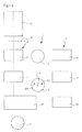
- FIG. 1a illustrates in a schematic highly simplified representation of the known assignment of a processing unit 1 to a machine 2 for the production of material webs, in particular fibrous webs in the form of paper, cardboard or tissue webs.
- the processing unit 1 is the machine 2 functionally and spatially downstream.
- the assignment is made offline, ie, the processing unit 1 is not integrated in the machine 2, but downstream of this as a separate functional unit, so that the fibrous web produced in the machine 2 is not transferred directly into this but spatially and temporally separated from the machine 2 further processed can.
- the fibrous web is wound at the end of the machine 2 to a web roll 20.
- the number of such material web rolls based on a predefined time unit determines the production output of the machine 2. This is fed via an intermediate storage in the form of a magazine 9 of the processing unit 1.
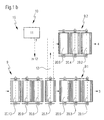
- the magazine 9 is schematically simplified in much FIG. 1b shown.
- the processing unit 1 comprises two processing lines 3 and 4 with at least one respective processing machine for the material web, which are arranged parallel to one another and are preferably characterized by the same structure and / or the same production capacity.
- Production capacity is understood to mean the amount of production output possible per unit of time.
- the production output of a processing line 3 or 4 corresponds to the final finished product after passing through one of the processing lines 3 or 4.
- One of the two processing lines 3 is arranged downstream of the machine 2, while the second processing line 4 parallel thereto, that is preferably laterally offset, is arranged.
- the individual processing lines 3, 4 each comprise at least one, preferably a plurality of processing machines connected in series, for example a calender 5 or 6 respectively and a downstream slitter 7 or 8.
- the total capacity of a processing unit 1 corresponds to 1.2 to 1.8 times, preferably 1.3 to 1.5 times the production capacity of the machine 2 for producing a material web.
- both processing lines 3, 4 are designed for this purpose preferably with regard to the dimensioning and the process parameters when operating the individual processing machines such that the same production capacity is given in both processing lines 3,4. This depends on the processing machine of a processing line 3, 4, which is characterized by the lowest flow rate or the lowest production output per unit time. According to a particularly advantageous embodiment, both processing lines 3, 4 are constructed identically. However, this is not mandatory. Both processing lines 3, 4 are preferably also operated with the same operating parameters for this purpose.
- a uniform feed of the individual processing lines 3, 4 can according to FIG. 2a synchronous with time or according to FIG. 2b with temporal offset to each other. This is dependent, for example, on the capacity of a processing line 3, 4 and thus of the entire processing unit 1 in relation to the total output of the machine 2. Timing is synchronized preferably when the total capacity of the processing unit 1 is very small, ie only slightly exceeds the production output , Processing lines 3, 4 are preferably fed alternately alternately at high production output.
- the allocating device 16 comprises a control and / or regulating device 10 which is controlled via a control system. and / or control device 11 controls the processes.
- control and / or regulating device is the entirety of detection devices, actuators and the control and / or regulating device 11, which in Generally available as a control unit, understood.
- at least one manipulated variable Y is generated, which controls an adjusting device 12 of the allocating device 16, via which the respective material web roll 20.1 to 20.n from the magazine 9 one of the two lines 3 or 4 is supplied, here the sub-magazines 9.1 and 9.2.
- a continuous, alternating loading of the individual processing lines 3, 4 is in the simplest case in the control an increase of a counter Z made for each of the processing lines 3 and 4, wherein at counter equals always one of the processing lines, here by way of example the processing line 3 with respect to the loading Has priority.
- a method is exemplary in the FIG. 2b explained with reference to a signal flow diagram.
- one of the processing lines 3 or 4 is charged with a partial quantity of the production output P2 of the machine 2, which may correspond to at least one material web roll 20.
- the time is offset to the second processing line 4 or 3 charged with the same subset.
- the processing in particular the passage of a respective sub-set located in the processing line and passing through it, is monitored and, after passing through the processing line 3, 4 or temporally before the completion of the processing line 3, 4, it is again allocated a subset.
- the count Z1, Z2 in the presence of material web rolls 20.1 to 20.n and the required assignment of a roll to a processing line 3, 4, it is checked how high the count Z1, Z2 is for the individual processing lines 3 and 4.
- Z1 corresponds to a count n 1
- Z 2 corresponds to a count of n 2 .
- both processing lines 3, 4 are utilized evenly. This means that for each of the lines, a full-time operator's crew of machine operators and at least one other person is required. In this case, the machines are evenly worn in a corresponding manner, in particular in further processing the same web rolls, so that the maintenance intervals are evenly distributed.
- a second possible embodiment provides for one of the processing lines, for example, to fully utilize the first processing line 3 and to use the second processing line 4 only for overcapacities or vice versa.
- the processing lines 3 and 4 are preferably designed such that they can accommodate a large part of the production output of the machine 2. It can thereby be achieved that, in the case of an overcapacity, one of the two processing lines 3 or 4, here by way of example 4, is only weakly utilized, while the other, for example 3, continuously produces with predefined maximum throughput which can correspond to the theoretically possible maximum throughput. It is determined on the basis of the available available capacity of the first processing line 3, at which intervals the supply of the web rolls 20 must be made to line 3.
- Such quantities can be, for example, the passage speed V passage of the material web through the processing line 3, the winding size and the type of material. If the throughput speed is the same as that on the machine 2, theoretically the entire production P2 can be further processed via the first processing line 3. However, since this is not usually the case and there is a deviation between P2 and the possible production P3 in the processing line 3, a full load of the first processing line 3 is always selected depending on the capacity, the full load corresponds to a time and quantity feed which is to be handled by the first processing line 3 and which utilizes 100% of the available capacity. This means that the processing line 3 is continuously assigned to operating personnel, at least one machine operator M3. Only the remainder x, ie, the material webs 20.
- N that can not be processed by the first processing line 3 are further processed via the second processing line 4.
- a comparison is made between P2 and P3 and the processing lines 3 and 4 are loaded as a function of this.
- the output of the individual lines 3 and 4, the operation of the less heavily used processing line, here the processing line 4 can be taken over by jumpers S, for example, a part-time jumper.
- the operating personnel, in particular the machine operator M4 can also incidentally take on other tasks, for example, as a jumper in the remaining time of non-utilization, which is then 50%, at the waiting 15 of the processing line 3 downstream packing machine 17 act.
- Another significant advantage of partial utilization is that times of standstill of the machines are freely selectable, which can be used for maintenance.
- skillful replacement of the utilization of the two processing lines 3, 4, for example, in predefined time intervals the production can be continued continuously over very long periods, the maintenance intervals are always moved to the underutilized times.
- the function assignment between the first and second processing line can be interchanged, so that time is also gained here for maintenance work through unused capacities.
- the FIG. 1 Further clarifies the waiting 13 and 14 and 15 for the individual machines of the processing lines 3 and 4, in particular a first waiting 13 for the calender 5, 6, a second waiting 14 for the slitter 7, 8 and a third waiting 15 for the packing machine 17th , Wherein the waiting for the slitter 7 and 8 and the waiting 13 for the calender 5 and 6 between the two lines 3, 4 is arranged.
- the effort for the operator can be significantly reduced.
- the loading of the first processing line for uninterrupted operation and thus 100% utilization is carried out in such a way that the material webs of the processing line 3 are fed virtually continuously, which are further processed here by the calender and a slitter rewinder.
- a corresponding number of material webs must always be provided in the magazine 9, which are fed to the first processing line 3. The number is determined by the output P2 of the machine 2 and the passage speed through the processing line 3.
- One of the two processing lines preferably the higher-utilization processing line, here line 3, is followed by a packaging machine 17 which serves to package the lines processing in the processing line.
- This packaging machine 17 is also used by the second processing line 4.
- the packaging machine 17 usually operates discontinuously.
- a roller doctor unit 18 is to be provided in the processing unit.
Landscapes
- Paper (AREA)
- Replacement Of Web Rolls (AREA)
- Preliminary Treatment Of Fibers (AREA)
Applications Claiming Priority (1)
| Application Number | Priority Date | Filing Date | Title |
|---|---|---|---|
| DE102007025374A DE102007025374A1 (de) | 2007-05-31 | 2007-05-31 | Verfahren zum Betreiben einer, einer Maschine zur Herstellung von Materialbahnen offline-nachgeordneten Verarbeitungseinheit |
Publications (2)
| Publication Number | Publication Date |
|---|---|
| EP1997954A1 true EP1997954A1 (fr) | 2008-12-03 |
| EP1997954B1 EP1997954B1 (fr) | 2011-11-30 |
Family
ID=39720614
Family Applications (1)
| Application Number | Title | Priority Date | Filing Date |
|---|---|---|---|
| EP08155257A Not-in-force EP1997954B1 (fr) | 2007-05-31 | 2008-04-28 | Procédé de fonctionnement d'une unité de traitement réglée hors ligne en fonction d'une machine de fabrication de bandes de matériau |
Country Status (3)
| Country | Link |
|---|---|
| EP (1) | EP1997954B1 (fr) |
| AT (1) | ATE535644T1 (fr) |
| DE (1) | DE102007025374A1 (fr) |
Citations (3)
| Publication number | Priority date | Publication date | Assignee | Title |
|---|---|---|---|---|
| EP1008690A2 (fr) * | 1998-12-07 | 2000-06-14 | Voith Sulzer Papiertechnik Patent GmbH | Procédé et dispositif pour la fabrication d' une bande de papier |
| WO2001065005A1 (fr) * | 2000-03-03 | 2001-09-07 | Metso Paper, Inc. | Procede et dispositif de traitement de large bande de papier ou de carton |
| DE102004039913A1 (de) | 2003-08-22 | 2005-03-17 | Metso Paper, Inc. | Verfahren zur Herstellung einer Papierbahn und eine Papiermaschinenlinie |
-
2007
- 2007-05-31 DE DE102007025374A patent/DE102007025374A1/de not_active Withdrawn
-
2008
- 2008-04-28 AT AT08155257T patent/ATE535644T1/de active
- 2008-04-28 EP EP08155257A patent/EP1997954B1/fr not_active Not-in-force
Patent Citations (3)
| Publication number | Priority date | Publication date | Assignee | Title |
|---|---|---|---|---|
| EP1008690A2 (fr) * | 1998-12-07 | 2000-06-14 | Voith Sulzer Papiertechnik Patent GmbH | Procédé et dispositif pour la fabrication d' une bande de papier |
| WO2001065005A1 (fr) * | 2000-03-03 | 2001-09-07 | Metso Paper, Inc. | Procede et dispositif de traitement de large bande de papier ou de carton |
| DE102004039913A1 (de) | 2003-08-22 | 2005-03-17 | Metso Paper, Inc. | Verfahren zur Herstellung einer Papierbahn und eine Papiermaschinenlinie |
Also Published As
| Publication number | Publication date |
|---|---|
| ATE535644T1 (de) | 2011-12-15 |
| EP1997954B1 (fr) | 2011-11-30 |
| DE102007025374A1 (de) | 2008-12-04 |
Similar Documents
| Publication | Publication Date | Title |
|---|---|---|
| EP0311831B1 (fr) | Régulation des étapes d'ouverture de fibres d'une installation de préparation à la filature | |
| EP3144418A1 (fr) | Procede d'adaptation d'une conception usine concernant une fabrication de lot de fil d'un metier a tisser a rotor a extremite ouverte | |
| EP3412804A1 (fr) | Procede et dispositif de commande de production dans un battage | |
| DE19852257A1 (de) | Wickelmaschine zum Aufwickeln einer Materialbahn | |
| EP3463710B1 (fr) | Dresseuse | |
| EP1997954B1 (fr) | Procédé de fonctionnement d'une unité de traitement réglée hors ligne en fonction d'une machine de fabrication de bandes de matériau | |
| EP1542919A2 (fr) | Procede et dispositif de regulation de la tension d'une bande de systeme a bandes multiples | |
| EP3129312A1 (fr) | Dispositif et procédé d'alimentation de bandes de matériau dans un équipement de transformation | |
| EP3794169B1 (fr) | Procédé de détermination du niveau de remplissage du tambour d'une carde et carde équipée d'une unité de commande associée | |
| DE102009001171A1 (de) | Anordnung von Rollenschneideinrichtung und Verfahren zum Betreiben einer Anordnung von Rollenschneideinrichtung | |
| DE2413956C2 (de) | Getreidemahlverfahren | |
| EP0329602A2 (fr) | Procédé et dispositif pour emmagasiner et convertir des produits plats de préférence arrivant dans une formation en écailles | |
| DE102010002703A1 (de) | Anordnung und Verfahren zur Regelung einer Kraft in einem Spalt zwischen zwei Walzen | |
| EP2946927B1 (fr) | Procédé de commande d'une presse d'impression | |
| EP3936955B1 (fr) | Chaîne d'emballage d'une ligne d'emballage ainsi que procédé de fonctionnement d'une telle chaîne d'emballage | |
| EP3425092B1 (fr) | Dispositif et procédé pour etaler un faisceau de fibres | |
| DE19849375A1 (de) | Verfahren zum Einstellen des Werkstückflusses | |
| DE102015117938A1 (de) | Verfahren zum Austauschen von Unterriemchen eines Streckwerkes einer Spinnmaschine und Spinnmaschine | |
| EP1741554B1 (fr) | Procédé de fonctionnement d'une machine à imprimer | |
| DE19720174B4 (de) | Kalander | |
| EP2151386A1 (fr) | Procédé d'optimisation du mode de fonctionnement de dispositifs d'emballage de rouleaux de bandes de matériaux et système d'équipement pour consommables | |
| WO2011069573A1 (fr) | Installation pour fabriquer et traiter des piles de feuilles, en particulier des piles de feuilles de papier | |
| EP3467199A1 (fr) | Dispositif de fabrication et procédé de fabrication pour papier de sécurité | |
| EP1615773A2 (fr) | Procede permettant de generer un produit d'impression, dispositif de post-traitement, et systeme servant a generer des produits d'impression | |
| DE102023211806A1 (de) | Verfahren zum Betreiben einer Rollenrichtmaschine für metallisches Gut |
Legal Events
| Date | Code | Title | Description |
|---|---|---|---|
| PUAI | Public reference made under article 153(3) epc to a published international application that has entered the european phase |
Free format text: ORIGINAL CODE: 0009012 |
|
| AK | Designated contracting states |
Kind code of ref document: A1 Designated state(s): AT BE BG CH CY CZ DE DK EE ES FI FR GB GR HR HU IE IS IT LI LT LU LV MC MT NL NO PL PT RO SE SI SK TR |
|
| AX | Request for extension of the european patent |
Extension state: AL BA MK RS |
|
| 17P | Request for examination filed |
Effective date: 20090603 |
|
| 17Q | First examination report despatched |
Effective date: 20090624 |
|
| AKX | Designation fees paid |
Designated state(s): AT DE FI IT SE |
|
| GRAP | Despatch of communication of intention to grant a patent |
Free format text: ORIGINAL CODE: EPIDOSNIGR1 |
|
| GRAS | Grant fee paid |
Free format text: ORIGINAL CODE: EPIDOSNIGR3 |
|
| GRAA | (expected) grant |
Free format text: ORIGINAL CODE: 0009210 |
|
| AK | Designated contracting states |
Kind code of ref document: B1 Designated state(s): AT DE FI IT SE |
|
| REG | Reference to a national code |
Ref country code: DE Ref legal event code: R096 Ref document number: 502008005731 Country of ref document: DE Effective date: 20120126 |
|
| REG | Reference to a national code |
Ref country code: SE Ref legal event code: TRGR |
|
| PGFP | Annual fee paid to national office [announced via postgrant information from national office to epo] |
Ref country code: DE Payment date: 20120420 Year of fee payment: 5 |
|
| PGFP | Annual fee paid to national office [announced via postgrant information from national office to epo] |
Ref country code: FI Payment date: 20120411 Year of fee payment: 5 |
|
| PGFP | Annual fee paid to national office [announced via postgrant information from national office to epo] |
Ref country code: IT Payment date: 20120420 Year of fee payment: 5 |
|
| PLBE | No opposition filed within time limit |
Free format text: ORIGINAL CODE: 0009261 |
|
| STAA | Information on the status of an ep patent application or granted ep patent |
Free format text: STATUS: NO OPPOSITION FILED WITHIN TIME LIMIT |
|
| 26N | No opposition filed |
Effective date: 20120831 |
|
| REG | Reference to a national code |
Ref country code: SE Ref legal event code: EUG |
|
| REG | Reference to a national code |
Ref country code: DE Ref legal event code: R097 Ref document number: 502008005731 Country of ref document: DE Effective date: 20120831 |
|
| PG25 | Lapsed in a contracting state [announced via postgrant information from national office to epo] |
Ref country code: SE Free format text: LAPSE BECAUSE OF NON-PAYMENT OF DUE FEES Effective date: 20120429 |
|
| PG25 | Lapsed in a contracting state [announced via postgrant information from national office to epo] |
Ref country code: DE Free format text: LAPSE BECAUSE OF NON-PAYMENT OF DUE FEES Effective date: 20131101 |
|
| REG | Reference to a national code |
Ref country code: DE Ref legal event code: R119 Ref document number: 502008005731 Country of ref document: DE Effective date: 20131101 |
|
| PG25 | Lapsed in a contracting state [announced via postgrant information from national office to epo] |
Ref country code: FI Free format text: LAPSE BECAUSE OF NON-PAYMENT OF DUE FEES Effective date: 20130428 Ref country code: IT Free format text: LAPSE BECAUSE OF NON-PAYMENT OF DUE FEES Effective date: 20130428 |
|
| REG | Reference to a national code |
Ref country code: AT Ref legal event code: MM01 Ref document number: 535644 Country of ref document: AT Kind code of ref document: T Effective date: 20130428 |
|
| PG25 | Lapsed in a contracting state [announced via postgrant information from national office to epo] |
Ref country code: AT Free format text: LAPSE BECAUSE OF NON-PAYMENT OF DUE FEES Effective date: 20130428 |