EP3144418A1 - Procede d'adaptation d'une conception usine concernant une fabrication de lot de fil d'un metier a tisser a rotor a extremite ouverte - Google Patents
Procede d'adaptation d'une conception usine concernant une fabrication de lot de fil d'un metier a tisser a rotor a extremite ouverte Download PDFInfo
- Publication number
- EP3144418A1 EP3144418A1 EP16184725.6A EP16184725A EP3144418A1 EP 3144418 A1 EP3144418 A1 EP 3144418A1 EP 16184725 A EP16184725 A EP 16184725A EP 3144418 A1 EP3144418 A1 EP 3144418A1
- Authority
- EP
- European Patent Office
- Prior art keywords
- routine
- workstations
- control
- yarn
- group
- Prior art date
- Legal status (The legal status is an assumption and is not a legal conclusion. Google has not performed a legal analysis and makes no representation as to the accuracy of the status listed.)
- Granted
Links
Images



Classifications
-
- D—TEXTILES; PAPER
- D01—NATURAL OR MAN-MADE THREADS OR FIBRES; SPINNING
- D01H—SPINNING OR TWISTING
- D01H4/00—Open-end spinning machines or arrangements for imparting twist to independently moving fibres separated from slivers; Piecing arrangements therefor; Covering endless core threads with fibres by open-end spinning techniques
- D01H4/42—Control of driving or stopping
-
- D—TEXTILES; PAPER
- D01—NATURAL OR MAN-MADE THREADS OR FIBRES; SPINNING
- D01H—SPINNING OR TWISTING
- D01H13/00—Other common constructional features, details or accessories
- D01H13/32—Counting, measuring, recording or registering devices
-
- B—PERFORMING OPERATIONS; TRANSPORTING
- B65—CONVEYING; PACKING; STORING; HANDLING THIN OR FILAMENTARY MATERIAL
- B65H—HANDLING THIN OR FILAMENTARY MATERIAL, e.g. SHEETS, WEBS, CABLES
- B65H63/00—Warning or safety devices, e.g. automatic fault detectors, stop-motions ; Quality control of the package
-
- D—TEXTILES; PAPER
- D01—NATURAL OR MAN-MADE THREADS OR FIBRES; SPINNING
- D01H—SPINNING OR TWISTING
- D01H1/00—Spinning or twisting machines in which the product is wound-up continuously
- D01H1/14—Details
- D01H1/20—Driving or stopping arrangements
-
- D—TEXTILES; PAPER
- D01—NATURAL OR MAN-MADE THREADS OR FIBRES; SPINNING
- D01H—SPINNING OR TWISTING
- D01H4/00—Open-end spinning machines or arrangements for imparting twist to independently moving fibres separated from slivers; Piecing arrangements therefor; Covering endless core threads with fibres by open-end spinning techniques
- D01H4/04—Open-end spinning machines or arrangements for imparting twist to independently moving fibres separated from slivers; Piecing arrangements therefor; Covering endless core threads with fibres by open-end spinning techniques imparting twist by contact of fibres with a running surface
- D01H4/08—Rotor spinning, i.e. the running surface being provided by a rotor
-
- D—TEXTILES; PAPER
- D01—NATURAL OR MAN-MADE THREADS OR FIBRES; SPINNING
- D01H—SPINNING OR TWISTING
- D01H4/00—Open-end spinning machines or arrangements for imparting twist to independently moving fibres separated from slivers; Piecing arrangements therefor; Covering endless core threads with fibres by open-end spinning techniques
- D01H4/42—Control of driving or stopping
- D01H4/44—Control of driving or stopping in rotor spinning
-
- G—PHYSICS
- G05—CONTROLLING; REGULATING
- G05B—CONTROL OR REGULATING SYSTEMS IN GENERAL; FUNCTIONAL ELEMENTS OF SUCH SYSTEMS; MONITORING OR TESTING ARRANGEMENTS FOR SUCH SYSTEMS OR ELEMENTS
- G05B19/00—Program-control systems
- G05B19/02—Program-control systems electric
- G05B19/18—Numerical control [NC], i.e. automatically operating machines, in particular machine tools, e.g. in a manufacturing environment, so as to execute positioning, movement or co-ordinated operations by means of program data in numerical form
- G05B19/409—Numerical control [NC], i.e. automatically operating machines, in particular machine tools, e.g. in a manufacturing environment, so as to execute positioning, movement or co-ordinated operations by means of program data in numerical form characterised by using manual data input [MDI] or by using control panel, e.g. controlling functions with the panel; characterised by control panel details or by setting parameters
-
- B—PERFORMING OPERATIONS; TRANSPORTING
- B65—CONVEYING; PACKING; STORING; HANDLING THIN OR FILAMENTARY MATERIAL
- B65H—HANDLING THIN OR FILAMENTARY MATERIAL, e.g. SHEETS, WEBS, CABLES
- B65H2701/00—Handled material; Storage means
- B65H2701/30—Handled filamentary material
- B65H2701/31—Textiles threads or artificial strands of filaments
-
- G—PHYSICS
- G05—CONTROLLING; REGULATING
- G05B—CONTROL OR REGULATING SYSTEMS IN GENERAL; FUNCTIONAL ELEMENTS OF SUCH SYSTEMS; MONITORING OR TESTING ARRANGEMENTS FOR SUCH SYSTEMS OR ELEMENTS
- G05B2219/00—Program-control systems
- G05B2219/30—Nc systems
- G05B2219/36—Nc in input of data, input key till input tape
- G05B2219/36513—Select out of a plurality of programs, patterns
-
- G—PHYSICS
- G05—CONTROLLING; REGULATING
- G05B—CONTROL OR REGULATING SYSTEMS IN GENERAL; FUNCTIONAL ELEMENTS OF SUCH SYSTEMS; MONITORING OR TESTING ARRANGEMENTS FOR SUCH SYSTEMS OR ELEMENTS
- G05B2219/00—Program-control systems
- G05B2219/30—Nc systems
- G05B2219/45—Nc applications
- G05B2219/45193—Yarn manufacturing
-
- Y—GENERAL TAGGING OF NEW TECHNOLOGICAL DEVELOPMENTS; GENERAL TAGGING OF CROSS-SECTIONAL TECHNOLOGIES SPANNING OVER SEVERAL SECTIONS OF THE IPC; TECHNICAL SUBJECTS COVERED BY FORMER USPC CROSS-REFERENCE ART COLLECTIONS [XRACs] AND DIGESTS
- Y02—TECHNOLOGIES OR APPLICATIONS FOR MITIGATION OR ADAPTATION AGAINST CLIMATE CHANGE
- Y02P—CLIMATE CHANGE MITIGATION TECHNOLOGIES IN THE PRODUCTION OR PROCESSING OF GOODS
- Y02P90/00—Enabling technologies with a potential contribution to greenhouse gas [GHG] emissions mitigation
- Y02P90/02—Total factory control, e.g. smart factories, flexible manufacturing systems [FMS] or integrated manufacturing systems [IMS]
Definitions
- the invention relates to a method for adjusting a yarn section manufacturing factory design in particular an open-end rotor spinning machine having a plurality of jobs each for producing a yarn and a central control unit, which is based on a readable from a memory control routine same yarn lot producing jobs with To control the same yarn lot required control data.
- Textile machines such as, for example, open-end rotor spinning machines generally consist of a plurality of workstations arranged in series next to each other for producing a yarn section.
- workstations generally each have a spinning device for producing a thread, a yarn cleaner for checking the quality of the yarn produced, a thread take-off device and a winding device for producing a cross-wound package rotatably supported in a creel.
- the spinning devices have in their spinning housing at high speed rotating spinning rotors and sliver feeders and opening rollers, the spinning rotors, opening rollers and bobbin drive rollers and yarn guides of the winder have machine-length drives and wherein the sliver feed cylinders of the sliver feeding devices are driven by a single motor.
- the spinning and winding devices By means of the spinning and winding devices, the sliver presented in a sliver can be spun into a yarn and wound up into a cross-wound bobbin.
- open-end rotor spinning machines include a central control device and a spinning machine's own vacuum system.
- each workstation may have a workstation controller.
- the spinning or winding devices are in each case in communication with the central control device and / or the workstation control device.
- the individual workstation control devices may in turn be connected via section control units to the central control device of the semi-automatic open-end rotor spinning machine.
- An open-end rotor spinning machine is for example through the document EP 1 283 288 A2 known.
- the jobs of this textile machine are each equipped with a variety of individual drives and designed so that they can resolve incidents automatically.
- the jobs in addition to a spinning mill own, single motor driven suction nozzle, among other things, individual drives for the Fadenchangier issued, the bobbin drive roller and the thread withdrawal device.
- a so-called automatic open-end rotor spinning machine in which both the working organs of the spinning device and the working members of the winding device are acted upon by machine-length drive means.
- tangential belts for driving the spinning rotors and the opening rollers and a machine-length drive shaft for loading the sliver feed cylinders are arranged in the area of the spinning devices, wherein the associated drives are installed in a machine frame arranged on the machine frame.
- the bobbin drive rollers are arranged on machine-length bobbin drive shafts and set the traversing yarn guide on a reciprocating yarn guide rod, which are connected to a machine end side arranged traverse gear.
- thread take-off devices are available whose driven take-off rolls are also part of a machine-length drive shaft.
- the workstations of an automatic open-end rotor spinning machine are serviced by service units which, for example, patrol along the workplaces and intervene automatically if an accident has occurred at one of the workplaces.
- the present invention seeks to provide greater flexibility for textile machines, in particular open-end rotor spinning machines, with a view to a feasible with simple and inexpensive means change a yarn lot production concerned factory design.
- This object is achieved by a method for adapting a yarn section production factory design of a textile machine, in particular an open-end rotor spinning machine, having the features of claim 1.
- the textile machine has a plurality of workstations and a central control device, wherein each workstation designed for producing a yarn lot and the central control device is set to control based on a callable from a memory control routine the same yarn lot producing jobs with required for producing the same yarn lot control data.
- the proposed method comprises a step of creating a selection of drive routines, which are at least a first to third A control routine includes that enable a mutually different control of the workstations by the central control device for producing a yarn lot.
- the first control routine is designed to control all workstations with control data for producing a first yarn section.
- the first control routine When driving the workstations with control data according to the first control routine, a same yarn section is produced across all producing workstations of the textile machine. The jobs are thereby assigned to a single common group.
- the first activation routine is advantageous for a factory design of a textile machine, by means of which only one identical yarn section is to be produced. Such a control routine can be easily built on the software side without complex links or algorithms.
- the second control routine is designed to control a first group of workstations with control data for producing a first yarn section and a second group of workstations with control data for producing a second yarn section.
- the workstations of the textile machine are divided accordingly into two groups for parallel production of different yarn lots. Accordingly, the tax data differs for the different groups of jobs.
- the second control routine is advantageous for a design of a textile machine, in particular an open-end rotor spinning machine, by means of which two different yarn lots are to be produced.
- Such a control routine continues to have a simple structure and, in comparison with the first control routine, has additional links or algorithms for actuating two workstations combined in groups.
- the third drive routine is designed to respectively control a number of workstations to be set in number with control data corresponding to a yarn lot associated with the respective group, the number of groups to be determined exceeding two.
- the third control routine more than two groups of workstations can be controlled, thereby enabling a parallel production of more than two yarn lots with the open-end rotor spinning device.
- the jobs can also be assigned freely to one of the groups to be specified in number. As a result, a high variability and flexibility with regard to the different yarn lots to be produced jobs can be guaranteed.
- the method further comprises a step subsequent to the step of establishing activating a previously stored drive routine selected from the created selection of drive routines.
- the activation routine to be activated can be stored in a memory associated with the textile machine. Alternatively or additionally, the activation routine may be stored on a mobile storage medium such as, for example, a CD / DVD-ROM, a memory stick, an SD card, a cable or wirelessly connectable external memory or the like which is readable by the textile machine can be coupled.
- the jobs are assigned to a group to be controlled based on the activated control routine.
- the jobs of the open-end rotor spinning device are thus detected in groups, taking into account the activated or selected activation routine.
- the respective groups of workstations with correspondingly assigned control data are actuated by the central control device based on the activated actuation routine.
- the central control device transmits the control data required for producing a specific yarn section in accordance with the specification by the control routine to the workstations of a group which is intended for producing the assigned, specific yarn section.
- a factory-designed textile machine in particular an open-end rotor spinning machine, when changing the customer-specific requirement, only select the control routine that satisfies the new customer-specific requirement from a selection of control routines and activate it on the textile machine
- the textile machine in particular the open-end rotor spinning machine, should preferably be factory-equipped with workstations, by means of which independently different yarn lots can be produced.
- a textile machine in particular an open-end rotor spinning machine, can be provided whose factory-specific design directed to a predetermined number of different yarn lots can be simply and inexpensively changed by simply modifying and activating a corresponding control routine from the created selection of control routines to one the original interpretation different design is changeable. This can effectively shorten a customer's production downtime.
- the relevant control data which are required in each case for producing a defined yarn section, may be, for example, one or more parameters such as the rotor speed, the rotation, the crossing angle of the yarn to be wound, the bobbin stroke, the cleaning limit, the piecing setting, the bobbin diameter to be achieved which are the wound yarn length to be achieved on the cross-wound bobbin, the speed of the sliver draw-in cylinders, or similar parameters affecting the yarn.
- a change in all of these parameters affects the property of the yarn to be produced.
- another yarn or a different yarn section can already be produced at a workstation by changing only one parameter.
- the method comprises a step of blocking a possible selection of non-activated activation routines for an operator of the textile machine, in particular the open-end rotor spinning machine.
- the step of blocking may preferably take place simultaneously with or after the activating step.
- the possible selection of the non-activated control routines is electronically blocked, for example deactivated, wherein a deactivation of the lock further preferably requires electronic activation, for example by means of release by a predeterminable code. This can ensure that an operator of the textile machine makes no unwanted changes in terms of factory-set design.
- the textile machine in particular the open-end rotor spinning machine, has at least two machine sides, on each of which work stations are respectively arranged for producing a yarn section.
- the second control routine is preferably designed to control a first group of workstations on a first machine side with control data for producing a first yarn section and a second group of workstations on the second machine side with control data for producing a second yarn section.
- the third control routine is designed to control a number of workstations to be specified in number per machine side with control data corresponding to a definition of a yarn section to be produced assigned to the respective group.
- the selection of the control routines comprises a fourth control routine, which is designed to control a first group of machine-side assigned workstations with control data for producing a first yarn section and a second group of workstations assigned to the remaining ones of this machine side with control data for producing a second yarn section and to control a third group of jobs associated with the other machine side with control data for producing a third yarn lot.
- the textile machine in particular the open-end rotor spinning machine, can be designed such that parallel production of two yarn lots is possible on one of the two machine sides, while on the second machine side, a different third yarn section can be produced.
- the fourth control routine thus increases from the outset the options of design options for the textile machine. As a result, subsequent time-consuming and quite expensive measures for creating and activating such a control routine can be avoided, whereby adaptation of the textile machine to such a design is less expensive to carry out.
- the method comprises an intermediate step of storing at least one further drive routine from the created selection of drive routines into the memory and subsequently an intermediate step of selecting one of the stored drive routines for driving the respective workstations, the intermediate steps being preceded by the activating step ,
- the textile machine in particular the open-end rotor spinning machine, can thereby be designed according to customer requirements at the installation site. Short-term changes to the interpretation can also be implemented immediately without increased effort.
- the method comprises a step of isolating at least one of the jobs from the drive process based on the drive routine.
- This step is preferably downstream of the step of assigning, more preferably downstream of the step of driving.
- a further yarn section can be produced on the at least one insulated workstation in which corresponding control data required for the production of the further yarn section for controlling the at least one insulated yarn section are stored as part of the insulation.
- the central control device is designed to control predetermined jobs outside the activated control routine.
- a workstation control device assigned to the isolated workstation executes the individual control.
- a plurality of isolated workstations can furthermore be controlled correspondingly alternatively or additionally preferably via an intended section control unit.
- the method comprises a step of reallocating at least one work site from the group of work stations to one of the yarn lots to a different group of work stations be controlled to produce another yarn lot.
- a production quantity of the corresponding yarn lots can be adapted according to the circumstances, without having to undertake a complete reassignment of jobs.
- the correspondingly activated control routine can thereby be adapted with simple means.
- a computer program product in particular a storage medium configured by way of example above, with a computer program for carrying out a method according to one of the above preferred embodiments is used to achieve the above-mentioned object on the textile machine, in particular the open-end rotor spinning machine provided.
- a factory-defined design of an existing textile machine can be inexpensively adapted, for example, by means of an update to changed customer requirements relating to the design of the textile machine.
- the computer program may be constructed such that when reading in the textile machine, in particular the open-end rotor spinning machine, it brings instructions for an operator to carry out the proposed method for display.
- the steps following the step of generating a selection of activation routines or all steps may be carried out, for example, by means of an input and display unit arranged on the textile machine, in particular the open-end rotor spinning machine.
- the input and display unit is further preferably coupled to a memory of the textile machine in order to be able to store the data and / or commands entered by means of this unit on the basis of which the respective workstations are controlled by the central control device.
- a mobile computer unit which can be coupled to the textile machine, such as a mobile computer, for example a notebook, tablet, smartphone or the like.
- the proposed method is suitable from a cost point of view, in particular for a semi-automatic open-end rotor spinning machine with workstations, by means of which different yarn lots can be produced in parallel, for example as known from the prior art mentioned above.
- a cost-effective from the outset semiautomatic open-end rotor spinning machine can be used as a basis for a factory initially simple designed textile machine, in which a change in the interpretation regarding the Garnpartienher too means of the proposed method without increased effort, time-saving and inexpensive feasible.
- Winding machines differ in the usual way from one example Open-end rotor spinning device described above only in that instead of components for spinning the yarn or components for mosbweglichen holding a spinning cop and for removing a wound on the rotatably held spinning cop thread are provided.
- FIG. 1 schematically shows a front view of a machine side of a previously known from the aforementioned prior art semiautomatic open-end rotor spinning machine 1, on which a method according to a preferred embodiment can be executed.
- the open-end rotor spinning machine 1 has a plurality of jobs 4 between so-called end frames 2, which, as known and therefore not shown in detail, through through supply and disposal channels, for example, a vacuum channel for supplying spinning devices with spinning vacuum, an electronic channel for a bus system and / or a yarn monitoring device and a cable channel for supplying the work stations 4 with electrical energy, are connected.
- a master fiber tape which is stored in sliver cans 9, spun into a yarn, which is wound on cheeses 10.
- end frames 2 for example, a (not shown) textile machine's own vacuum supply device, an electrical power supply and a central control device 6 of the open-end rotor spinning machine 1 are arranged.
- the central control unit 6 is in turn connected to workstation controllers 12 via a bus system 14.
- FIG. 2 is a flow chart of a preferred method 100 for adjusting yarn lot production on the present invention
- FIG. 1 Open-end rotor spinning machine 1 shown in FIG. 1.
- the method 100 comprises a step 110 of establishing a selection of activation routines 20, 30, 40, 50 (FIG. FIGS. 3 to 6 ).
- the selection of control routines 20, 30, 40, 50 comprises a first control routine 20 for actuating all workstations 4 with control data A2 for producing a first yarn section A1 (FIG. FIG.
- the selection to be made comprises a fourth activation routine 50 for activating a first group A of jobs 4 assigned to the machine sides 16, 18 with control data A2 for producing a first yarn lot and for driving a second group B out of the remaining ones Machine side 16 associated jobs 4 with control data B2 for producing a second yarn section and for driving a third group C from the other side of the machine 18 associated jobs 4 with control data C2 for producing a third yarn section ( FIG. 6 ).
- the preparation of the selection of control routines 20, 30, 40, 50 can be carried out, for example, away from the open-end rotor spinning machine 1 at a computer unit, not shown, on which the created selection is then transmitted transferable.
- the method 100 includes a subsequent step 120 of activating a previously stored drive routine selected from the created selection of drive routines 20, 30, 40, 50.
- the selected control routine to be stored is transferred by means of a data transfer between the computer unit and the central control device 6 to the open-end rotor spinning machine 1 and automatically activated by the software after transmission.
- the assignment can be software-assisted automatically or manually by an operator by means of the computer unit or by means of an input and display unit 7 of the central control device 6.
- the method 100 concludes in the step 140 of driving the respective job groups A, B, C, D with correspondingly assigned control data A2; B2; C2; D2 based on the activated driving routine selected from the created selection of driving routines 20, 30, 40, 50.
- the step 140 of the driving is performed by the central control device 6 at the latest with the beginning of the production of the predetermined yarn lots or with the respective yarn production start of the open-end rotor spinning machine 1.
- the method 100 optionally includes a step 150 of disabling a possible selection of non-activated drive routines. This prevents possible selection and activation of a drive routine other than that of the activated one.
- the locking step 150 can be carried out automatically by software. For example, activating the selected drive routine may be accompanied by disabling the selection of the remaining drive routines. Alternatively or additionally, such a blocking option can be provided manually by an operator.
- the method 100 further optionally includes an intermediate step 112 of storing at least one further driving routine from the created selection of driving routines 20, 30, 40, 50 into memory and subsequently an intermediate step 114 of selecting one of the stored driving routines to drive the respective work sites 4 , wherein the intermediate steps 112, 114 are preceded by the step 120 of activating.
- the storage of the further activation routine may preferably take place together with the above-described storage of the activation routine.
- the computer unit can basically serve as a storage medium with a computer program, by means of which all method steps of the preferred method can be carried out. Alternatively, these steps can be performed by means of the input and display unit 7 of the central control device 6.
- a computer program interacting with the input and display unit 7 can be provided, which is readable and executable on a storage medium readable by the open-end rotor spinning machine 1, the individual steps being determined by means of a query and input process via the input and display unit 7 are processed.
- the storage medium can be coupled via cable or wirelessly with the open-end rotor spinning device 1.
- the method 100 includes a step of isolating at least one of the workstations 4 from the drive process based on the activated drive routine.
- the insulating step can be performed by means of the input and display unit 7.
- the thus isolated and taken out of the production process job 4 can be used for other purposes such as maintenance, test operation or the like.
- the method may be used to adjust the activated drive routine selected from the second to fourth drive routines 30, 40, 50.
- the method 100 comprises a step of reassigning at least one workstation 4 from one of the groups A, B, C, D to a different group A; B; C; D on.
- the productivity of at least one group of workstations thus remains customizable in spite of activated activation routine.
- the open-end rotor spinning machine 1 has, in the region of the end frame 2, the central control device 6, which is coupled to a memory 8, which by means of the input and display unit 7 stores entered data and commands.
- the commands are control commands for executing the respective control routine 20, 30, 40, 50.
- the data are the respective control data A2; B2; C2; D2 for producing a correspondingly defined yarn section.
- the control data A2; B2; C2; D2 are preferably adaptable by means of the input and display unit 7 in order to make changes to the respective yarn lot can.
- the central control device 6 reads out these data and controls the respective group-summarized jobs 4 according to specification of the activated control routine for producing the specific yarn lot.
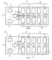
- FIG. 8 shows a schematic plan view of a Fig. 1 Open-end rotor spinning machine 1, on which the method 100 is executed based on the activated fourth drive routine 50.
- the work stations 4 of the open-end rotor spinning machine 1 are combined in accordance with the fourth control routine 50 in three groups A, B and C machine side.
- the arranged on the first side of the machine 16 jobs 4 are summarized in two groups A and B, while arranged on the second side of the machine 18 jobs 4 make up the third group C.
- the workstations 4 are controlled by the central control device 6 in such a way that the workstations 4 of the first group A have the first yarn section A1, the workstations 4 of the second Group B, the second yarn section B1 and the jobs 4 of the third group C produce the third yarn section C1.
- an exemplary embodiment comprises a "and / or" link between a first feature and a second feature
- this can be read so that the embodiment according to one embodiment, both the first feature and the second feature and according to another embodiment, either only the first Feature or only the second feature.
Landscapes
- Engineering & Computer Science (AREA)
- Mechanical Engineering (AREA)
- Textile Engineering (AREA)
- Human Computer Interaction (AREA)
- Manufacturing & Machinery (AREA)
- Physics & Mathematics (AREA)
- General Physics & Mathematics (AREA)
- Automation & Control Theory (AREA)
- Quality & Reliability (AREA)
- Spinning Or Twisting Of Yarns (AREA)
- Looms (AREA)
Applications Claiming Priority (1)
| Application Number | Priority Date | Filing Date | Title |
|---|---|---|---|
| DE102015012214.2A DE102015012214A1 (de) | 2015-09-17 | 2015-09-17 | Verfahren zum Anpassen einer eine Garnpartieherstellung betreffenden werksseitigen Auslegung einer Offenend-Rotorspinnmaschine |
Publications (2)
| Publication Number | Publication Date |
|---|---|
| EP3144418A1 true EP3144418A1 (fr) | 2017-03-22 |
| EP3144418B1 EP3144418B1 (fr) | 2021-11-10 |
Family
ID=56738036
Family Applications (1)
| Application Number | Title | Priority Date | Filing Date |
|---|---|---|---|
| EP16184725.6A Active EP3144418B1 (fr) | 2015-09-17 | 2016-08-18 | Procede d'adaptation d'une conception usine concernant une fabrication de lot de fil d'un metier a tisser a rotor a extremite ouverte |
Country Status (3)
| Country | Link |
|---|---|
| EP (1) | EP3144418B1 (fr) |
| CN (1) | CN106948050B (fr) |
| DE (1) | DE102015012214A1 (fr) |
Cited By (2)
| Publication number | Priority date | Publication date | Assignee | Title |
|---|---|---|---|---|
| EP3604642A1 (fr) * | 2018-08-01 | 2020-02-05 | Maschinenfabrik Rieter AG | Procédé de fonctionnement d'une machine textile et machine textile |
| CN111198524A (zh) * | 2019-12-27 | 2020-05-26 | 苏州数设科技有限公司 | 产品数据的处理方法及装置 |
Families Citing this family (4)
| Publication number | Priority date | Publication date | Assignee | Title |
|---|---|---|---|---|
| CN108792108B (zh) * | 2018-06-26 | 2020-06-05 | 康赛妮集团有限公司 | 一种筒纱全自动包装存储一体智能化集成方法 |
| DE102019116646A1 (de) * | 2019-06-19 | 2020-12-24 | Maschinenfabrik Rieter Ag | Verfahren zum Betreiben einer teil- oder vollautomatischen, kreuzspulenherstellenden Spinnmaschine |
| DE102020106124A1 (de) * | 2020-03-06 | 2021-09-09 | Maschinenfabrik Rieter Ag | Verfahren zum Betreiben einer Spinnmaschine sowie Spinnmaschine |
| DE102020134251A1 (de) | 2020-12-18 | 2022-06-23 | Maschinenfabrik Rieter Ag | Verfahren zum Betreiben einer teil- oder vollautomatischen Spinnmaschine, insbesondere einer Offenend-Rotorspinnmaschine, sowie Spinnmaschine |
Citations (7)
| Publication number | Priority date | Publication date | Assignee | Title |
|---|---|---|---|---|
| DE19836065A1 (de) | 1998-08-10 | 2000-02-17 | Schlafhorst & Co W | Filterkammer für eine Textilmaschine |
| EP1283288A2 (fr) | 2001-08-09 | 2003-02-12 | W. SCHLAFHORST AG & CO. | Procédé et dispositif de rattache pour un métier à filer à bout libre |
| DE10142976A1 (de) * | 2001-09-01 | 2003-03-20 | Rieter Ingolstadt Spinnerei | Textilanlage mit einer Steuereinrichtung zur Bereitstellung partiebezogener Betriebsdaten |
| WO2005035843A2 (fr) * | 2003-10-16 | 2005-04-21 | Saurer Gmbh & Co. Kg | Machine a filer a rotor |
| WO2006090082A1 (fr) * | 2005-02-23 | 2006-08-31 | Ritm | Methode de gestion des reglages d'unites de production que presente une installation de transformation de matieres textiles |
| EP2955143A1 (fr) * | 2014-06-11 | 2015-12-16 | Saurer Germany GmbH & Co. KG | Machine textile semi-automatique fabriquant des bobines |
| DE102014008814A1 (de) | 2014-06-11 | 2015-12-17 | Saurer Germany Gmbh & Co. Kg | Semiautomatische Offenend-Rotorspinnmaschine |
Family Cites Families (8)
| Publication number | Priority date | Publication date | Assignee | Title |
|---|---|---|---|---|
| DE19930714C5 (de) * | 1999-07-02 | 2015-04-09 | Rieter Ingolstadt Gmbh | Textilmaschine mit einer Vielzahl gleichartiger Arbeitsstellen |
| JP4145258B2 (ja) * | 2004-02-24 | 2008-09-03 | 津田駒工業株式会社 | 繊維機械の設定装置 |
| CN201031275Y (zh) * | 2007-01-18 | 2008-03-05 | 欧瑞康纺织有限及两合公司 | 用于生产捻线筒管的纺织机 |
| DE102007056561A1 (de) * | 2007-08-25 | 2009-02-26 | Oerlikon Textile Gmbh & Co. Kg | Kreuzspulen herstellende Textilmaschine |
| JP2009199388A (ja) * | 2008-02-22 | 2009-09-03 | Murata Mach Ltd | 制御プログラム作成プログラム、及び制御プログラムの作成方法、繊維機械システム |
| DE102008056288A1 (de) * | 2008-11-08 | 2010-05-12 | Oerlikon Textile Gmbh & Co. Kg | Verfahren zum Betreiben einer Offenend-Spinnmaschine und Offenend-Spinnmaschine |
| JP5382475B2 (ja) * | 2008-11-14 | 2014-01-08 | ウステル・テヒノロジーズ・アクチエンゲゼルシヤフト | 繊維機械における製造過程を監視する方法 |
| JP5717755B2 (ja) * | 2009-12-11 | 2015-05-13 | エーリコン テクスティル ゲゼルシャフト ミット ベシュレンクテル ハフツング ウント コンパニー コマンディートゲゼルシャフトOerlikon Textile GmbH & Co. KG | 制御装置 |
-
2015
- 2015-09-17 DE DE102015012214.2A patent/DE102015012214A1/de not_active Withdrawn
-
2016
- 2016-08-18 EP EP16184725.6A patent/EP3144418B1/fr active Active
- 2016-09-18 CN CN201610829032.1A patent/CN106948050B/zh active Active
Patent Citations (8)
| Publication number | Priority date | Publication date | Assignee | Title |
|---|---|---|---|---|
| DE19836065A1 (de) | 1998-08-10 | 2000-02-17 | Schlafhorst & Co W | Filterkammer für eine Textilmaschine |
| EP1283288A2 (fr) | 2001-08-09 | 2003-02-12 | W. SCHLAFHORST AG & CO. | Procédé et dispositif de rattache pour un métier à filer à bout libre |
| DE10142976A1 (de) * | 2001-09-01 | 2003-03-20 | Rieter Ingolstadt Spinnerei | Textilanlage mit einer Steuereinrichtung zur Bereitstellung partiebezogener Betriebsdaten |
| WO2005035843A2 (fr) * | 2003-10-16 | 2005-04-21 | Saurer Gmbh & Co. Kg | Machine a filer a rotor |
| WO2006090082A1 (fr) * | 2005-02-23 | 2006-08-31 | Ritm | Methode de gestion des reglages d'unites de production que presente une installation de transformation de matieres textiles |
| EP2955143A1 (fr) * | 2014-06-11 | 2015-12-16 | Saurer Germany GmbH & Co. KG | Machine textile semi-automatique fabriquant des bobines |
| DE102014008814A1 (de) | 2014-06-11 | 2015-12-17 | Saurer Germany Gmbh & Co. Kg | Semiautomatische Offenend-Rotorspinnmaschine |
| EP2966201A2 (fr) * | 2014-06-11 | 2016-01-13 | Saurer Germany GmbH & Co. KG | Métier à tisser à rotor semi-automatique à extrémité ouverte |
Cited By (3)
| Publication number | Priority date | Publication date | Assignee | Title |
|---|---|---|---|---|
| EP3604642A1 (fr) * | 2018-08-01 | 2020-02-05 | Maschinenfabrik Rieter AG | Procédé de fonctionnement d'une machine textile et machine textile |
| US11091854B2 (en) | 2018-08-01 | 2021-08-17 | Maschinenfabrik Rieter Ag | Method for operating a textile machine, and textile machine |
| CN111198524A (zh) * | 2019-12-27 | 2020-05-26 | 苏州数设科技有限公司 | 产品数据的处理方法及装置 |
Also Published As
| Publication number | Publication date |
|---|---|
| DE102015012214A1 (de) | 2017-03-23 |
| CN106948050B (zh) | 2019-03-22 |
| EP3144418B1 (fr) | 2021-11-10 |
| CN106948050A (zh) | 2017-07-14 |
Similar Documents
| Publication | Publication Date | Title |
|---|---|---|
| EP3144418B1 (fr) | Procede d'adaptation d'une conception usine concernant une fabrication de lot de fil d'un metier a tisser a rotor a extremite ouverte | |
| EP2966201B1 (fr) | Machine de filage à bout libre semi-automatique | |
| EP3100971B1 (fr) | Procede de fonctionnement d'une machine textile comprenant des organes de manutention propres a chaque poste de travail pour le re-attachement d'un fil et machine textile comprenant des organes de manutention | |
| EP3168179B1 (fr) | Procede d'operation d'une machine textile produisant des bobines croisees | |
| EP2028298B1 (fr) | Machine textile | |
| EP2955143B1 (fr) | Machine textile semi-automatique fabriquant des bobines | |
| EP3760772B1 (fr) | Optimisation du fonctionnement d'un métier à filer | |
| EP2762617B1 (fr) | Procédé d'optimisation de changement de lot sur un métier à filer à fibres libérées | |
| EP1749906A2 (fr) | Arrangement de rattachement pour une métier à filer à bout libre à rotor | |
| WO2007147483A1 (fr) | Métier à filer | |
| EP1238273B1 (fr) | Procede pour commander une machine a texturer, et machine a texturer | |
| EP3757264A1 (fr) | Procédé de fonctionnement d'un métier à filer à filetage croisé partiellement ou entièrement automatique | |
| EP2292816A2 (fr) | Machine de filature open-end | |
| EP3184680B1 (fr) | Procédé de commande d'un processus de pose destiné à rattacher un fil dans un poste de travail d'une machine textile | |
| EP3617108B1 (fr) | Machine textile et procédé de commande d'une machine textile | |
| CH714412A1 (de) | Verfahren zum Betreiben einer Spulmaschine zum Umspulen von Kopsen einer vorangehenden Ringspinnmaschine. | |
| EP3719186B1 (fr) | Procédé de fonctionnement d'une machine textile ainsi que machine textile | |
| DE102007043417A1 (de) | Offenend-Spinnmaschine | |
| DE102015118987A1 (de) | Verfahren zum Betreiben einer Spinnmaschine mit einer vollautomatischen Anspinnvorrichtung sowie Spinnmaschine mit einer vollautomatischen Anspinnvorrichtung | |
| DE102012007987A1 (de) | Verfahren und Vorrichtung zum kontinuierlichen Abziehen und Aufspulen mehrerer Fäden | |
| EP1675978B1 (fr) | Machine a filer a rotor | |
| EP3710619A1 (fr) | Dispositif de filage à l'état fondu | |
| EP2534285B1 (fr) | Dispositif destiné à tirer et enrouler une pluralité de fils synthétiques | |
| DE102007038871A1 (de) | Verfahren zum Anspinnen an Textilmaschinen mit einer Mehrzahl von Spinnstellen | |
| EP1920090A1 (fr) | Dispositif de filature par fusion et d'enroulement d'une pluralite de fils ; mode de fonctionnement d'un tel dispositif |
Legal Events
| Date | Code | Title | Description |
|---|---|---|---|
| PUAI | Public reference made under article 153(3) epc to a published international application that has entered the european phase |
Free format text: ORIGINAL CODE: 0009012 |
|
| STAA | Information on the status of an ep patent application or granted ep patent |
Free format text: STATUS: THE APPLICATION HAS BEEN PUBLISHED |
|
| AK | Designated contracting states |
Kind code of ref document: A1 Designated state(s): AL AT BE BG CH CY CZ DE DK EE ES FI FR GB GR HR HU IE IS IT LI LT LU LV MC MK MT NL NO PL PT RO RS SE SI SK SM TR |
|
| AX | Request for extension of the european patent |
Extension state: BA ME |
|
| STAA | Information on the status of an ep patent application or granted ep patent |
Free format text: STATUS: REQUEST FOR EXAMINATION WAS MADE |
|
| 17P | Request for examination filed |
Effective date: 20170922 |
|
| RBV | Designated contracting states (corrected) |
Designated state(s): AL AT BE BG CH CY CZ DE DK EE ES FI FR GB GR HR HU IE IS IT LI LT LU LV MC MK MT NL NO PL PT RO RS SE SI SK SM TR |
|
| RAP1 | Party data changed (applicant data changed or rights of an application transferred) |
Owner name: SAURER SPINNING SOLUTIONS GMBH & CO. KG |
|
| STAA | Information on the status of an ep patent application or granted ep patent |
Free format text: STATUS: EXAMINATION IS IN PROGRESS |
|
| 17Q | First examination report despatched |
Effective date: 20190814 |
|
| GRAP | Despatch of communication of intention to grant a patent |
Free format text: ORIGINAL CODE: EPIDOSNIGR1 |
|
| STAA | Information on the status of an ep patent application or granted ep patent |
Free format text: STATUS: GRANT OF PATENT IS INTENDED |
|
| INTG | Intention to grant announced |
Effective date: 20210614 |
|
| GRAS | Grant fee paid |
Free format text: ORIGINAL CODE: EPIDOSNIGR3 |
|
| GRAA | (expected) grant |
Free format text: ORIGINAL CODE: 0009210 |
|
| STAA | Information on the status of an ep patent application or granted ep patent |
Free format text: STATUS: THE PATENT HAS BEEN GRANTED |
|
| AK | Designated contracting states |
Kind code of ref document: B1 Designated state(s): AL AT BE BG CH CY CZ DE DK EE ES FI FR GB GR HR HU IE IS IT LI LT LU LV MC MK MT NL NO PL PT RO RS SE SI SK SM TR |
|
| REG | Reference to a national code |
Ref country code: GB Ref legal event code: FG4D Free format text: NOT ENGLISH |
|
| REG | Reference to a national code |
Ref country code: AT Ref legal event code: REF Ref document number: 1446176 Country of ref document: AT Kind code of ref document: T Effective date: 20211115 Ref country code: CH Ref legal event code: EP |
|
| REG | Reference to a national code |
Ref country code: DE Ref legal event code: R096 Ref document number: 502016014108 Country of ref document: DE |
|
| REG | Reference to a national code |
Ref country code: IE Ref legal event code: FG4D Free format text: LANGUAGE OF EP DOCUMENT: GERMAN |
|
| REG | Reference to a national code |
Ref country code: LT Ref legal event code: MG9D |
|
| REG | Reference to a national code |
Ref country code: NL Ref legal event code: MP Effective date: 20211110 |
|
| PG25 | Lapsed in a contracting state [announced via postgrant information from national office to epo] |
Ref country code: RS Free format text: LAPSE BECAUSE OF FAILURE TO SUBMIT A TRANSLATION OF THE DESCRIPTION OR TO PAY THE FEE WITHIN THE PRESCRIBED TIME-LIMIT Effective date: 20211110 Ref country code: LT Free format text: LAPSE BECAUSE OF FAILURE TO SUBMIT A TRANSLATION OF THE DESCRIPTION OR TO PAY THE FEE WITHIN THE PRESCRIBED TIME-LIMIT Effective date: 20211110 Ref country code: FI Free format text: LAPSE BECAUSE OF FAILURE TO SUBMIT A TRANSLATION OF THE DESCRIPTION OR TO PAY THE FEE WITHIN THE PRESCRIBED TIME-LIMIT Effective date: 20211110 Ref country code: BG Free format text: LAPSE BECAUSE OF FAILURE TO SUBMIT A TRANSLATION OF THE DESCRIPTION OR TO PAY THE FEE WITHIN THE PRESCRIBED TIME-LIMIT Effective date: 20220210 |
|
| PG25 | Lapsed in a contracting state [announced via postgrant information from national office to epo] |
Ref country code: IS Free format text: LAPSE BECAUSE OF FAILURE TO SUBMIT A TRANSLATION OF THE DESCRIPTION OR TO PAY THE FEE WITHIN THE PRESCRIBED TIME-LIMIT Effective date: 20220310 Ref country code: SE Free format text: LAPSE BECAUSE OF FAILURE TO SUBMIT A TRANSLATION OF THE DESCRIPTION OR TO PAY THE FEE WITHIN THE PRESCRIBED TIME-LIMIT Effective date: 20211110 Ref country code: PT Free format text: LAPSE BECAUSE OF FAILURE TO SUBMIT A TRANSLATION OF THE DESCRIPTION OR TO PAY THE FEE WITHIN THE PRESCRIBED TIME-LIMIT Effective date: 20220310 Ref country code: PL Free format text: LAPSE BECAUSE OF FAILURE TO SUBMIT A TRANSLATION OF THE DESCRIPTION OR TO PAY THE FEE WITHIN THE PRESCRIBED TIME-LIMIT Effective date: 20211110 Ref country code: NO Free format text: LAPSE BECAUSE OF FAILURE TO SUBMIT A TRANSLATION OF THE DESCRIPTION OR TO PAY THE FEE WITHIN THE PRESCRIBED TIME-LIMIT Effective date: 20220210 Ref country code: NL Free format text: LAPSE BECAUSE OF FAILURE TO SUBMIT A TRANSLATION OF THE DESCRIPTION OR TO PAY THE FEE WITHIN THE PRESCRIBED TIME-LIMIT Effective date: 20211110 Ref country code: LV Free format text: LAPSE BECAUSE OF FAILURE TO SUBMIT A TRANSLATION OF THE DESCRIPTION OR TO PAY THE FEE WITHIN THE PRESCRIBED TIME-LIMIT Effective date: 20211110 Ref country code: HR Free format text: LAPSE BECAUSE OF FAILURE TO SUBMIT A TRANSLATION OF THE DESCRIPTION OR TO PAY THE FEE WITHIN THE PRESCRIBED TIME-LIMIT Effective date: 20211110 Ref country code: GR Free format text: LAPSE BECAUSE OF FAILURE TO SUBMIT A TRANSLATION OF THE DESCRIPTION OR TO PAY THE FEE WITHIN THE PRESCRIBED TIME-LIMIT Effective date: 20220211 Ref country code: ES Free format text: LAPSE BECAUSE OF FAILURE TO SUBMIT A TRANSLATION OF THE DESCRIPTION OR TO PAY THE FEE WITHIN THE PRESCRIBED TIME-LIMIT Effective date: 20211110 |
|
| PG25 | Lapsed in a contracting state [announced via postgrant information from national office to epo] |
Ref country code: SM Free format text: LAPSE BECAUSE OF FAILURE TO SUBMIT A TRANSLATION OF THE DESCRIPTION OR TO PAY THE FEE WITHIN THE PRESCRIBED TIME-LIMIT Effective date: 20211110 Ref country code: SK Free format text: LAPSE BECAUSE OF FAILURE TO SUBMIT A TRANSLATION OF THE DESCRIPTION OR TO PAY THE FEE WITHIN THE PRESCRIBED TIME-LIMIT Effective date: 20211110 Ref country code: RO Free format text: LAPSE BECAUSE OF FAILURE TO SUBMIT A TRANSLATION OF THE DESCRIPTION OR TO PAY THE FEE WITHIN THE PRESCRIBED TIME-LIMIT Effective date: 20211110 Ref country code: EE Free format text: LAPSE BECAUSE OF FAILURE TO SUBMIT A TRANSLATION OF THE DESCRIPTION OR TO PAY THE FEE WITHIN THE PRESCRIBED TIME-LIMIT Effective date: 20211110 Ref country code: DK Free format text: LAPSE BECAUSE OF FAILURE TO SUBMIT A TRANSLATION OF THE DESCRIPTION OR TO PAY THE FEE WITHIN THE PRESCRIBED TIME-LIMIT Effective date: 20211110 |
|
| REG | Reference to a national code |
Ref country code: DE Ref legal event code: R097 Ref document number: 502016014108 Country of ref document: DE |
|
| PLBE | No opposition filed within time limit |
Free format text: ORIGINAL CODE: 0009261 |
|
| STAA | Information on the status of an ep patent application or granted ep patent |
Free format text: STATUS: NO OPPOSITION FILED WITHIN TIME LIMIT |
|
| 26N | No opposition filed |
Effective date: 20220811 |
|
| PG25 | Lapsed in a contracting state [announced via postgrant information from national office to epo] |
Ref country code: AL Free format text: LAPSE BECAUSE OF FAILURE TO SUBMIT A TRANSLATION OF THE DESCRIPTION OR TO PAY THE FEE WITHIN THE PRESCRIBED TIME-LIMIT Effective date: 20211110 |
|
| PG25 | Lapsed in a contracting state [announced via postgrant information from national office to epo] |
Ref country code: SI Free format text: LAPSE BECAUSE OF FAILURE TO SUBMIT A TRANSLATION OF THE DESCRIPTION OR TO PAY THE FEE WITHIN THE PRESCRIBED TIME-LIMIT Effective date: 20211110 |
|
| PG25 | Lapsed in a contracting state [announced via postgrant information from national office to epo] |
Ref country code: MC Free format text: LAPSE BECAUSE OF FAILURE TO SUBMIT A TRANSLATION OF THE DESCRIPTION OR TO PAY THE FEE WITHIN THE PRESCRIBED TIME-LIMIT Effective date: 20211110 |
|
| GBPC | Gb: european patent ceased through non-payment of renewal fee |
Effective date: 20220818 |
|
| PG25 | Lapsed in a contracting state [announced via postgrant information from national office to epo] |
Ref country code: LU Free format text: LAPSE BECAUSE OF NON-PAYMENT OF DUE FEES Effective date: 20220818 |
|
| REG | Reference to a national code |
Ref country code: BE Ref legal event code: MM Effective date: 20220831 |
|
| PG25 | Lapsed in a contracting state [announced via postgrant information from national office to epo] |
Ref country code: IE Free format text: LAPSE BECAUSE OF NON-PAYMENT OF DUE FEES Effective date: 20220818 Ref country code: FR Free format text: LAPSE BECAUSE OF NON-PAYMENT OF DUE FEES Effective date: 20220831 |
|
| PG25 | Lapsed in a contracting state [announced via postgrant information from national office to epo] |
Ref country code: BE Free format text: LAPSE BECAUSE OF NON-PAYMENT OF DUE FEES Effective date: 20220831 |
|
| REG | Reference to a national code |
Ref country code: AT Ref legal event code: MM01 Ref document number: 1446176 Country of ref document: AT Kind code of ref document: T Effective date: 20220818 |
|
| PG25 | Lapsed in a contracting state [announced via postgrant information from national office to epo] |
Ref country code: GB Free format text: LAPSE BECAUSE OF NON-PAYMENT OF DUE FEES Effective date: 20220818 Ref country code: AT Free format text: LAPSE BECAUSE OF NON-PAYMENT OF DUE FEES Effective date: 20220818 |
|
| PG25 | Lapsed in a contracting state [announced via postgrant information from national office to epo] |
Ref country code: HU Free format text: LAPSE BECAUSE OF FAILURE TO SUBMIT A TRANSLATION OF THE DESCRIPTION OR TO PAY THE FEE WITHIN THE PRESCRIBED TIME-LIMIT; INVALID AB INITIO Effective date: 20160818 |
|
| PG25 | Lapsed in a contracting state [announced via postgrant information from national office to epo] |
Ref country code: CY Free format text: LAPSE BECAUSE OF FAILURE TO SUBMIT A TRANSLATION OF THE DESCRIPTION OR TO PAY THE FEE WITHIN THE PRESCRIBED TIME-LIMIT Effective date: 20211110 |
|
| PG25 | Lapsed in a contracting state [announced via postgrant information from national office to epo] |
Ref country code: MK Free format text: LAPSE BECAUSE OF FAILURE TO SUBMIT A TRANSLATION OF THE DESCRIPTION OR TO PAY THE FEE WITHIN THE PRESCRIBED TIME-LIMIT Effective date: 20211110 |
|
| PG25 | Lapsed in a contracting state [announced via postgrant information from national office to epo] |
Ref country code: TR Free format text: LAPSE BECAUSE OF FAILURE TO SUBMIT A TRANSLATION OF THE DESCRIPTION OR TO PAY THE FEE WITHIN THE PRESCRIBED TIME-LIMIT Effective date: 20211110 |
|
| PG25 | Lapsed in a contracting state [announced via postgrant information from national office to epo] |
Ref country code: MT Free format text: LAPSE BECAUSE OF FAILURE TO SUBMIT A TRANSLATION OF THE DESCRIPTION OR TO PAY THE FEE WITHIN THE PRESCRIBED TIME-LIMIT Effective date: 20211110 |
|
| PGFP | Annual fee paid to national office [announced via postgrant information from national office to epo] |
Ref country code: IT Payment date: 20240830 Year of fee payment: 9 |
|
| PGFP | Annual fee paid to national office [announced via postgrant information from national office to epo] |
Ref country code: DE Payment date: 20250819 Year of fee payment: 10 |
|
| PGFP | Annual fee paid to national office [announced via postgrant information from national office to epo] |
Ref country code: CH Payment date: 20250901 Year of fee payment: 10 |
|
| PGFP | Annual fee paid to national office [announced via postgrant information from national office to epo] |
Ref country code: CZ Payment date: 20250805 Year of fee payment: 10 |
|
| PG25 | Lapsed in a contracting state [announced via postgrant information from national office to epo] |
Ref country code: IT Free format text: LAPSE BECAUSE OF NON-PAYMENT OF DUE FEES Effective date: 20250818 |