EP1997973A2 - Ensemble de support pour panneaux reliés - Google Patents
Ensemble de support pour panneaux reliés Download PDFInfo
- Publication number
- EP1997973A2 EP1997973A2 EP08153616A EP08153616A EP1997973A2 EP 1997973 A2 EP1997973 A2 EP 1997973A2 EP 08153616 A EP08153616 A EP 08153616A EP 08153616 A EP08153616 A EP 08153616A EP 1997973 A2 EP1997973 A2 EP 1997973A2
- Authority
- EP
- European Patent Office
- Prior art keywords
- shaped
- joining element
- joining
- support group
- shaped portion
- Prior art date
- Legal status (The legal status is an assumption and is not a legal conclusion. Google has not performed a legal analysis and makes no representation as to the accuracy of the status listed.)
- Withdrawn
Links
Images






Classifications
-
- E—FIXED CONSTRUCTIONS
- E04—BUILDING
- E04C—STRUCTURAL ELEMENTS; BUILDING MATERIALS
- E04C3/00—Structural elongated elements designed for load-supporting
- E04C3/02—Joists; Girders, trusses, or trusslike structures, e.g. prefabricated; Lintels; Transoms; Braces
- E04C3/04—Joists; Girders, trusses, or trusslike structures, e.g. prefabricated; Lintels; Transoms; Braces of metal
- E04C3/06—Joists; Girders, trusses, or trusslike structures, e.g. prefabricated; Lintels; Transoms; Braces of metal with substantially solid, i.e. unapertured, web
- E04C3/07—Joists; Girders, trusses, or trusslike structures, e.g. prefabricated; Lintels; Transoms; Braces of metal with substantially solid, i.e. unapertured, web at least partly of bent or otherwise deformed strip- or sheet-like material
-
- E—FIXED CONSTRUCTIONS
- E04—BUILDING
- E04D—ROOF COVERINGS; SKY-LIGHTS; GUTTERS; ROOF-WORKING TOOLS
- E04D3/00—Roof covering by making use of flat or curved slabs or stiff sheets
- E04D3/24—Roof covering by making use of flat or curved slabs or stiff sheets with special cross-section, e.g. with corrugations on both sides, with ribs, flanges, or the like
- E04D3/28—Roof covering by making use of flat or curved slabs or stiff sheets with special cross-section, e.g. with corrugations on both sides, with ribs, flanges, or the like of glass or other translucent material
-
- E—FIXED CONSTRUCTIONS
- E04—BUILDING
- E04D—ROOF COVERINGS; SKY-LIGHTS; GUTTERS; ROOF-WORKING TOOLS
- E04D3/00—Roof covering by making use of flat or curved slabs or stiff sheets
- E04D3/24—Roof covering by making use of flat or curved slabs or stiff sheets with special cross-section, e.g. with corrugations on both sides, with ribs, flanges, or the like
- E04D3/32—Roof covering by making use of flat or curved slabs or stiff sheets with special cross-section, e.g. with corrugations on both sides, with ribs, flanges, or the like of plastics, fibrous materials, or asbestos cement
-
- E—FIXED CONSTRUCTIONS
- E04—BUILDING
- E04D—ROOF COVERINGS; SKY-LIGHTS; GUTTERS; ROOF-WORKING TOOLS
- E04D3/00—Roof covering by making use of flat or curved slabs or stiff sheets
- E04D3/24—Roof covering by making use of flat or curved slabs or stiff sheets with special cross-section, e.g. with corrugations on both sides, with ribs, flanges, or the like
- E04D3/28—Roof covering by making use of flat or curved slabs or stiff sheets with special cross-section, e.g. with corrugations on both sides, with ribs, flanges, or the like of glass or other translucent material
- E04D2003/285—Roof covering by making use of flat or curved slabs or stiff sheets with special cross-section, e.g. with corrugations on both sides, with ribs, flanges, or the like of glass or other translucent material with specially profiled marginal portions for connecting purposes
Definitions
- the present invention refers to a support group for panel joining elements and panel assembly, panel joining elements and support groups for the panel joining elements.
- such assembly and such group can be used in the building industry, for example in the roofing structures, curtain walls, protection walls and the like.
- panels is meant to indicate both the actual panels and the slabs or walls just like any other similar elements which cooperate, in the example, in the construction of such structures.
- Both the panels and the slabs as well as the joining elements can be made of different material, such as for example polycarbonate, aluminium or other specific resins.
- Some of these panel joining elements assemblies known do not provide a direct and easy associability between the components; as a matter of fact, it is possible that a first panel be easily inserted into the joining element, while a second panel is harder to insert in the presence of the first inserted panel.
- Another possible drawback is the one related to the fact that, once the panels and the joining element have been connected, there lacks a good sealing between the parts, hence leading to the possibility of disengaging on one side and leakage through the assembly on the other.
- a further drawback also lies in the possible detachment of the panel system, even leading to leakage of water, due to the frequent occurrence of atmospheric events of a considerable intensity which occur more frequently nowadays.
- the objective of the present invention is that of providing a device capable of overcoming the abovementioned drawbacks of the known art in an extremely simple, inexpensive and particularly functional manner.
- Another objective of the present invention is that of providing a support group for panel joining elements and panel assembly, panel joining elements, and support groups for the panel joining elements provided with good resistance characteristics both general and at the joint zone.
- Another objective of the present invention is that of providing a support group for panel joining elements and a panel assembly, panel joining elements, and support groups for the panel joining elements provided with mechanical resistance flexible depending on the requirement.
- another objective of the present invention is that of providing a support group for the panel joining elements and a panel assembly, panel joining elements, and support groups for the panel joining elements capable of ensuring stable positioning between the parts, alongside a good sealing against water, air and leakages.
- the assembly and the group of the invention must be capable insulating against possible leakages due to accidental and inadvertent causes.
- Another objective is that of providing a support group for panel joining elements and panel assembly, panel joining elements, and support groups for the panel joining elements capable of solving the problem concerning breakages due to thermal expansion between the framework and the assembly itself.
- a support group for panel joining elements and panel assembly is shown a support group for panel joining elements and panel assembly, panel joining elements, and support groups for the panel joining elements.
- Such assembly comprises at least two panels 11 and 12, at least one joining element 13, 113, adapted to receive on the upper part and to hold an end of each of the two adjacent panels 11 and 12 engaging them in a stable manner and having on the lower part at least one shaped portion 49, and at least one support group 100, 200, 300, 400.
- At least one shaped portion 49 of the joining element 13, 113 is a dovetail-shaped portion but, alternatively, it can be of any geometrical shape such to provide a stable coupling, preferably sliding, having a shape complementary to it.
- the support group 100, 200, 300, 400 according to the present invention is provided on the upper part with at least a first portion 149', 249', 349', 449', shaped in a manner complementary to the at least one shaped portion 49 of the joining element 13, 113 and with constraint means 149", 203, 204, 349", 449" for connecting one of its lower portions 103, 203, 303, 403 with another element, such as for example another support group or a framework.
- the at least one first portion 149', 249', 349', 449' shall be at least one longitudinal counter-guide in such a manner to connect the two elements in a sliding manner longitudinally and prevent them from decoupling in a transverse and orthogonal manner at the same time.
- FIG. 11-13 is shown a first exemplification of an assembly of two panels 11 and 12 and of a joining element 13, in particular for the building industry, associated to which according to the present invention can be a support group 100, 200, 300, 400 as described above.
- the panels 11 and 12 are made of polycarbonate and they have a honeycomb structure provided by a plurality of ribs 14 of any type arranged between two main external surfaces 10, 28, 29.
- honeycomb structure has a rectangular geometry thus providing better thermal insulation and higher resistance to loads, as well as high flexibility.
- the joining element 13 is preferably made of polycarbonate, synthetic resin or other similar material.
- the section illustrated shows the type of coupling which furthermore extends along the entire length of the two panels 11 and 12 to be connected, as well as the joining element 13 which features the same extension and serves as a support element.
- each panel 11 and 12 At the two opposite ends of each panel 11 and 12 provided are widened head extensions 15 and 16 with the body tapered towards the widened end (only one of which is shown for each panel).
- the two extensions 15 and 16 are arranged almost forming a square with respect to a base of the panel 11 or 12.
- these extensions 15 and 16 respectively have an external side surface 17 of the panel 11 which is arranged opposite to the surface 18 of the other panel 12 both of which slant slightly inwards the panel itself.
- This aims at facilitating their coupling with the opposite faces of a pressure element 19 which is extended centrally inside the joining element 13, U-shaped, when the latter is arranged constraining the two extensions 15 and 16 of different panels 11 and 12 in a coupling manner.
- the extensions 15 and 16 in the portion of their body facing inwards each panel 11 and 12, have a pair of zones having a slanting surface 20 and 21 in the same direction of the tapering.
- the first zone having a slanting surface 20 is arranged beneath the widened head, while the second zone having a slanting surface 21 is provided directly on the side of the widened head itself.
- These two zones with slanting surfaces 20 and 21 are blended to provide a housing 22, as well as a protrusion 23.
- the two zones having a slanting surface 20 and 21 facilitate the insertion of the single extension 15 and 16 into the joining element 13 cooperating with a zone having a slanting surface 24 provided on each of the two extensions 15 and 16 and converging inwards and towards the central base 25 of the joining element 13 of the assembly.
- Abutting in the housing 22 is a protrusion or a widened part 26, radially projecting inwards the joining element 13, provided with rounded end.
- Such rounded end is also provided by a pair of converging zones having a slanting surface 24 and 27 which extend from the two U-shaped wings inwards.
- the zone having a slanting surface 24 is the one that facilitates the insertion of the extension 15 and 16 into the joining element 13 sliding on the zone having a slanting surface 21 of the same extensions.
- the joining element 13 has a U-shaped section, it is also made having a honeycomb structure and it provides for a pressure element 19 which extends centrally within it.
- This pressure element 19 is cone-shaped towards the tip hence facilitating its insertion between the two extensions 15 and 16 of two adjacent panels 11 and 12 to be connected. Such cone-shape guides the coupling and the positioning of the two panels due to the cooperation of the external side surfaces 17 and 18 of the panels 11 and 12.
- the pressure element 19 cooperates to arrange and to engage a first inserted panel 11, facilitating precisely the insertion operation of the second panel 12.
- This pressure coupling does not allow the water, in case of roofing or other similar applications, to go into the assembly thus formed, hence keeping the assembly totally watertight against the water flowing on its surface.
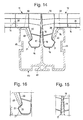
- Figures 14-16 show a further second exemplification of an assembly of two panels 11 and 12 having a joining element 113, associated to which, according to the present invention, there can be a support group 100, 200, 300, 400 as described above, in which identical reference numbers are used for the identical parts, or a "1" is possibly added for the parts functionally similar.
- the two panels 11 and 12 are identical to the preceding ones, while the joining element 113 is made of aluminium, alloys of the same or other similar material, for example produced through extrusion.
- inward curved extensions 40 Provided at the free ends of the two side wings of the joining element 113 are inward curved extensions 40 whose ends 41 which abut in the housing 22 provided for on the extensions 15 and 16 of the panels 11 and 12. Even such curved extensions 40 provide for a rounded end 41 adapted to facilitate the sliding between the parts. Furthermore, this curved extension 40 provides for its inclination in such a manner to be similar to the slanted surface 24 and cooperate sliding on the zone having a slanting surface 21 of the extensions 15 and 16.
- the pressure element 19 cone-shaped and tapered towards the tip, hence facilitating its insertion between the two extensions 15 and 16 of two panels 11 and 12 and provides the coupling between the external side surfaces 17 and 18 of the panels 11 and 12.
- recesses or housing seat 45 can be provided on the side external walls of the joining element 13 or 113.
- the joining element 13 and 113 provide for a shaped portion 49.
- At the lower part of the joining element 13 and 113 is at least one support element 100, 200, 300 and 400.
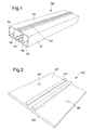
- such support group 100, 200, 300, 400 is a parallelepiped element with a rectangular section 100, preferably hollow, provided with four main external surfaces 101, 102, 103, 104.
- provided on the upper surface 101 is at least a first portion 149' shaped in a manner complementary to the mentioned at least one shaped portion 49 of the joining element 13, 113, while provided on the lower surface 102 is a second portion 149" substantially shaped in a manner identical to the shaped portion 49 of the joining element 13, 113.
- This second shaped element 149" serves as a constraint for connecting the lower surface 102 of the parallelepiped element 100 to another element which could be the framework or any other element.
- the parallelepiped element 100 in case the parallelepiped element 100 is hollow, it further comprises two complete surfaces 105, 106, with the function of increasing the rigidity of the assembly, parallel to the two side surfaces 102, 104 dividing the internal volume of the element 100 into three separate parts.
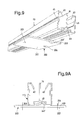
- this parallelepiped element 100 is connected on its upper part in a sliding manner longitudinally to their development to the related joining element 13, 113 and at its lower part, as observable in figures 6 and 6A it can be associated to another parallelepiped element 100; this allows obtaining high mechanical resistance of the assembly.
- the parallelepiped element 100 can comprise on the upper surface 101 holes 703, 704, 801, 802 preferably arranged at opposite sides with respect to the first shaped portion 149' to facilitate fastening the element using tools.
- the panel elements 11 and 12 are not shown. However, these panel elements are to be provided for connected on the upper part to the at least one joining element 13, 113 as shown in figures 11-16 .
- FIG. 1 In the figure is shown another example of a support group 100, 200, 300, 400 according to the invention.
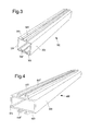
- Such support group 100, 200, 300, 400 comprises at least one laminar element 200, having a thin section to allow minimising the space between the framework and the panels.
- Such laminar element 200 has two parallel main external surfaces 201, 202, in which provided on the upper surface 201 is at least a first portion 249' shaped in a manner complementary to the at least one shaped portion 49 of the joining element 13, 113.
- the constraint means 149", 203, 204, 349", 449" provided for connecting the lower portion 202 of the laminar element 200 with another element are at least two through holes 203, 204 arranged at opposite sides with respect to the first shaped portion 249' which can advantageously serve as seats for screw or plug elements for connecting the element 200 with another element.
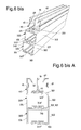
- Figure 3 shows another example of a support group 100, 200, 300, 400 according to the invention comprising a parallelepiped element having a substantially square section 300 having, preferably, the same width of the related joining element 13, 113.
- Such element 300 preferably hollow, is provided with four main external surfaces 301, 302, 303, 304, in which provided on the upper surface 301 is at least one first portion 349' shaped in a manner complementary to the at least one shaped portion 49 of the joining element 13, 113, and in which provided on the lower surface 302 is a second portion 349" substantially shaped in a manner identical to the shaped portion 49 of the joining element 13, 113.
- Such shaped second portion 349" serves as a constraint means for connecting the lower portion of the at least one substantially square element 300 with another element.
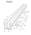
- the support group 100, 200, 300, 400 is a substantially rectangular element 400, preferably hollow, provided with four main external surfaces 401, 402, 403, 404 in which the upper surface 401 is provided with at least one first portion 449' shaped in a manner complementary to the at least one shaped portion 49 of the joining element 13, 113, and the lower surface 402 is provided with at least one second portion 449" shaped in a manner identical to the at least one first portion 449'.
- substantially rectangular element 400 it is possible to construct, according to the present invention, symmetrical assemblies provided in which there can be a support group 400 and two joining elements 13, 113, as observable in figures 10 and 10A , or embodiments with several support groups as described above externally connected to which there will be the related joining elements 13, 113.
- the assembly comprising the panels, the joining element and the support group according to the present invention allows providing particularly efficient structures with respect to the known ones allowing to meet in an entirely easy manner, due to the modularity of the elements of the invention which slide longitudinally between each other, the various load conditions encountered nowadays in the building industry.
- the joining element is no longer in direct contact with the framework but in contact with a special support group which in turn shall either be constrained against the abovementioned framework or against other elements such as other support groups or other joining elements.
- the assembly considerably and advantageously enhances its flexional rigidity allowing, depending on the requirements, fastening against the structure of the continuous or pointwise type.
- the assembly according to the invention reduces the possibilities of breakage due to thermal expansion between the framework and the assembly itself as well as considerably enhancing thermal insulation between the framework and the panels.
- the assembly according to the invention allows constructing a double wall system providing a symmetric architectonic structure and the creation of a larger thermal insulation chamber.
- a support group for panel joining elements, a panel assembly, panel joining elements and support groups for the panel joining elements according to the present invention attains the objectives outlined previously.
Landscapes
- Engineering & Computer Science (AREA)
- Architecture (AREA)
- Civil Engineering (AREA)
- Structural Engineering (AREA)
- Connection Of Plates (AREA)
- Joining Of Building Structures In Genera (AREA)
- Container, Conveyance, Adherence, Positioning, Of Wafer (AREA)
- Finishing Walls (AREA)
Applications Claiming Priority (1)
| Application Number | Priority Date | Filing Date | Title |
|---|---|---|---|
| IT001081A ITMI20071081A1 (it) | 2007-05-28 | 2007-05-28 | Gruppo di supporto per elementi di giunzione di pannelli e assieme di pannelli, elementi di giunzione dei pannelli, e gruppi di supporto per gli elementi di giunzione dei pannelli |
Publications (2)
| Publication Number | Publication Date |
|---|---|
| EP1997973A2 true EP1997973A2 (fr) | 2008-12-03 |
| EP1997973A3 EP1997973A3 (fr) | 2012-09-26 |
Family
ID=39591678
Family Applications (1)
| Application Number | Title | Priority Date | Filing Date |
|---|---|---|---|
| EP08153616A Withdrawn EP1997973A3 (fr) | 2007-05-28 | 2008-03-28 | Ensemble de support pour panneaux reliés |
Country Status (4)
| Country | Link |
|---|---|
| US (1) | US20080295436A1 (fr) |
| EP (1) | EP1997973A3 (fr) |
| CN (1) | CN101338584A (fr) |
| IT (1) | ITMI20071081A1 (fr) |
Families Citing this family (5)
| Publication number | Priority date | Publication date | Assignee | Title |
|---|---|---|---|---|
| US20080016816A1 (en) * | 2006-07-19 | 2008-01-24 | Do Yeon Kim | Beam/Column With Stiffening Stick |
| US7913467B2 (en) * | 2006-07-25 | 2011-03-29 | Zephyros, Inc. | Structural reinforcements |
| CN102317665B (zh) * | 2009-02-18 | 2014-07-02 | 沃尔什知识产权有限公司 | 管道构件 |
| CN104652700A (zh) * | 2014-12-30 | 2015-05-27 | 潘茜茜 | 板材 |
| GB2613371B (en) * | 2021-12-01 | 2024-04-17 | Mar Key Marquees Ltd | Roofing Structure |
Family Cites Families (10)
| Publication number | Priority date | Publication date | Assignee | Title |
|---|---|---|---|---|
| BE460033A (fr) * | ||||
| US2982380A (en) * | 1958-09-22 | 1961-05-02 | Rose Morton Jessup | Connecting means for building structures |
| US3407547A (en) * | 1966-07-20 | 1968-10-29 | Angeles Metal Trim Co | Metallic wall stud structure for supporting shelf brackets |
| GB1234711A (en) * | 1969-03-31 | 1971-06-09 | Metalport S A | Extruded members and assemblies thereof for glazing without putty |
| US4874322A (en) * | 1987-09-28 | 1989-10-17 | Amp Incorporated | Surface applied wiring apparatus |
| CA2089022A1 (fr) * | 1993-02-08 | 1994-08-09 | Vittorio De Zen | Support de toit pouvant resister a des charges elevees, pour maisons modulaires |
| FR2709780B1 (fr) * | 1993-09-06 | 1997-07-11 | Guy Biguet | Gamme d'armatures pour parois translucides et leur dispositif de fabrication. |
| US5644878A (en) * | 1995-01-11 | 1997-07-08 | Sony Corporation | Reusable finish trim for prefabricated clean room wall system |
| FR2804982A1 (fr) * | 2000-02-10 | 2001-08-17 | Jacques Sarrat | Profil porteur "compose", cintre, pour structures legeres, resultant de l'assemblage de trois profils "elementaires" solidarises entre eux |
| IT1317120B1 (it) * | 2000-03-07 | 2003-05-27 | Politec Polimeri Tecnici Sa | Assieme di pannelli e di elementi di giunzione |
-
2007
- 2007-05-28 IT IT001081A patent/ITMI20071081A1/it unknown
-
2008
- 2008-03-28 EP EP08153616A patent/EP1997973A3/fr not_active Withdrawn
- 2008-05-15 US US12/152,604 patent/US20080295436A1/en not_active Abandoned
- 2008-05-27 CN CNA2008101085694A patent/CN101338584A/zh active Pending
Also Published As
| Publication number | Publication date |
|---|---|
| CN101338584A (zh) | 2009-01-07 |
| US20080295436A1 (en) | 2008-12-04 |
| ITMI20071081A1 (it) | 2008-11-29 |
| EP1997973A3 (fr) | 2012-09-26 |
Similar Documents
| Publication | Publication Date | Title |
|---|---|---|
| EP1997973A2 (fr) | Ensemble de support pour panneaux reliés | |
| EP2165027B1 (fr) | Construction avec panneaux modulaires pour le bâtiment | |
| US7775010B2 (en) | Slab bolster coupling | |
| EP1132542B1 (fr) | Ensemble de panneaux et éléments de connexion | |
| EP2165026B1 (fr) | Structure comprenant deux panneaux juxtaposés et un ensemble permettant de fixer les deux panneaux juxtaposés à une structure | |
| ES2873499T3 (es) | Sistema mecánico de trabazón para paneles de construcción | |
| JP5237769B2 (ja) | 異形材レールシステム | |
| HK1221000A1 (zh) | 用於屋顶等的覆盖物 | |
| BRPI0621779B1 (pt) | Construtividade em lingueta para sistemas de travamento de conjunto de painéis de piso | |
| BR0109134A (pt) | Elementos de piso unidos verticalmente compreendendo uma comibinação de elementos de piso diferentes | |
| AU2020201453A1 (en) | Formwork system | |
| CA2894923A1 (fr) | Element de construction compose de deux panneaux avec baguette de raccord | |
| CZ20022662A3 (cs) | Konstrukční prvek pro zřizování stěnových, stropních, podlahových, opěrných, vymezovacích a dělicích stěnových konstrukcí nebo podobně | |
| US10526794B2 (en) | Joint for floors in strips | |
| HK1122084A (en) | Support assembly for interconnected panels | |
| EP3106745A1 (fr) | Systèmes de connexion de luminaire | |
| KR20080088160A (ko) | 데크 결합용 부재 및 데크자재의 결합구조 | |
| CN102648355B (zh) | 用于将两个板件夹持在一起的易碎连接件 | |
| ES2763180T3 (es) | Taco para realizar una unión deslizante entre dos placas | |
| KR101878138B1 (ko) | 단열재 고정구 | |
| JP5716486B2 (ja) | 桁橋の主桁、桁橋の主桁とコンクリート床版の接合部構造、コンクリート床版、桁橋および橋梁 | |
| JP7174474B2 (ja) | シールドセグメント用継手部材 | |
| EP3779213B1 (fr) | Agencement de connexion | |
| US3965958A (en) | Joint assembly and fastener therefor | |
| EP1598582B1 (fr) | Entretoise modulaire pour tuyaux concentriques |
Legal Events
| Date | Code | Title | Description |
|---|---|---|---|
| PUAI | Public reference made under article 153(3) epc to a published international application that has entered the european phase |
Free format text: ORIGINAL CODE: 0009012 |
|
| AK | Designated contracting states |
Kind code of ref document: A2 Designated state(s): AT BE BG CH CY CZ DE DK EE ES FI FR GB GR HR HU IE IS IT LI LT LU LV MC MT NL NO PL PT RO SE SI SK TR |
|
| AX | Request for extension of the european patent |
Extension state: AL BA MK RS |
|
| REG | Reference to a national code |
Ref country code: HK Ref legal event code: DE Ref document number: 1122084 Country of ref document: HK |
|
| PUAL | Search report despatched |
Free format text: ORIGINAL CODE: 0009013 |
|
| AK | Designated contracting states |
Kind code of ref document: A3 Designated state(s): AT BE BG CH CY CZ DE DK EE ES FI FR GB GR HR HU IE IS IT LI LT LU LV MC MT NL NO PL PT RO SE SI SK TR |
|
| AX | Request for extension of the european patent |
Extension state: AL BA MK RS |
|
| RIC1 | Information provided on ipc code assigned before grant |
Ipc: E04B 1/61 20060101AFI20120817BHEP Ipc: E04C 3/07 20060101ALI20120817BHEP Ipc: E04D 3/32 20060101ALI20120817BHEP Ipc: E04B 7/20 20060101ALN20120817BHEP Ipc: E04B 1/12 20060101ALN20120817BHEP |
|
| 17P | Request for examination filed |
Effective date: 20130318 |
|
| AKX | Designation fees paid |
Designated state(s): AT BE BG CH CY CZ DE DK EE ES FI FR GB GR HR HU IE IS IT LI LT LU LV MC MT NL NO PL PT RO SE SI SK TR |
|
| 17Q | First examination report despatched |
Effective date: 20130508 |
|
| GRAP | Despatch of communication of intention to grant a patent |
Free format text: ORIGINAL CODE: EPIDOSNIGR1 |
|
| RIC1 | Information provided on ipc code assigned before grant |
Ipc: E04D 3/32 20060101ALI20140130BHEP Ipc: E04B 1/61 20060101AFI20140130BHEP Ipc: E04D 3/28 20060101ALI20140130BHEP Ipc: E04B 7/20 20060101ALN20140130BHEP Ipc: E04C 3/07 20060101ALI20140130BHEP Ipc: E04B 1/12 20060101ALN20140130BHEP |
|
| INTG | Intention to grant announced |
Effective date: 20140217 |
|
| STAA | Information on the status of an ep patent application or granted ep patent |
Free format text: STATUS: THE APPLICATION IS DEEMED TO BE WITHDRAWN |
|
| 18D | Application deemed to be withdrawn |
Effective date: 20140628 |
|
| REG | Reference to a national code |
Ref country code: HK Ref legal event code: WD Ref document number: 1122084 Country of ref document: HK |